JBL Car Amplifier GTO75.2 _ Wiring Diagram _ Circuit Diagram

Model _ GTO75.2/75.2II
Current Draw _ 34A
Wire Gauge {Minimum} _ #8 AWG
Ground Connection
Connect the amplifier’s Ground (GND) terminal to a solid point on the vehicle’s metal chassis, as close to the amplifier as possible. Determine minimum wire-gauge size. Scrape away any paint from this location; use a star type lock washer to secure the connection.
Connect the amplifier’s Ground (GND) terminal to a solid point on the vehicle’s metal chassis, as close to the amplifier as possible. Determine minimum wire-gauge size. Scrape away any paint from this location; use a star type lock washer to secure the connection.
Power Connection
Connect a wire (see chart at right for appropriate gauge) directly to the vehicle’s positive battery terminal, and install an appropriate fuse holder within 18" of the battery terminal. Do not install the fuse at this time. Route the wire to the amplifier’s location, and connect it to the amplifier’s Positive (+12V) terminal. Be sure to use appropriate grommets whenever routing wires through the firewall or other sheet
metal. Failure to adequately protect the positive wire from potential damage may result in a vehicle fire. When you are done routing and connecting this wire, you may install the fuse at the battery.

Remote Connection
Connect the amplifier’s Remote (REM) terminal to the source unit’s Remote Turn-on lead using a minimum of 18-gauge wire.
NOTE When using the speaker level inputs, connect the remote (REM) terminal to the source unit. If your source unit does not have a remote turn-on connection, connect the amplifier’s (REM) terminal to the vehicle’s accessory circuit. [If you are planning to use optional neon tubes, install them before making any electrical connections to the amplifier]
When mounting the amplifier under a seat, ensure that it is
clear of all moving seat parts and does not affect the seat adjustments. Mount
the amplifier so it is not damaged by the feet of backseat passengers. Make
sure that the amplifier is mounted securely using nuts and bolts or the
supplied mounting screws. Choose a
mounting location in the trunk or cargo area where the amplifier will not be
damaged by shifting cargo. Amplifier cooling is essential for proper amplifier
operation. If the amplifier is to be installed in an enclosed space, make sure
there is sufficient air circulation for the amplifier to cool itself.
INSTALLING NEON TUBES (OPTIONAL)
* Using a Phillips screwdriver, remove all screws on the amplifier’s output/power end panel and set them aside.
* Using a 3 ⁄32-inch Allen wrench, remove only the screws on the amplifier’s (top) clear cover and set them aside.
* Remove the end panel and slide the cover off. Set both parts aside.
* Locate the enclosed hardware bag and remove the four clips. Each clip has a square end and a larger round end. Using a round end, press two clips onto each neon tube (e.g., Street Glow AN9 or equivalent).
* For each tube, align both clips so the square ends slide onto an
exposed extrusion edge. Do not cover any screw holes. When installed correctly,
each neon tube will sit under an extrusion and not be visible when viewed from directly above.
* Route each neon tube’s power cable through its respective NEON hole on the end panel.
* Slide the cover back into place and re-install its screws. Then, replace the end panel and re-install its screws.
* Finish the installation of the neon tubes as instructed in their owner’s manual.
* Route each neon tube’s power cable through its respective NEON hole on the end panel.
* Slide the cover back into place and re-install its screws. Then, replace the end panel and re-install its screws.
* Finish the installation of the neon tubes as instructed in their owner’s manual.
POWER & AMPLIFIER SCHEMATICS
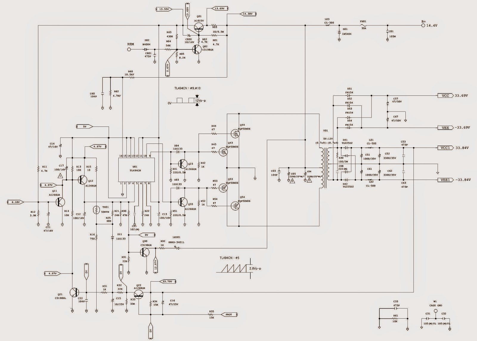

CLICK ON THE PICTURES TO ZOOM IN