Be
sure to pull out the plug from the outlet. Remove the front panel, the
pre-filter, the stamina power carbon and the HEPA filter from the main unit.
Removing the stand
Remove the front panel.
Take out the pre-filter, the stamina power carbon and the HEPA filter, too.
Place the main unit with the front side facing down ward on the level and
stable surface and remove the thumbscrews (2 pcs.) of the bottom surface. Lay a soft cloth, etc. beneath the main unit
so as not to damage it.Remove the front panel.
Take out the pre-filter, the stamina power carbon and the HEPA filter, too.

Removing the frost panel and the frost base
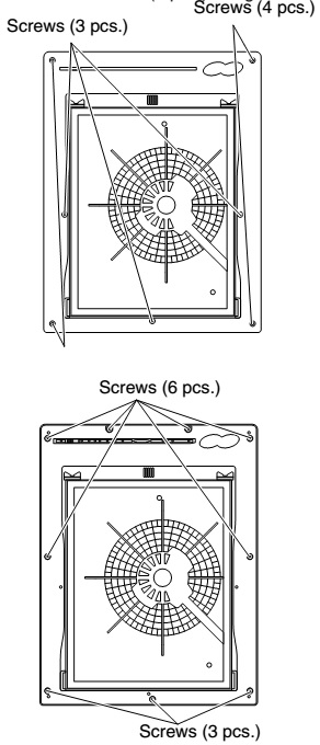
(1) Remove the screws (hexagon head screws (4 pcs.) and tapping screws (3 pcs.)) fixing the frost panel. Use the Allen wrench (3 mm) to remove the hexagon head screws.
(2) Remove the screws (9 pcs.) fixing the frost base.
(1) Remove the screws (hexagon head screws (4 pcs.) and tapping screws (3 pcs.)) fixing the frost panel. Use the Allen wrench (3 mm) to remove the hexagon head screws.
(2) Remove the screws (9 pcs.) fixing the frost base.
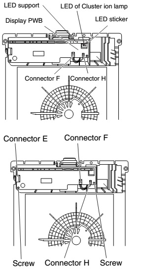
Removing the display PWB, the dust sensor and the
switch PWB
CAUTION:
LED support can not be removed from display PWB (Because there is LED of Cluster ion lamp.)
CAUTION:
LED support can not be removed from display PWB (Because there is LED of Cluster ion lamp.)
(1)Remove
the screws (2 pcs.) fixing th display PWB.
(2) Pull out the connector F and remove the dust sensor.
(2) Pull out the connector F and remove the dust sensor.
Unscrew
the switch PWB support to remove it.
Make
harness processing in assembling as mentioned in the figure. Confirm whether
the movement of the power supply button is smooth after assembling.

Removing the relay PWB & fan
(1) Pull out the connectors H and J. Unscrew the relay PWB to remove it.
(1) Pull out the connectors H and J. Unscrew the relay PWB to remove it.
Removing the fan
(1) Loosen the nut and remove the fan washer, the rubber washer, the fan washer, the fan, the fan washer T2 and the washer.
(2) The tie torque of the nut is 1.5 Nm.
(3) Apply the screw lock (Three Bond 1401B) to the shaft and tighten the nut. To reduce the fan face run-out, never touch the periphery of the fan when tightening the nut.

Removing the motor
(1) Loosen the screws (3 pcs.) fixing the motor angle to remove it.
(2) Pull out the lead wire cover.
(3) Loosen the screw (1 pc.) fixing the electric equipment box cover to remove it.
(4) Pull out the connector C of the power supply PWB and take out the motor.
(1) Loosen the screws (3 pcs.) fixing the motor angle to remove it.
(2) Pull out the lead wire cover.
(3) Loosen the screw (1 pc.) fixing the electric equipment box cover to remove it.
(4) Pull out the connector C of the power supply PWB and take out the motor.
Removing the high-voltage unit ass’y
(1) Remove the screws (2 pcs.) fixing the cluster. (2) Pull out the connectors J and K to remove the high-voltage unit ass’y from the casing.
(1) Remove the screws (2 pcs.) fixing the cluster. (2) Pull out the connectors J and K to remove the high-voltage unit ass’y from the casing.

Cautions
when replacing the high-voltage unit ass’y
Never touch the discharging parts (ceramic panel) with bare hands. No dust or oil of your hands must be adhered to the high-voltage unit ass’y. (They may hamper the emission of the ion.) Always hold the case (resin) with clean gloves during the replacement. If you touch the unit, wipe it off with alcohol. Never forget to unplug the unit before the operation. Confirm fully the connection of the high-voltage harness and the relay harness. Mount the high-voltage unit ass’y on the casing with the cluster holder. Install the high-voltage harness and the relay harness so that they will not come to contact with each other.
Never touch the discharging parts (ceramic panel) with bare hands. No dust or oil of your hands must be adhered to the high-voltage unit ass’y. (They may hamper the emission of the ion.) Always hold the case (resin) with clean gloves during the replacement. If you touch the unit, wipe it off with alcohol. Never forget to unplug the unit before the operation. Confirm fully the connection of the high-voltage harness and the relay harness. Mount the high-voltage unit ass’y on the casing with the cluster holder. Install the high-voltage harness and the relay harness so that they will not come to contact with each other.
Removing the motor thermal fuse
(1) Remove the motor from the casing and then the thermal fuse ass’y from the groove of the casing. The following diagram shows the installation position of the thermal fuse ass’y.
(1) Remove the motor from the casing and then the thermal fuse ass’y from the groove of the casing. The following diagram shows the installation position of the thermal fuse ass’y.
The
attachment position of Fuse is carried out as follows. A temperature fuse ass'y should be located in
the center of rib-B. (The terminal of a temperature fuse ass'y should be
located in an rib-A outdoors side.)

Removing the power supply PWB
Pull out the connector on the power supply PWB to remove the PWB.
Pull out the connector on the power supply PWB to remove the PWB.

CIRCUIT DIAGRAM

CLICK ON THE PICTURES TO MAGNIFY