Amplifier
Output . . . . . . . . . . . . . . . . . . . . . . . . . . . . 250W/5
Frequency Response . . . . . . . 20 Hz to 160 Hz (-24 dB/oct.)
Power Supply
U, C models . . . . . . . . . . . . . . . . . . . . . . . . . AC120V, 60 Hz
A model . . . . . . . . . . . . . . . . . . . . . . . . . . . . AC240V, 50 Hz
B, G models . . . . . . . . . . . . . . . . . . . . . . . . . AC230V, 50 Hz
R, T models . . . . . . . . . . . . AC110/120/220/240V, 50/60 Hz
Power Consumption . . . . . . . . . . . . . . . . . . . . . . . . . . . . . 60W
Dimensions (W x H x D) - 340 x 432 x 370 mm (13-3/8"
x 17" x 14-9/16")
Weight . . . . . . . . . . . . . . . . . . . . . . . . . . . 17 kg (37 lbs. 7
oz)

Disassembly
Removal
of Front Panel Ass'y
Remove 4 screws (1) and then remove the Front Panel Ass'y in Fig. 1.
Use an Allen wrench (3mm) to unscrew the Front Panel Ass'y
Remove 4 screws (1) and then remove the Front Panel Ass'y in Fig. 1.
Use an Allen wrench (3mm) to unscrew the Front Panel Ass'y
Remove
8 screws (2) and then remove the Base Ass'y in Fig. 2.
Remove 4 screws (3) and then remove the Loud Speaker in Fig. 2.
Remove 4 screws (3) and then remove the Loud Speaker in Fig. 2.
Remove
12 screws (4) in Fig. 3.
Arrow marks (<=) are printed to identify the screws to be removed.
Arrow marks (<=) are printed to identify the screws to be removed.
When
assembling the Rear Panel, check to ensure that the gasket is not damaged so as
to prevent air leakage from occurring.

Installation
of emblem
1. Put the emblem into the cabinet at the specified position.
2. Place a piece of cloth/wood on top of the emblem.
3. Using a mallet, hammer the emblem in place through the cloth/wood.
Use special care not to cause damage to the emblem or cabinet while hammering the emblem.
1. Put the emblem into the cabinet at the specified position.
2. Place a piece of cloth/wood on top of the emblem.
3. Using a mallet, hammer the emblem in place through the cloth/wood.
Use special care not to cause damage to the emblem or cabinet while hammering the emblem.
Installation
of power switch
Rapid cures bond (such as 5 minute epoxy) is required to fix the power switch.
Apply rapid cures bond (such as 5 minute epoxy) to the power switch (the area which contacts the rear panel), insert it in the rear panel and make sure it is fixed.
(Inserting the power switch in the rear panel only would not be sufficient for its secure installation.)
Circuit diagram

PWB - Foil side

For the power amplifier which has been repaired, it is absolutely necessary to confirm that a correct waveform is obtained at points indicated by A and B in the schematic diagram according to the following procedure.
Idling Adjustment
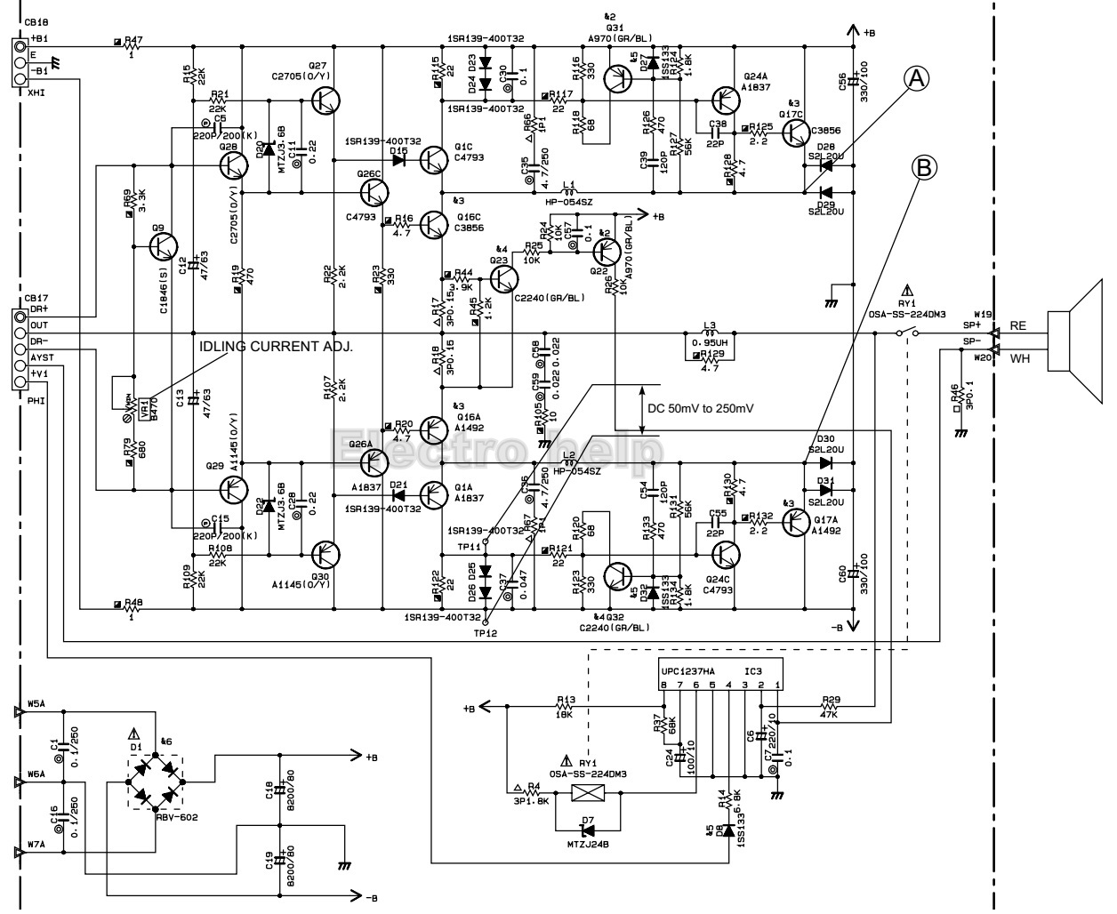
To
stabilize operation of the amplifier, turn ON the power with no input signal
and wait for 1 or 2 minutes in non loaded condition before the adjustment. Adjust VR1 so that the voltage between
terminals TP11 and TP12 is DC 50mV to 250mV.