Service personals should not be exposed to the microwave energy which may radiate from the magnetron or other microwave generating devices if it is improperly used or connected. All input and output microwave connections, waveguides, flanges and gaskets must be secured. Never operate the device without a microwave energy absorbing load attached. Never look into an open waveguide or antenna while the device is energized.

2.CLOCK APPEARS ON DISPLAY


Never
operate the oven until the following points are ensured.
(A) The door is tightly closed.
(B) The door brackets and hinges are not defective.
(C) The door packing is not damaged.
(D) The door is not deformed or warped.
(E) There is not any other visible damage with the oven.
Servicing and repair work must be carried out only by trained service engineers.
All the parts marked "*" on parts list are used at voltages more than 250V.
Removal of the outer wrap gives access to potentials above 250V.
All the parts marked "∆" on parts list may cause undue microwave exposure, by themselves, or when they are damaged, loosened or removed.
THE
WIRES IN THIS MAINS LEAD ARE COLORED IN ACCORDANCE WITH THE FOLLOWING CODE
GREEN-AND-YELLOW
: EARTH
BLUE : NEUTRAL
BROWN : LIVE
BROWN : LIVE
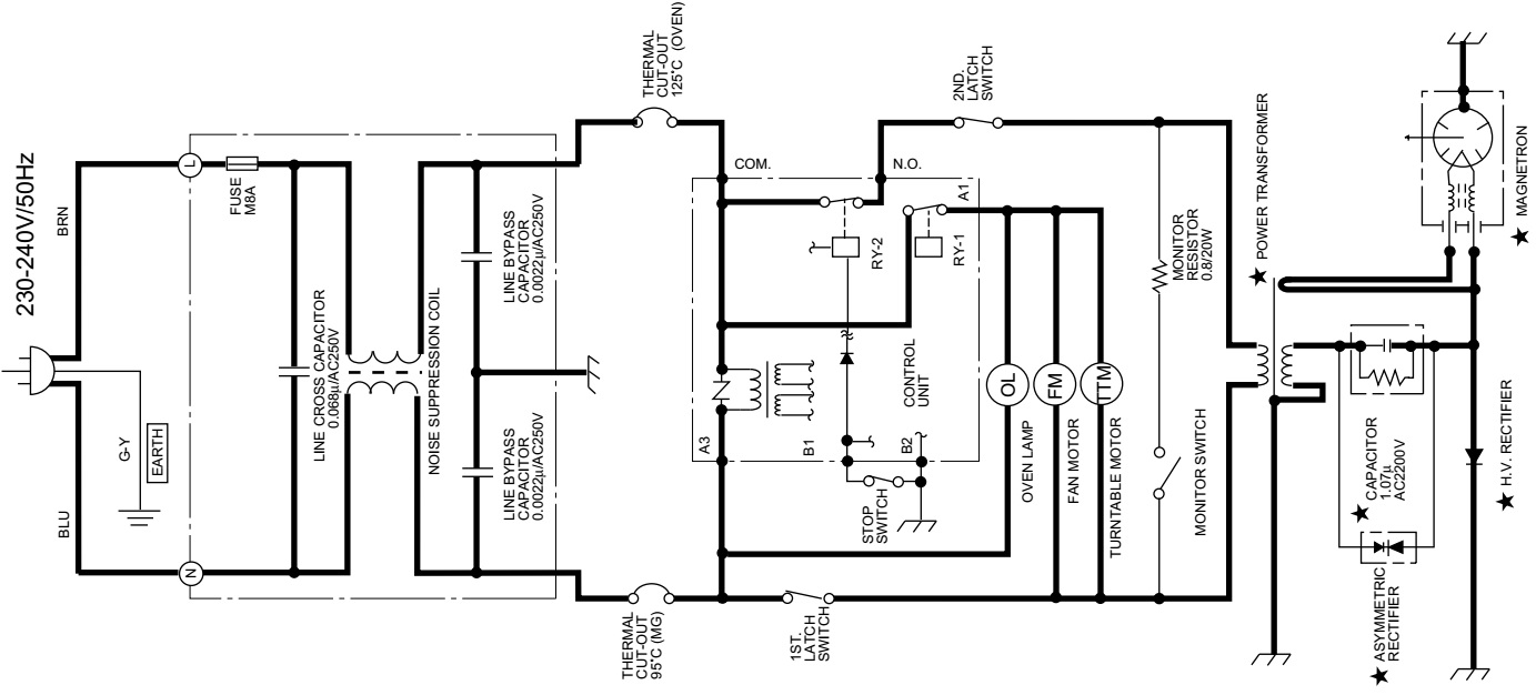
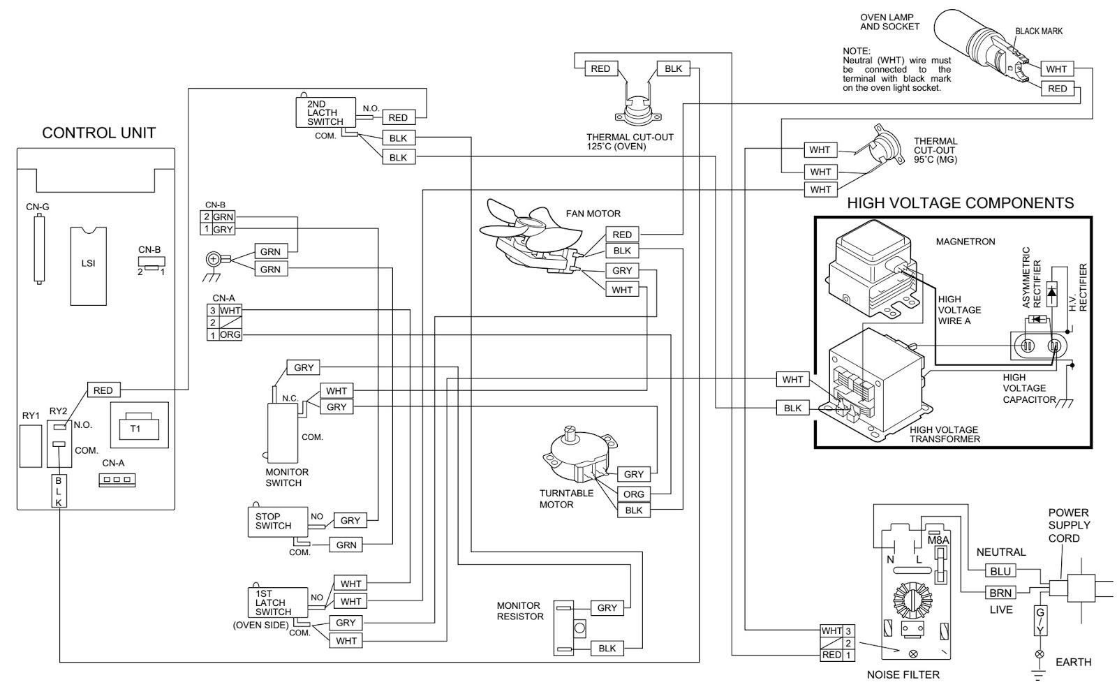
Circuit diagram [Click on the pictures to zoom in]
1.DOOR CLOSED2.CLOCK APPEARS ON DISPLAY

1. DOOR
CLOSED
2. COOKING TIME PROGRAMMED
3. START KEY TOUCHED
2. COOKING TIME PROGRAMMED
3. START KEY TOUCHED
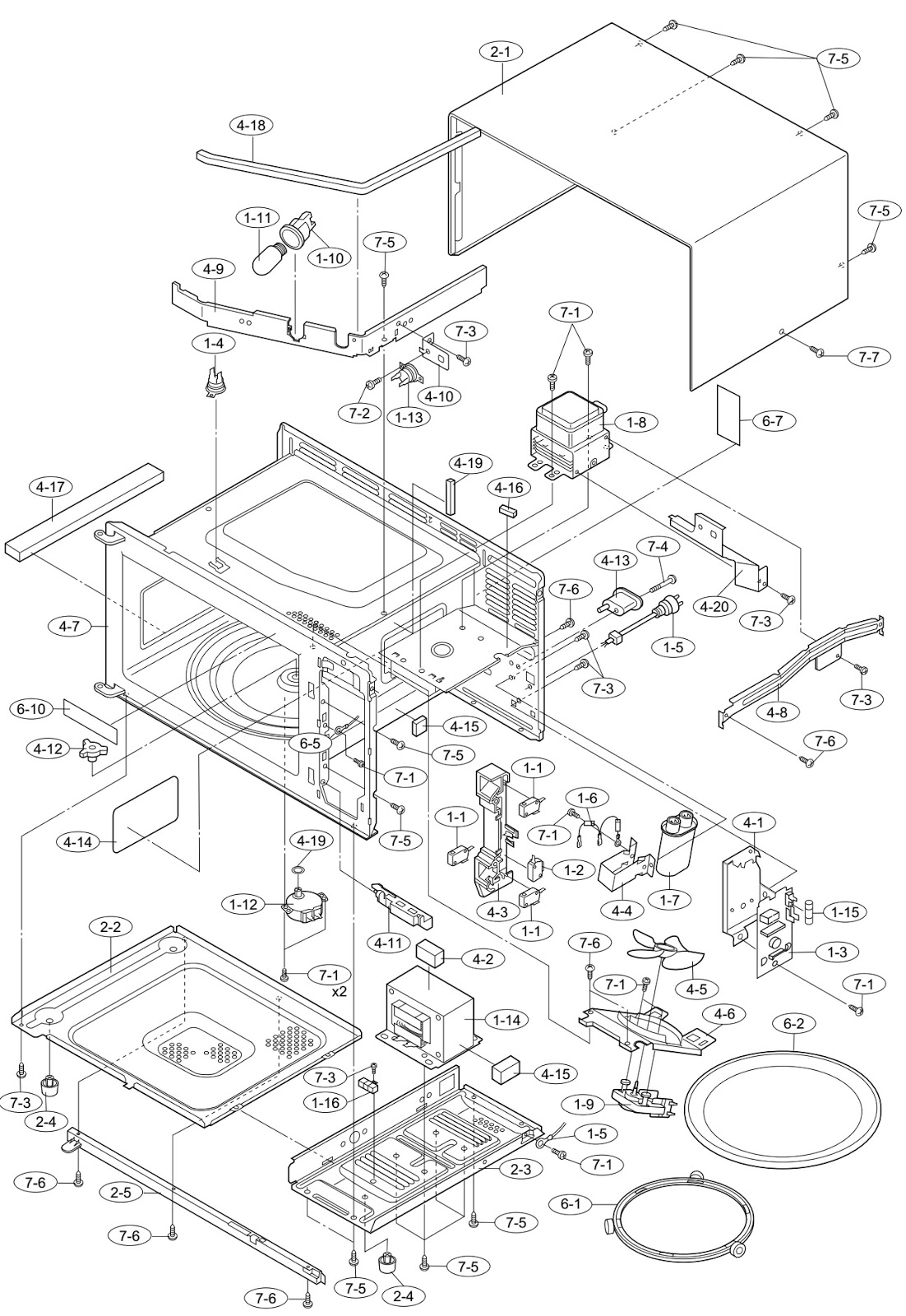
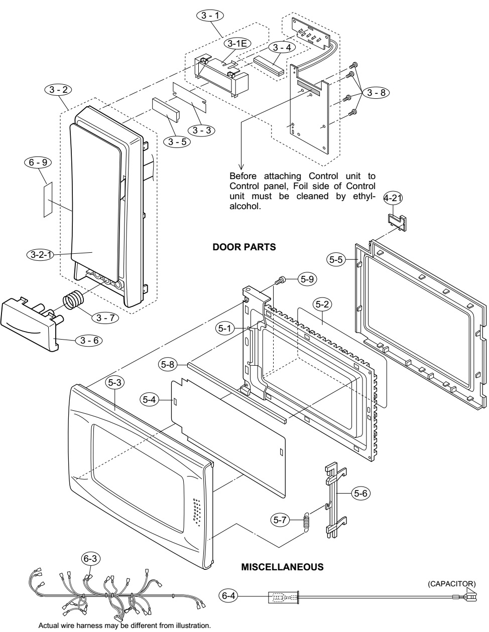
Exploded views
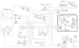
Wiring diagram
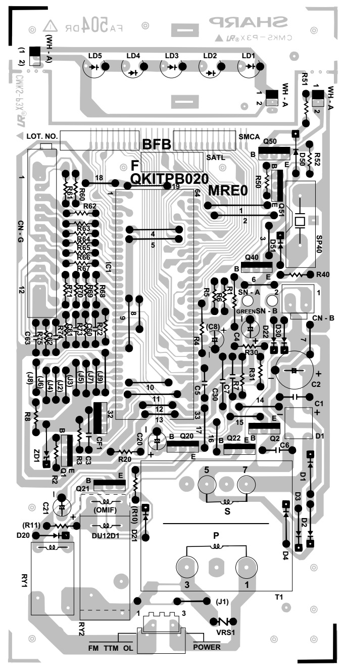
Circuit diagram and PWB

OFF CONDITION
Closing the door activates all door interlock switches (1st. latch switch, 2nd. latch switch and stop switch).
IMPORTANT
When the oven door is closed, the monitor switch contacts (COM-NC) must be open.
When the microwave oven is plugged in a wall outlet, rated voltage is supplied to the point A3+A5 in the control unit.
1. The display shows SHARP , MICRO- , WAVE and OVEN .
2. To set any programmes or set the clock, you must first touch the STOP/CLEAR pad.
3. [ : ]appears in the display.
NOTE: When the oven door is opened, the oven lamp comes on at this time.
1. Rated
voltage is supplied to the primary winding of the power transformer. The
voltage is converted to about 3.3 volts A.C. output on the filament winding and
high voltage of approximately 2000 volts A.C. on the secondary winding.
2. The filament winding voltage (3.3 volts) heats the magnetron filament and the high voltage (2000 volts) is sent to the voltage doubling circuit, where it is doubled to negative voltage of approximately 4000 volts D.C.
3. The 2450 MHz microwave energy produced in the magnetron generates a wave length of 12.24 cm. This energy is channeled through the waveguide (transport channel) into the oven cavity, where the food is placed to be cooked.
4. When the cooking time is up, a signal tone is heard and the relays RY1+RY2 go back to their home position. The circuits to the oven lamp, power transformer, fan motor and turntable motor are cut off.
5. When the door is opened during a cook cycle, the switches come to the following condition.
