1CHANNEL POWER AMPLIFIER –
schematic – exploded view – troubleshooting - JBL GTO7001 Car Audio


Specs:
• 425W RMS x 1 channel @ 4 ohms and ≤1% THD + N*
• 700W RMS x 1 channel @ 2 ohms and ≤1% THD + N*
• THD + N: 0.02% (rated power @ 4 ohms)
• Signal-to-noise ratio: 80dBA (reference 1W into 4 ohms)*
• Signal-to-noise ratio: 107dBA (reference rated power into 4 ohms)
• Frequency response: 20Hz – 330Hz (–3dB)
• Max power: 700 watts
* CEA-2006A-compliant.
• THD + N: 0.02% (rated power @ 4 ohms)
• Signal-to-noise ratio: 80dBA (reference 1W into 4 ohms)*
• Signal-to-noise ratio: 107dBA (reference rated power into 4 ohms)
• Frequency response: 20Hz – 330Hz (–3dB)
• Max power: 700 watts
* CEA-2006A-compliant.
Power Input Connectors
• +12V: Connect to the positive terminal of the vehicle’s battery. 4 AWG wire is recommended. Install an appropriate fuse holder and fuse (75A minimum) within 18 inches of the battery. Make sure the wire is not damaged or pinched during installation. Install protective grommets when routing wires through the firewall or other sheet metal.
• GND: Connect to the vehicle’s chassis.
Speaker Output Connectors
• Connect the subwoofer to terminals, observing proper polarity. Either + or – terminal may be used. Minimum total impedance is 2 ohms.
• Connect the subwoofer to terminals, observing proper polarity. Either + or – terminal may be used. Minimum total impedance is 2 ohms.
DBO (Dynamic Bass Optimization)
Variable Subsonic High-Pass Filter With Variable Boost (Q)
• For woofers in tuned (vented) enclosures, set the Frequency control to a value 10Hz below the enclosure’s resonance (tuned) frequency.
• For woofers in sealed boxes, set the control to any value you prefer between 30Hz and 50Hz.
• Set the Boost control according to your preference, being careful not to apply enough boost to damage your woofer(s). A DBO High-Pass Filter Frequency control, variable between 10Hz and 100Hz. B DBO Boost control provides up to 12dB of boost slightly above the high pass filter’s frequency.
Setting Input Level
A Turn Input Level control counterclockwise to 6V (minimim).
B With a dynamic music track playing, turn the head unit’s volume control to the 3/4 position.
C Turn Input Level control clockwise until the bass output is proportionate to the output of the high-frequency speakers, according to your preference.
D Input level is now adjusted correctly.
EXPLODED VIEW & PARTS LIST

SCHEMATIC


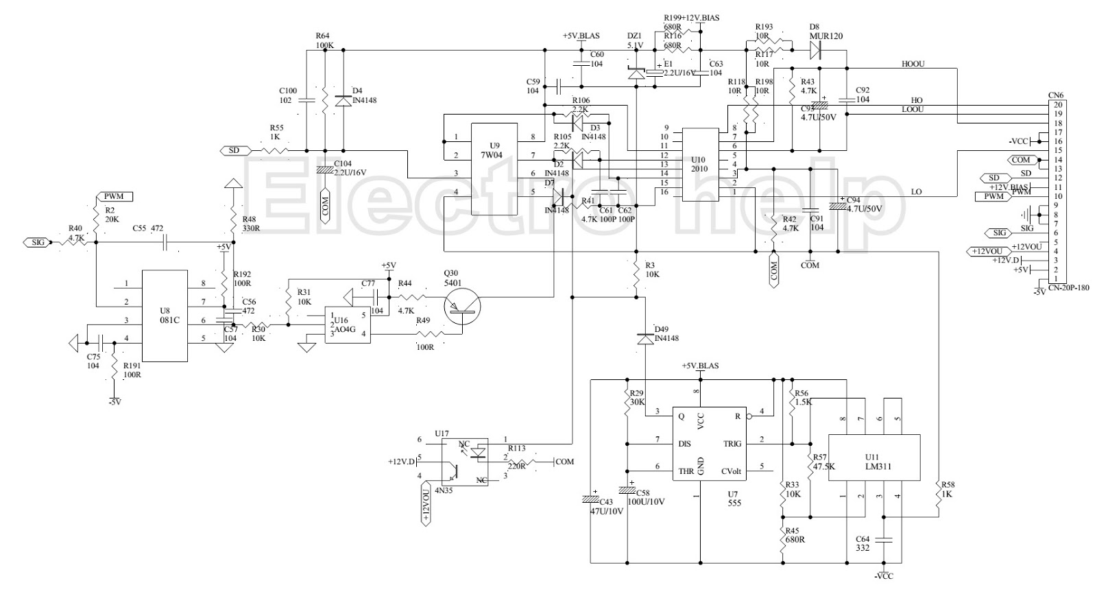


Click on the pictures to Zoom In
Troubleshooting
Status LED on Amplifier not Lit - Head
Unit (Source) Turned ON Verify:
A. Remote turn-on wire from source to amplifier has proper voltage
B. Power (B+) connections at amplifier, terminal blocks, and battery are secure
C. Ground (GND) connections at amplifier and vehicle chassis are secure
D. Battery B+ fuse (if used) is OK
E. Amplifier fuse is OK
F. B+ at battery and B+ at amplifier has proper voltage
Status LED’s Lit, No Output from
Speakers in Normal Operating Condition Verify:
A. RCA cables from amplifier to source are securely connected
B. Volume adjustment on amplifier is correctly adjusted
C. Source is ON and playing
A. RCA cables from amplifier to source are securely connected
B. Volume adjustment on amplifier is correctly adjusted
C. Source is ON and playing
Engine Noise From Speaker(s)
Turn source OFF, Disconnect RCA cables at amplifier. If noise stops, check equipment & cables leading to amplifier. Verify:
A. RCA cables are of good quality with no breakage to internal shields
B. RCA cables from source to amplifier are not run alongside any power cables.
Turn source OFF, Disconnect RCA cables at amplifier. If noise stops, check equipment & cables leading to amplifier. Verify:
A. RCA cables are of good quality with no breakage to internal shields
B. RCA cables from source to amplifier are not run alongside any power cables.
Amplifier Output Distorted Music Verify:
A. Source output music to amplifier is not distorted
B. Source output sensitivity is correctly adjusted.
A. Source output music to amplifier is not distorted
B. Source output sensitivity is correctly adjusted.
Amplifier Shuts Down, Green LED’s are
Lit - Amplifier is in Thermal Protection Mode Verify:
A. Amplifier is mounted with adequate air circulation around heat sinks or vents
B. Amplifier is not mounted under carpet or sealed enclosure
C. Speakers meet correct impedance for application (mono or stereo hookup).
A. Amplifier is mounted with adequate air circulation around heat sinks or vents
B. Amplifier is not mounted under carpet or sealed enclosure
C. Speakers meet correct impedance for application (mono or stereo hookup).
Amplifier Does Not Turn ON, and Red LED
is Lit Amplifier (and not Connected to a Shorted Speaker) Verify:
A. Speaker crossover (if used) is not defective.
A. Speaker crossover (if used) is not defective.