Saturday, October 27, 2018

LS55A31 – Haier LCD TV – repair help – Power board circuit diagram and descriptions, firmware update


Model: LS55A31 (DH1TV0A0801), 0907732277 RTD2995 square board (no template interface), Power: 0094065514A
TD2995D is an LCD TV solution with support for domestic specifications. It is applied to 26 inches or more (including 26 inches).
The product. Equipped with a liquid crystal display with interface type Vby1. The resolution of the supported screen can reach upto 4K*2K.
The movement module uses REALTEK's video and audio decoding chip RTD2995D  uses NXP's silicon tuner core.
The TDA18275, the system performance is stable, the picture quality is fine.
The video part of the movement module supports 1 channel AV signal input (multiplexed with YPbPr Y signal), 1 channel Video signal output, 1 way YPbPr video signal, 2 way HDMI, 1 way network port, 1 way USB2.0, 1 way USB3.0, all the way TF card, built-in WIFI.
Uses TI's 54628 to power the CPU, the core voltage output is 1.2V, the current is about 4.8A, close to 5A, so choose 6A DC/DC.
+12V Normal to +5V Standby and +5V Normal
This circuit consists of a PWM switching power supply consisting of U17-TI54328 peripheral components. U17 is the switching control device and L7 is the storage inductor. Output 5V  is fed to the control circuit inside the U17(2) pin via R84, R79 partial pressure feedback for PWM control to ensure 5V voltage regulation.
When the switch  is closed, the current of the 5V power supply flows through the self-inductance of L7, and the current gradually rises and is stored as magnetic energy. Self-induced potential.
The direction is left positive and right negative flow through L7, the current charges the capacitor, the voltage across the capacitor gradually rises, and supplies power to the load, when the voltage across the capacitor exceeds
 5V, it will send the feedback voltage of FB terminal of (2) pin of U17 to make the internal switch of TI54328 cut off. At this time, the self-inductance potential of L7 is left and right.
The self-inductance potential of the direction supplies power to the load. When the feedback voltage of the U17(2) pin is lower than 5V, the internal switch is turned on and the regulated voltage is 5V.
Note: U17(1)EN pin control voltage 3.75V, (3) external compensation component, establish voltage control error amplification circuit through external RC component output, realize OSC oscillation frequency control, oscillation frequency 340KHz, output current 3A.
VBY1 power supply part.
In the circuit, Q15 is the control, U16 the electronic switch. When the power is turned on, the main chip U8 (N5) pin outputs PANEL_ON high level voltage to make Q15.
Saturated on, 12V voltage is divided by R209, R204, U16 turns on 12V voltage through U16 source and drain, and is sent to the screen via VBY1 socket
The control panel acts as the operating voltage for the control board.
Control section
On/standby control circuit
When the TV is in the standby state, the PWR_ON/OFF control voltage output from the U8 (N6) pin is high, and the control power board 12V is not lost.
When the TV is normally turned on, the PWR_ON/OFF control voltage output from the U8 (N6) pin is low, and the 5V standby voltage is controlled by R19.
The source board 12V has an output.
Backlight start control
When turned on, the U8 (R6) pin BL_EN outputs a low level to turn off the Q13 transistor, and the 5V_USB voltage is sent through the R18, R56 3.3V voltage.
The backlight driving circuit starts the backlight driving circuit and turns on the backlight. If the voltage is zero, it indicates that the backlight cannot be lit. The reason should be in the movement.
Backlight brightness control
When turned on, U8 (R5) pin BL_ADJ output PWM is amplified by Q10 transistor, D5V voltage is sent through R111, R113 3.3V voltage
The backlight driving circuit starts the backlight driving circuit to provide a driving pulse signal for the backlight, so that the Q10 and related circuits are faulty the backlight driving circuit stops working, and there is no grating, no image, and there is a sound fault. (NC means there is no such component).
Remote control circuit
When the remote control receiver output control signal is sent to U8 RTD2995D (T5) pin, the CPU receives the command signal and starts to work. U8 output is high.
The low level causes the indicator to flash, and the red indicator on the remote control head should be constantly lit when the TV is in standby.
The infrared receiving head may also be damaged. Use the oscilloscope to detect at R28 and press the remote control. If there is a waveform display, the remote receiving head is normal.
The waveform indicates that the remote control receiving head is damaged, and the normal remote receiving head is replaced for reconfirmation.
 DDR circuit
DDR is a frequently problematic component. For DDR, when the program is running, “BIST” will appear. “BIST” is the meaning of Build In SelfTest. Thinking is the automatic detection of the DDR module by the chip power-on. The BIST is completed and will automatically find the best phase value.
BIST: OK - indicates that the primary test passed.
BIST: Fail - indicates that the primary test failed. There is a problem, most of the power supply's 12V power-on time is relatively long, resulting in the DDR part during initialization.
It has not been started yet. It is a hardware problem with abnormal VCC power supply. Performance is not booting.
Maintenance Tip: Regarding the failure of the amplifier, it shows that there is no sound from the speaker. First of all, make sure that the amplifier itself has no bad solder joints and have continuous soldering. Secondly Analyze whether it is other hardware reasons, including the 12V power supply of the power amplifier, whether there is output on the left and right, and finally see if MCLK, SCLK, etc. are positive.
Common fault repair and maintenance method.
For the movement board, first of all, visually check whether the material is inserted correctly, whether there is a bad solder joint or a joint weld. After eliminating these human factors, then Confirm the board hardware or software issues.
For hardware, first the power supply should work properly. 5V Normal and 5VStb ripple are less than 100mV,
The VDDC, 1.5V, 3.3V, 2.5V ripple is less than 50mV.
No power failure troubleshooting ideas.
1, first determine whether the fault is on the motherboard or on the power board.
The 5V-STB output from the (7) pin of the movement board CN8 is the standby voltage. If there is no voltage on this pin, the fault is on the power board. (10) The foot is the movement
The board is sent to the power supply's open standby voltage. If it is turned on twice, the measured (10) pin voltage can be changed from low level to high level. If CN8 (7) pin is lost, the 5V-STB is the standby voltage. It should be determined that the power-ON fault is not on the components on the power board. If the measured (10) pin voltage cannot be changed from low level to high level.
If the level is above 2.5V, the fault will not be turned on the movement board.
2. Check the devices on the motherboard
First, check whether the appearance color of the IC on the motherboard is abnormal, whether there is crack on the surface, and secondly, check whether the magnetic capacitor and the electrolytic capacitor foot are off, and the surface.
Whether it is bulging or cracking. The third is to check the AV; HDMI; VGA and other port anti-static components are not cracked, etc., the fourth is to measure the main chip pin-to-ground resistance, in order to judge whether the TC is broken down,
3. Force the power board assembly to check the power supply.
In order to confirm the fault location, the power module can be forced to open, the RTD2995D movement board is characterized by the movement component control unit assembly output only 12V
The output voltage is sent to each DC/DC block on the main board and the three-terminal voltage regulator. When working, the VDDC of the core board, NOYMAI voltage and FLASH, DDR are measured.
4. Check the clock oscillation circuit and reset circuit of the main chip. The reset circuit is a necessary condition for ensuring the normal operation of the main chip. When checking the reset circuit,  measure the reset pin voltage at the instant of power-ON, can from the high level to the low level, when checking the clock oscillation circuit, it is mainly to measure the voltage or waveform at both ends of the crystal oscillator, or  replace the crystal.
5 Check whether the transmission channel is smooth between different integrated blocks.
The transmission channel between the integrated blocks of the LCD TV must be unblocked, especially the information transmission channel between the FLASH block and the user memory.
FLASH block, 5 SPT digital signal waveforms or voltages are hopping to confirm whether the control system operating conditions are true, and the total tuning is turned off.
The line is connected across the resistor to verify that the load on the I2C bus is faulty. The bus voltage is usually around 3.3V.
6 Refresh the FLASH block program
Program changes in the FLASH block will also cause no power-on failure. For the FLASH block program, the near-line refresh can eliminate the data change.
Most of the flat-panel TVs have USB ports, are basically open, and use USB ports for software upgrades. Of course, a TV that have not a normal standby process cannot be software refreshed through the USB port. It can only use the programmer to write programs to the FLASH block.
7 Replace the chip or motherboard
If the fault cannot be eliminated by the above method, the fault can only be corrected by changing the main chip FLASH memory and the user memory or the main core board.
Maintenance case
1) fault: No boot, the indicator light is on.
Analysis and maintenance: The test start-up voltage is 4.5V, but the screen power supply 12V voltage is 0. Firstly, the voltage of each part of the core board is measured, and the bus voltage is normal.
In the principle of soft first and then hard, software upgrade or FLASH memory block, after the fault is finally replaced, the TV works normally.
2) fault: Automatic shutdown, crash, standby does not boot.
Analysis and overhaul: 12V, 5V, 3.3V, normal power supply, main chip U9, U205, U2 power supply normal measurement U103 (1) foot voltage 3.3V, positive often 1.5-2.5 jitter, may be the flash chip write protection state, replace the FLASH memory block (note, replace the core that must carry data Tablet) After the replacement, there is an image, screen, which needs to be upgraded.
3) fault: The screen is reddish when connecting VGA.
Analysis and repair: When the VGA appears, the picture is reddish. Go to the website to download the software upgrade.
Power primary

5VSB, 12V rectified output, feedback sampling circuit, voltage regulator circuit, power supply ON/OFF circuit, LED driver circuit, LED chip power supply, LED overvoltage protection circuit
Power board maintenance method and maintenance flow chart.
Protection function introduction (OVP overvoltage protection, OCP overcurrent protection, OPP overpower protection, LUVP undervoltage protection)
AC input overvoltage protection OVP
The varistor VR1 in this protection circuit, when the input voltage is higher than its specification voltage value.
When VR1 is short-circuited, the current between LN increases rapidly, causing F1 to open.
AC input under voltage protection LUVP.
AC power failure detection consisting of R128, R129, R130, C101, R124, U100 and Overvoltage monitoring circuit, When the PIN 3 voltage of the U100 reaches 1.05V, the PIN3 protection function is turned on. When the PIN3 voltage is lower than 0.8V and higher than 6.0V, the LD7537 chip Turn off the PWM output so that 5VSB and VCC have no output for protection purposes.
OCP&OPP
12V/5Vsb OCP (over current protection) Pin by sampling resistor R115 and R120, C102 and U100 4 constitutes an output overcurrent protection circuit. When the output current is too large, causing The current flowing through R115 is large, causing a large voltage difference of R115, and the PIN4 voltage of U100 ≥0.85V, U100 Off, thus achieving protection purposes.
5Vsb, 12V OVP
The feedback sampling circuit and the U100 VCC power supply circuit form a 5Vsb, 12V output overvoltage protection circuit. When the 5Vsb output reaches 7V or higher, or
When the 12V output reaches 14.5V or higher, the output voltage is fed back to U100 through the feedback sampling circuit, and the VCC power supply circuit supplies U100 PIN5 voltage to increase.
When U100 PIN5 voltage is higher than 26V, U100 off, so that 5Vsb, 12V no output, for protection purposes.
VLED OVP
Composition of Q6F, R31F, R32F, R30F, R29F, R28F, R53F, R26F, R25F, R52F, R33F, R34F, C14F, R36F, U2F, R35F, C6F 12V, 5Vsb output overvoltage protection circuit. When the VLED output reaches 200V or above, the Q6F base voltage is raised. When the Q6F base current is reached, the voltage is reached.
When the value is constant, the Q6F is turned on, the voltage difference of R31F is increased, the voltage of PIN7 VS pin of U1F is increased, and when the voltage of PIN7 is greater than 1.25V, the protection is performed.
The road starts to move, U1F OFF, so U1F does not work, VLED has no output, and achieves the purpose of protection.
Software upgrade method (provided by model manager)
Normal upgrade method
1. Copy the software to the root directory of the U disk and change the file name to: install.img
2. Insert the USB flash drive into the TV USB port, press the menu button on the remote control, and then press 8893 to enter the Haier factory menu home page, move the cursor Go to the Rtd2995 upgrade and press the OK button.
After pressing the OK button, there will be a prompt, select the confirmation button, the software will be automatically upgraded, and the machine will start automatically after the upgrade is completed.
Abnormal upgrade method
1. Copy the software to the root directory of the U disk, change the file name to: install.img, and insert the USB disk into the TV USB interface.
2. Press and hold the menu button on the control panel, then press the TV's AC switch to set the TV to off, and then enter the upgrade interface after the TV enters the upgrade interface.
The menu button on the board is released.

Tuesday, October 23, 2018

Fagor, Brandt - Induction hobs - working – error codes – troubleshooting - electrical connection


There are two techniques of glass-ceramic heating:
* The infrared.
* The induction.
These glass-ceramic hobs are as like as two peas.
The difference is only obvious once hobs are turned on.
The infrared one glows red while the induction doesn’t seem to operate.
The first is provided with radiant or halogen sources that transmit heat by radiation and conduction.
The second feeds a magnetic source, an inductor, which is placed under the glass-ceramic surface and transforms the magnetic energy into heat.
The traditional electrical hotplate is based on thermal conduction, while induction is based on the principle of the electromagnetic field.
The principle of heating by induction is a natural phenomenon discovered in the 19th century by several physicists, among whom Léon Foucault. He highlighted the development of currents facing the magnetic field in a moving metallic mass or a fixed metallic mass run through by a variable magnetic flux. These eddy currents in comparison to short-circuits cause a heating effect (Joule effect) in the mass.
Only since the middle of the 20th century induction started being used as a heating means, mainly in industries like the steel (induction furnaces). Induction only found its place in kitchens in the 80s, or even 90s for domestic electrical appliances with the marketing of the hob named IX1. The IX2 generation followed in 1992, IX3 (1996), IX3WR (2000) and currently IX4000 (2002) and IX6 (2005) generations.
The operating principle is innovating. Contrary to other cooking modes, it is the container itself, which heats and not the hob.
You put a saucepan down and this is sufficient to initiate the heat while the hob remains cold. The heating element is nothing but the container metal, which transforms the magnetic energy into thermal energy.  Induction qualities are flexibility, low inertia, easy cleaning, good efficiency and thermal safety.  Induction enables a litre of water to boil in two minutes, milk to heat without overflowing and chocolate to melt just as desired. Induction efficiency may reach up to 90% according to the types of cooking.
With such a technique, only the container heats. Inertia is therefore low and, above all, the plate temperature never exceeds the saucepan temperature.  Stepping from the mildest temperature to the strongest power, in an instant and while diffusing heat in a homogeneous way.
This technology is incomparable to those of present due to the induction method.
Operating principle
An induction hob operates due to the electromagnetic properties of most containers used on traditional hobs.  One can compare this hob with a transformer of which the secondary winding would have been shorted. A significant internal current arises therein and causes quick heating.
The saucepan can be compared with a shorted set of concentric whose internal resistance is not zero.  From the function keys, you control the electrical power supply to the transformer primary winding which generates a magnetic field. This field induces currents at the bottom of the container placed on the hob. These induced currents heat the container immediately, which transmits the produced heat to the food inside. Cooking is performed efficiently with almost no loss of energy. The appliance heating power is pushed to its maximum.
Skin effect
An induced current in a metallic mass will only cause significant heating if it flows through a significant resistor (P=RI2). A ferrite saucepan has only low resistivity. This is where a second natural phenomenon occurs, which is called ‘Skin effect’.
The propagation of the high-frequency current is not performed in the same way as a direct current.  Contrary to direct current, where current flows with consistency in a conductor, in HF its density varies and decreases exponentially as you move away from the conductor surface.
The current flows predominantly in wire periphery. The decrease in the effective cross-sectional area of the conductor causes an increase in its resistance.
At a 20KHz frequency, and for a steel saucepan (magnetic ferritic material), the thickness of the saucepan in which the induced currents flow is approximately 35 µm. This allows generating a current in only a part of the saucepan bottom. The resistance becomes significant and the heating consequent therein.
For a non-ferritic material, such as aluminium, the thickness is approximately 590 µm, the saucepan behaves then as a quasi-zero resistor (short-circuit), which is prejudicial to electronics. The board will take this discrepancy into account and will display the phenomenon by making the control panel flash. Therefore, this type of material is not adapted.
The efficiency is the ratio that exists between consumed energy (gas or electricity) and energy converted into heat. Large differences exist between induction, range-top appliance, and other cooking modes. These efficiencies may vary depending on the diameter and quality of the container used.
Removing the container from a source is sufficient to stop the cooking immediately, there is no energy waste. As long as there is no container on a source, the source does not heat, the power indicator lights are flashing. This hob consumes thus much less energy than hobs fitted with traditional gas or electricity hobs.
Electrical connection
Hobs with three or more sources have five wires to be connected. Wires other than the yellow/green shall be connected in pairs to a 32 Amp connector (connector specific for cooking).
Hobs loosely fitted, with connecting block or combined with gas can be connected to a 16 A connector (Conventional connector).
If the user has three-phase power supply, the connection can be distributed over two phases by separating the black wires of the 5-way cord.  The advantage is to work only with a 16A protection.
On hob power-up or after prolonged power cut, a luminous code is displayed on the keyboard. It disappears automatically after 30 seconds, or from the first action on any one key on the keyboard.
Temperature limiter
Each inducer uses a NTC sensor measuring the container temperature through the glass. This system help protecting the hob and the containers against over heating (Pan without food for example).  In case of overheating, the temperature of the pan is regulated around 300°C. This temperature does not allows the deterioration of the PFTE (anti sticking material used in the pans).Damages start above 340/350°C.
Glass ceramic is a silicium-based material that does not expand like glass. Its dimensions do not practically vary up to 750°C, as a part of the molecules composing it expands under heat, while an equal number retracts. A feature of this material is that it is a poor heat conductor and therefore limits heat loss.
The plane surface of the glass ceramic and the sensitive controls make cleaning easy. The own cleaning difficulties of radiant and halogen sources are usually groundless on induction hob, owing to the low temperatures attained by the table. However, a saucepan with humid bottom put on the source leaves limestone traces. Sugar discharges should be cleaned immediately, as in contact with hot glass ceramic the sugar caramelizes. When cooling down, it retracts and attacks the coating. Lastly, the glass-ceramic hob is not a working plane and thus is easily scratched.
Power supply
To supply the inducers, it is necessary to apply a high frequency. To change over from 50Hz to 50KHz it is first necessary to rectify the main voltage through a diode bridge. A filtering capacitor (of 5µF generally) is associated in order to attenuate the high-frequency signals. As shown by the illustration, the rectifier output voltage is approximately the main peak voltage (i.e. 310 VDC approx.) when no inducers are supplied. This voltage drops during the operation.
The inverter is used to transform a DC signal into an AC signal with adjustable frequency. The inverter consists of two transistors (whose technology can vary according to the hob generation), two capacitors and two recovery diodes (indispensable on any inductive circuit).  Transistors are frequency controlled by a generator. This frequency varies between 25KHz (for 2800W) and (50KHz for 500W).
Control
The entire operation is managed by a microprocessor.
* On generation IX1, a specific board performed the control; the power was managed by another board.
* On generation IX2, these two boards have been soldered and have become indissociable.
* On generations IX3, IX3WR and IX4000, power and control are entirely associated. So, the board integrates: A 5 and 12 VDC clipping power supply (which is also the keyboard power supply),  the control part (in liaison with the control keyboard), the rectifier part, the inverter part, and lastly, for board IX4000 and IX6, the filtering part.
The error codes
'Error' codes are a precious aid to diagnostic. Take care to well identify the model to be troubleshooted, as codes do not always have the same meaning.
The test keyboards
During a diagnostic, it is necessary to know whether it is the control keyboard or the power board, which is defective.  However, you must not omit the filter board, which includes two fuse pads and the power supply relay. Generations IX3 on the one hand and IX3WR, IX4000, IX6 on the other hand do not use the same encoding process. It is therefore advisable to be provided with two different test keyboards.
* IX3 keyboard: 79X5460
* IX3WR, IX4000 and IX6 keyboards: 79X9920
This keyboard will enable all the keyboard of each range to be replaced.  In event of degradation with use, base plates can be replaced:
* 6-point base plate (IX3) : 79X5461
* 8-point base plate (IX3WR, IX4000, IX6) : 79x9921
In event of problem with power supply, it is advised to check:
* Whether 'fuse' pads are out of order
* Whether the power relay is controlled (12VDC)
* Whether the relay delivers 230VAC to the board.
* Whether the relay delivers 230VAC to the fan.
Measurements on IX3 power board
These test points are used to check whether the independent filter board
* delivers a voltage for the control supply
* delivers a voltage for the power supply
* power relay is controlled by the command.
Measurements and checks on IX3 WR power board
These test points are used to check whether the independent filter board
* delivers a voltage for the control supply
* delivers a voltage for the power supply
* power relay is controlled by the command.

Thursday, October 04, 2018

Sharp Air Purifier FU 40SE-J Troubleshooting, schematic, working principle, test mode

Air purifier - Sharp FU40SE - fault finding circuit diagram, working principle and more

How the air purifier works
The air purifier uses the internal fan to intake the air in the room through the intake port and discharges the air through the exhaust port after cleaning the air is passed through the internal filters active carbon filter and dust collection filter (HEPA filter). The unit then repeats this process. Odor ingredients are removed by repeatedly passing them through the deodorization filter for gradual adsorption. (At this time, the dust collection filter also adsorbs odor ingredients.)
Some of the odor ingredients absorbed by the filters become separated and are discharged through the exhaust port as odor. Depending on the usage environment, this odor may become strong in several months and the exhaust port may smell. In this case, replace the filters.
While this product is plugged in, it consumes the stand-by power of approximately 0.8W to activate the electric circuit.
Based on the standard of The Japan Electrical Manufacturers Association, JEM1467 The size of the room to be referred to is the one in which dust concentration of 1.25mg/m3 may be reduced to 0.15mg/m 3 within 30 minutes under the condition that the natural ventilation is performed once per hour.
Based on the standard of The Japan Electrical Manufacturers Association, JEM1467 Ten cigarettes are smoked per day in the place where the air cleaner is installed.
Circuit description
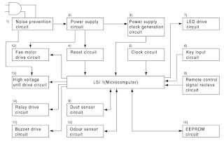
1) Noise-prevention circuit
This circuit protects the circuit from the external noise and lightning surge coming in from the AC plug, and also absorbs the noise outgoing from the AC plug. It consists of the film capacitor C1 and C4, varistor VRS1, current
fuse FUSE1, and line filter L1.
2) Power supply circuit
a) Vm: The commercial power supply (AC220-240V) is put through the current fuse FUSE1 and the thermal fuse, rectified by the diode bridge DB1, and smoothed by the electrolytic capacitor C2.  Then it is supplied as the power input for the fan motor and the hybrid IC (HIC1).
(Vm = approx. DC310 - 340V)
b) VL: The hybrid IC (HIC1) is activated by the DC input Vm and the external coil L2, and has two output terminals.
The first output is changed into VL after being smoothed by the electrolytic capacitor C12.
It is used as the power supply for the buzzer drive circuit, fan motor drive circuit, relay RY1, and high voltage unit drive SSR1 (VL = approx. DC15V).
c) VDD: The second output is smoothed by the electrolytic capacitor C11 before used as the power supply for the microcomputer LSI-1, high-voltage unit drive circuit, relay drive circuit, dust/odor sensor circuits, and LED drive circuit (VDD = approx. DC5V).
3) Power supply clock generation circuit
The voltage between the input terminal to DB1 and its output terminal (GND) is divided by the resistor R21, R22 and R23, and input into the digital transistor Q21.  Then it is converted into the DC square wave signal that has the same frequency with the AC power supply, and input into the pin 31 on the microcomputer LSI1 via the resistor R25 and the ceramosonic capacitor C22.
The microcomputer LSI-1 considers it as the source signal for time count, and decides the power supply frequency and controls the output time.
When this signal retains " H " or " L " state for over certain period of time, the microcomputer LSI-1 assumes it to be a power failure and stops outputs from the fan motor, high-voltage unit, dust/odor sensors, buzzer, and LED.
4) Reset circuit
If the VDD is lower than specified, " L " is input into the pin 18 of the microcomputer LSI1 to reset LSI-1 using the circuit consisting of the reset IC (IC2), R31 and C32.
When VDD is higher than specified, " H " is input into the same pin, reset command is canceled, and LSI-1 is started.
5) Clock circuit
This generates the clock signal required for operation of the microcomputer LSI-1. Its frequency is 4MHz which is supplied from the ceramic oscillator CF1.
6) Key input circuit
The key SW1 on the switch PWB K is connected to the resistor R101.
The key status is input into the pin 7 of the microcomputer LSI-1 via the resistor R102 and the ceramosonic capacitor C101.
Key ON : H, Key OFF : L
7) LED drive circuit
Repetitive signal of " H " and " L " output from the pins 3 - 5 of the microcomputer LSI-1 turns on and off the digital transistors Q110 - Q112.
They are turned on one by one at intervals of certain time. When " L " is output from the pins 11 - 16 of the microcomputer LSI1 as they are turned on, the corresponding LED that are connected to them light up.
The LED to display the cluster mode has two colors of super-high-intensity green and blue.
When in the clean mode, " L " is output from the pin 10 of he microcomputer LSI1, Q114 is turned on, and the blue LED lights up. When in the refresh mode, " L " is output from the pin 9, Q113 is turned on, and the green LED lights up.

 Control circuit -Block diagram
8) Remote control receive circuit
The infrared signal transmitted from the remote control is received by the reception unit RU1.
When the H/L signal is input into the pin 8 of the microcomputer LSI-1 via the resistor R81 and the ceramosonic capacitor C83, it is determined from which key the signal was transmitted. C81, C82, and C83 absorb or reduce the disturbing lights, noise derived from its own power supply circuit, and external noise.
9) Dust sensor circuit
When the pulse signal, which is the dust sensor drive signal, is output from the pin 35 of the microcomputer LSI-1 (input into the pin 3 of the sensor connector CN-F), the dust sensor is activated and the sensor output signal (pin 2 of the sensor connector CN-F) is input into the pin 30 of the microcomputer (A/D conversion terminal) via R62 and C63.
Principle of dust sensor
Using the pulse signal input from the microcomputer, the infrared LED inside the dust sensor emits light.  When the light is reflected by the dust that passes through the sensor, it is detected by the internal photo acceptance unit and smoothed and amplified, and then output from the terminal.
Less dust: less light acceptance
less output (low voltage)

More dust: more light acceptance
more output (high voltage)
Control
After turning the power on, the value obtained 20 seconds after starting the first operation (for 30 seconds, the clean sign of three colors for stabilization is lit one by one) is compared to the initial setting reference value of the microcomputer.  If it is clean enough, the reference value is revised, and if it is dirtier than the designated level, the clean sign is changed to the sign that indicates the air is contaminated (orange or red, depending on the level), while the reference value remains the same.  The value is compared with the reference value in the previous operation and is controlled 20 seconds or more after the operation is started.
The dust sensor is always activated during operation, and air contamination is checked in every four seconds in relative comparison between the average value and the reference value.
The clean sign is displayed, the fan motor is controlled or the cluster mode is switched according to the level of contamination.
Reference value:  if the current level is cleaner than the current value è the reference values is changed to the current value immediately.
  If the current level is dirtier > the value remains the same.
Than the reference value > the reference value is revised when the level becomes cleaner than that.
The dust sensor is activated only during the operation.
It is deactivated while the operation is stopped to cut down the standby power consumption.
10) Odor sensor circuit
The pulse signal, which is the odor sensor drive signal, is output from the pin 37 of the microcomputer LSI1, and the odor sensor is pulse-driven on the circuit of Q71, Q72, R73, R74, R76, and C73.
The sensor output signal is input into the pin 27 (A/D conversion terminal) of the microcomputer via R71 and C71.
Principle of odor sensor
The metal oxide semiconductor in this sensor reacts to ammonia, hydrogen, and alcohol, and changes the resistance.
Weak odor : high resistance high voltage
Strong odor : low resistance low voltage
Control
After turning the power on, the value obtained 25 seconds after starting the first operation (for 30 seconds, the clean sign of three colors for stabilization is lit one by one) is set as the reference value and the contamination is decided in relative comparison between the values detected at an interval of approximately one second and the reference value.
According to the contamination level, the clean sign is displayed, the fan motor is controlled, or the cluster mode is switched.
Although the odor sensor is always activated during operation, it is deactivated while the operation is stopped to cut down the standby power consumption.
However, if it comes to a complete stop, the reading condition is altered in the next operation.  Therefore, it is activated for one minute in every ten minutes to keep the operating conditions.
Reference value: if the current level is cleaner than the reference value the reference value is changed to the current value immediately.
If the current level is dirtier than the reference value and the contamination level changes (such as suddenly increased odour of cigarette smoke)
the reference value remains the same, but the clean sign is changed to indicate the air is contaminated (orange or red, depending on the level).
the value in the clean condition (green) is adopted as a new reference value.
If the current level is dirtier than the reference value and the contamination level does not change (Natural change only)
the reference value remains the same.
the value in the cleanest condition at eight-minute intervals is adopted as a new reference value.
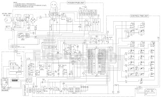
Control circuit diagram and PWB
11) Buzzer drive circuit
The " H / L " signals output from the pin 34 of the microcomputer LSI1 drive the digital transistor Q51 and sound the buzzer BZ1.
12) Fan motor drive circuit
The fan motor has four input terminals and one output terminal.
Vm (CN-C7 pin) : DC voltage input to be the source of motor rotation. (Vm = approx. DC310-340V) Vm created by the power supply circuit is directly input and is constantly applied.
GND (CN-C5 pin) : Reference of the electric potential. All potentials such as Vm, Vcc, Vs, and PG indicate the potential differences with GND.
Vcc (CN-C3 pin) : DC voltage input terminal to be the power supply for the circuit that is built in the fan motor.  During operation, it turns on Q43 and Q44 by outputting the ÉÅHÉÇ signal from the pin 33 of the microcomputer LSI1 of the fan motor, and supplies the potential almost equal to VL to the Vcc terminal (Vcc = approx. DC15V).
Vs (CN-C2 pin) : This input terminal controls the revolution speed of the fan motor (speed instruction signal).
After supplying Vcc during operation, the PWM (x/256EIs) pulse is output from the pin 6 of the microcomputer LSI-1 and smoothed in the circuit consisting of C41, R41-43, Q41 and Q42.  Then it goes through R46 and C43 to supply the DC voltage to the Vs terminal.
(Vs = approx. DC0 E ~ 6V)
When speeding up revolution: the pulse width X is widened Vs voltage is increased
When slowing down revolution: the pulse width X is narrowed Vs voltage is decreased
PG (CN-C1 pin) : Fan motor revolution speed output terminal (feedback signal)
The pulse signal according to the revolution speed is output and it is input into the pin 32 of the microcomputer LSI1 via the circuit consisting of R47, R44, R45, and C42.
The microcomputer recognizes the current revolution speed based on this PG signal, and controls the Vs signal above to keep the speed to the designated level.
13) High-voltage unit drive circuit
The high-voltage unit is the power supply unit that supplies the high voltage to generate ion from the cluster electrode, and it can be activated by inputting AC100V into it.
When the solid state relay SSR1 is turned on, the voltage for commercial power supply drops in the resistors R125 and R126 and approximately AC100V is applied to the high-voltage unit.
During operation, it outputs " L/ H " from the pin 25 of the microcomputer LSI-1, turns on and off Q122 and Q123, and controls and drives SSR1.
14) Relay drive circuit
The anode of the diode D126 on the relay PWB is connected to one line of the cluster electrode, and one side of the relay RY1 contact is connected to the AC input of the high-voltage unit, both via the connector CN-J and
harness. Depending on the mode of the cluster, the output signal from the pin 40 of the microcomputer LSI-1 turns on and off Q121 and Q124, which turns on and off RY1, and switches connection.
In clean mode : " H " is output from the pin 40 of the microcomputer LSI-1 and RY1 is turned off.
In cluster automatic operation ............. It enters the clean mode when the clean sign indicates the air is contaminated (orange or red).
In refresh mode: It outputs " L " from the pin 40 of the microcomputer LSI-1, turns onRY1, and bypasses one side of the cluster electrode and one side of the AC input of the high-voltage unit to direct the flow of electron in one way, thus generating minus ion in large volume compared to plus ion.
In cluster automatic operation ............. It enters the refresh mode when the clean sign indicates the air is clean (green).
15) EEPROM circuit
During operation, data integrated with the operation time of the fan motor (dirtiness of the filter) is read and written into EEPROM (IC1) using the repetitive signals of " H " and " L " that are input and output from the pins 1 and 2 of the microcomputer LSI-1.
4. Special modes
Some of them are not used during servicing, and are described for reference only.
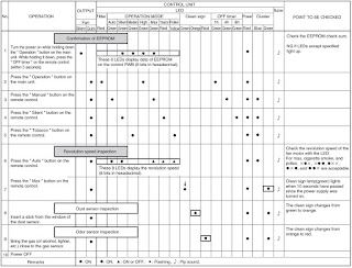
Test mode
This is to test malfunctions of circuits and used to check them in mass production process.
Setting procedure: Turn the power on while holding down the ON Operation selector/OFF TIMER button, and press the " OFF timer " button on the remote control within five seconds.
A pip sound is heard and the unit starts the test mode.
Test mode
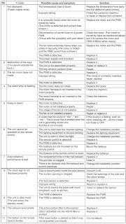
Troubleshooting table
Exploded view

Wednesday, October 03, 2018

LG 42PG60C PLASMA TV Service mode, software update, service adjustments, EDID data download


LG 42PG60C 42PG60C-UA PLASMA TV Service mode, software update, service adjustments, EDID data download
North/Latin America, Europe/Africa, Asia/Oceania
An isolation Transformer should always be used during the servicing of a receiver whose chassis is not isolated from the AC power line. Use a transformer of adequate power rating as this protects the technician from accidents resulting in personal injury from electrical shocks.
It will also protect the receiver and it's components from being damaged by accidental shorts of the circuitry that may be inadvertently introduced during the service operation.
If any fuse (or Fusible Resistor) in this monitor is blown, replace it with the same specified type.
When replacing a high wattage resistor (Oxide Metal Film Resistor, over 1W), keep the resistor 10mm away from PCB.
Adjustments
(1) Because this is not a hot chassis, it is not necessary to use an isolation transformer. However, the use of isolation transformer will help protect test equipment.
(2) Adjustments must be done in the correct order.
(3) The adjustments must be performed in the circumstance of 25±5°C of temperature and 65±10% of relative humidity if there is no specific designation.
(4) The input voltage of the receiver be must kept 110V, 60Hz when adjusting.
(5) The receiver must be operational for about 15 minutes prior to the adjustments.
After receiving 100% white pattern, the receiver must be operated prior to adjustment. (Or 8. White Pattern condition in EZ - Adjust)
2) Enter into White Pattern
- Press POWER ON Key on the Service Remote Control (S R/C)
- Enter the Ez - Adjust by pressing ADJ Key on the Service Remote Control (S R/C).
- Select 7. White Pattern using the CH +/- Key and press the Enter(Y) Key.
Display the 100% Full White Pattern.
[Set is activated HEAT-RUN without signal generator in this mode.]
(If you turn on a still screen more than 20 minutes (Especially Digital pattern (13 CH), Cross Hatch Pattern), an afterimage may occur in the black level part of the screen.)
Auto AV (CVBS) Color Balance
Required Equipment 
(1) Remote controller for adjustment
(2) AV Pattern Generator: 802F Pattern Generator, Master (MSPG-925FS), etc
(Which has NTSC-J Composite Video format output with standard (1.0 Vpp) See Fig)
(3) It is very import to use correct adjustment pattern like Fig.
Method of Auto AV (CVBS) Color Balance
Input the NTSC-J Composite Video (Fig.) into video input.
=> MSPG-925FS Model No: 207 / Pattern No: 65 / NTSC-J
(2) Set the EZ Picture to Daylight mode in Video menu.
(3) Press INSTART key on R/C for adjustment.
(4) Press the G(Vol. +) key operate to set, then it becomes automatically.
(5) Auto-RGB OK means completed adjustment.
* When adjust main picture, sub picture is included.
Auto Component Color Balance
Required Equipment
(1) Remote controller for adjustment
(2) 802F Pattern Generator Which has 720p YPbPr output with Standard (0.7Vpp) See Fig.
(3) It is very important to use correct adjustment pattern like Fig.
Method of Auto Component Color Balance
(1) Input the Component 1280*720p 60Hz signal into Component.
=> MSPG-925FS Model No: 217 / Pattern No: 65
(2) Set the EZ Pictures to Daylight mode in Video menu.
(3) Press INSTART key on R/C for adjustment.
(4) Press the G(Vol. +) key operate To set, then it becomes automatically.
(5) Auto-RGB OK means completed adjustment
Auto RGB Color Balance
Required Equipment
(1) Remote controller for adjustment
(2) 802F Pattern Generator, Master (MSPG-925FS), etc.
(Which has XGA 60Hz PC Format output with standard (0.7Vpp) See Fig.)
(3) It is very import to use correct adjustment pattern like Fig..
Method of Auto RGB Color Balance
(1) Input the PC 1024x768 @ 60Hz into RGB.
=> MSPG-925FS Model No: 60 / Pattern No: 65
(2) Set the EZ Pictures to Daylight mode in Video menu.
(3) Press INSTART key on R/C for adjustment.
(4) Press the G(Vol. +) key operate To set, then it becomes automatically.
(5) Auto-RGB OK means completed adjustment.
RF Color Balance
(1) Input the RF cable
(2) Set the EZ Pictures to Daylight mode in Video menu.
(3) Press INSTART key on R/C for adjustment.
(4) Press the G(Vol. +) key operate To set, then it becomes automatically.
(5) Auto-RGB OK means completed adjustment.
EPLD Download
(1) Test Equipment: PC, Jig for download
(2) Connect the power of VSC B/D.
(3) Execute download program(iMPACK) of PC.
(4) After executing the hot key on the Programmer, click icon
(5) End after confirming.
Connect power.
(2) Connect the jack(No. 1) to PTC Micom.
(3) Connect the USB Cable(No. 2) and computer.
(4) Execute download program(SAP Configuration)
[ (Caution) PTC Download JIG can save Download file in memory by Download Program(SAP Configuration).
Because it has a memory chip inside.
After saving the file, you can download it by just pressing Start button (number 4.)
Download program (SAP Configuration) Execute.
(1) Select HC12.
(2) Specify Algorithm: Select the 9S12dt128_128k.12P file.
(3) Specify S Record: Select the Download file.
(4) Check the check box of Erase Device, Blank Check Device, Porgram Device, Verify Device.
(Caution) Don’t check anywhere except one like picture as shown.
(5) Press “Save Image to Cyclone PRO” button.
And then the file is downloaded to Download JIG from PC.
(6) When Download is finished, you can download the file by pressing “start” button on Download JIG.  At first, you download the file, you should not download it again.
[Each PCB Assy must be checked by Check JIG Set before assembly. (Especially, be careful Power PCB Assy which can cause Damage to the PDP Module.)
POWER PCB Assy Voltage
Adjustment (Va, Vs Voltage Adjustment)
Caution: Set up “RF mode(noise)” before voltage adjustment.
Test Equipment: D.M.M 1EA
Connection Diagram for Measuring.
42” Va Adjustment
1) After receiving 100% Full White Pattern, HEAT RUN.
2) Connect + terminal of D.M.M to Va pin of P811 and connect – terminal to GND pin of P811.
3) After turning VR901, voltage of D.M.M adjustment as same as Va voltage which on label of panel Top/Right.
(Deviation : ±0.5V)
42” Vs Adjustment
1) Connect + terminal of D.M.M to Vs pin of P811 and connect – terminal to GND pin of P811.
2) After turning VR951, voltage of D.M.M adjustment as same as Vs voltage which on label of panel Top/Right.
(Deviation : ±0.5V)
EDID(The Extended Display Identification Data)/DDC (Display Data Channel) Download
It is the feature to implement the “Plug and Play” which automatically reconfigures the user’s environment to directly use by exchanging information without any command directly to the PC or the monitor by the user, which is established by
the VESA
HDMI EDID Data Input
(1) Required Test Equipment
1) PC, Jig for adjusting DDC. (PC serial to D-sub Connection equipment)
2) S/W for writing DDC(EDID data write & read)
3) D-Sub cable
4) Jig for HDMI Cable connection
Preparation for Adjustments & Setting of Device
1) Set devices as below and turn on the PC and JIG.
2) Open S/W for writing DDC (EDID data write & read). (operated in DOS mode)
Download Method
(1) Set devices as above and turn on the PC and JIG.
(2) Execute DDC Program (EDID data write & read).
(3) Select the EDID data of the said model by selecting Model > Open at the menu.
(4) Check the item(s) to download from the <Test processing > items.
1) HDMI & RGB: Digital & Analog Check
2) (Only)HDMI: Check only the digital
(5) Press ESC (Cancel mode) -> F8 (Auto mode). (Set ‘Auto Detecting‘)
(6) Connect the said signal cable to the set.
(7) Make sure that the window “Perform the write operation?“
is displayed.
(8) Press the Enter key or the space key to download.
(9) After checking the ’OK’ message after downloading, disconnect the connected cable.
EDID DATA for PA64C
Adjust to equalize the white color caused by the module deviation
Required Test Equipment
(1) Color Analyzer: CA-100+(CH 10), CA-100(CH10), CA- 210U(CH 10)
(2) Computer for adjusting (necessary for the automatic adjustment, possible to communicate with the RS-232C)
(3) Remote controller for adjusting
* Use the instrument with the matrix compensated by the CS- 1000 as the color analyzer.
Adjustment of White Balance
* Operate the Zero-calibration of the CA-100, then attach sensor to PDP module surface when you adjust.
* Manual adjustment is also possible by the following sequence.
(1) Enter ‘Ez - Adjust’ by pressing ADJ KEY on the Service Remote Control.
(2) Select "8. WHITE PATTERN" using CH +/- Key and HEAT RUN at least 30 minutes by pressing the ENTER Key.
(3) Receive the Window pattern signal from Digital Pattern Generator. (AV Input: connect the ‘HDMI’)
(4) After attaching sensor to center of screen, select ‘5. White Balance’ of ‘Ez - Adjust’ by pressing the ADJ KEY on the Service R/C. Then enter adjustment mode by pressing the Right KEY (G) .
(5) Adjust the High Light using R Gain/G Gain/B Gain.(Cool).  Adjust the High Light using R Gain/G Gain/B Gain.
(Medium).
Adjust the Hight Light using R Gain/G Gain/B Gain.(Warm).
(6) Adjust using Volume +/- KEY.
(7) After adjustment is complete, exit the adjustment mode by pressing the ADJ KEY.
High Level: 216gray
[Cool]
X; 0.276±0.002 Y; 0.283±0.002
Color temperature: 11000°K±1000°K
[Medium]
X; 0.285±0.002 Y; 0.293±0.002
Color temperature: 9300°K±1000°K
[Warm]
X; 0.313±0.002 Y; 0.329±0.002
Color temperature: 6500°K±1000°K
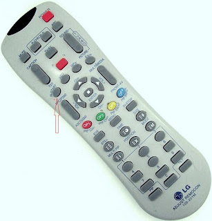
To enter and to adjust the data values, you should have a special remote control [service remote control].  You can buy it either any authorized service center for LG, or by online electronic spare part selling shops. Will look like this. Note its number, and place the order.
It has a special button "Instart".  You should press it to enter the service mode.  This button is not with your user remote control.  This remote control can be used to enter the service mode to any model LG sets.
Adjust remote control for LG - 105-201M
LG Support:
CANADA: LG Electronics Canada, Inc. 550 Matheson Boulevard East Mississauga, Ontario L4Z 4G3.
USA : LG Customer Interactive Center, P.O.Box 240007, 201 James Record Road Huntsville, AL 35824 Digital TV Hotline 1-800-243-0000.