How to disassemble, hot to upgrade, EDID data download, Troubleshooting, circuit diagram - DELL 2005FPW-20 inch LCD colour monitor
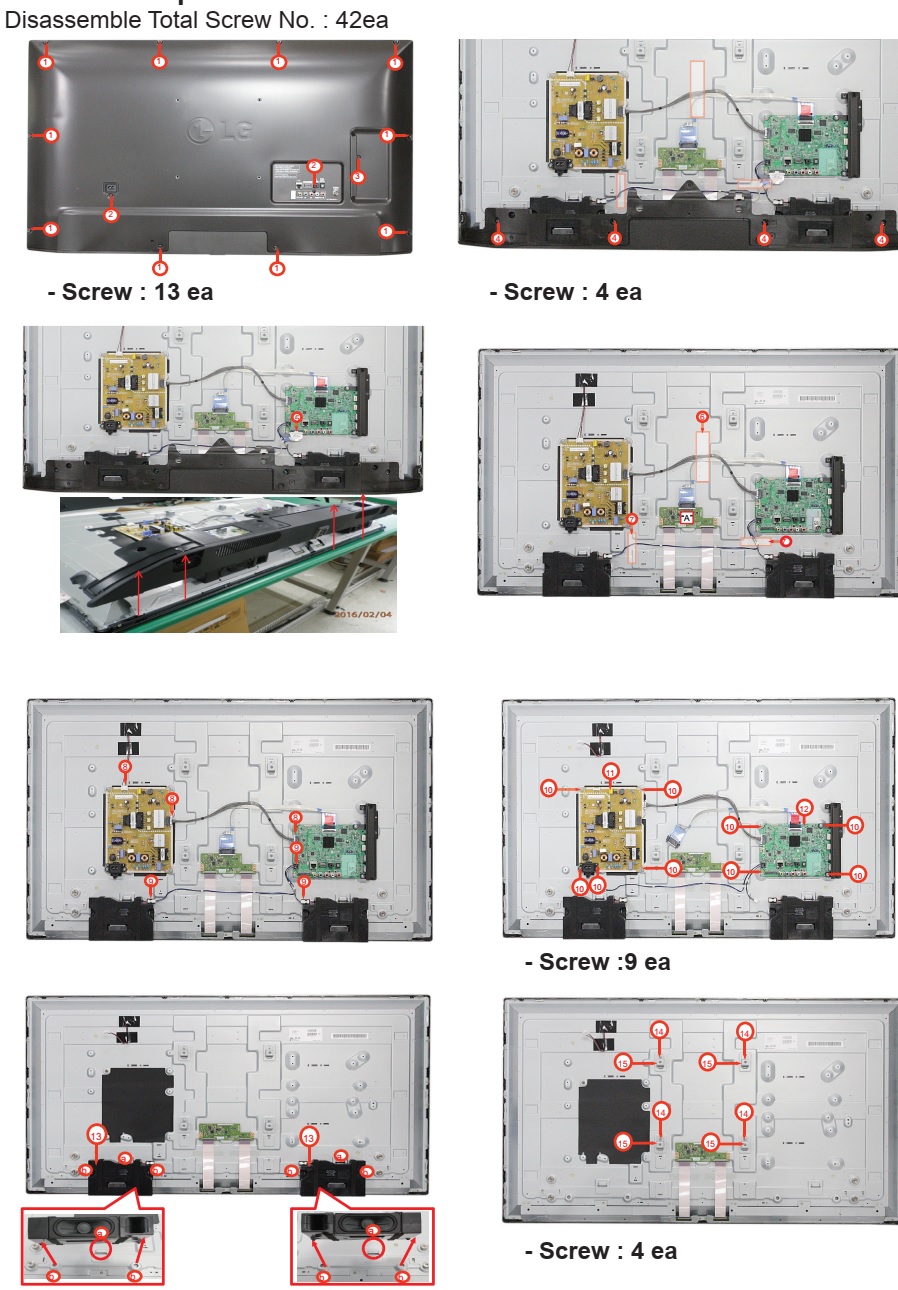
Disassembly
* Remove
the screws.
** Lift
central inside edge of Cabinet upward with fingertip then latch will be
departed. (This time take care so that
do not give damage on the module surface.)
*** Progress
to left and lift cabinet furtively and extracts latch.
**** Progress
to right and extracts cabinet side latch by same method.
****** Progress
to bottom.
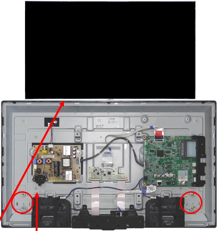
Warning : if you lift cabinet up, power connector lead may be disconnected or damaged.) Refer to the small picture.
Warning : if you lift cabinet up, power connector lead may be disconnected or damaged.) Refer to the small picture.
******* Turn
upside down and then lift the back cover ass'y up.


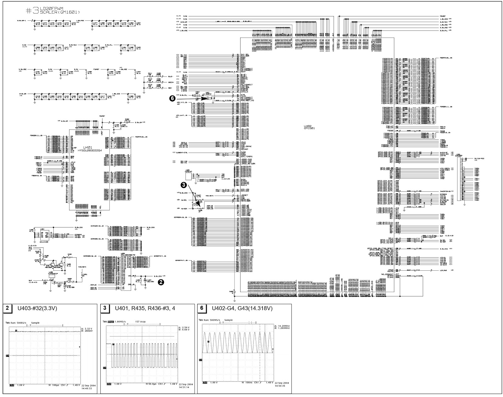
Video Controller Part & Display Data Transmitter Part.
This part amplifies the level of video signal for the digital conversion and converts from the analogue video signal to the digital video signal using a pixel clock.
The pixel clock for each mode is generated by the PLL.
The range of the pixel clock is from 25MHz to 147MHz.
This part consists of the Scaler, Flash-ROM IC which stores program data, Reset IC.
The Scaler gets the video signal converted analog to digital, interpolates input to 1680 x1050 resolution signal and outputs 8-bit R, G, B signal to transmitter.
Especially pre-amp / ADC / Video controller/ Transmitter are merged to one chip "Gm1501" by Genesis.
This part transmit digital signal from the Scaler to the receiver of module’s.
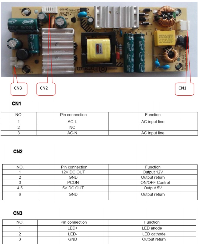
Power Part
This part consists of the two 3.3V and one 2.5V and one 1.8Vregulators to convert power which is provided 12V in Power Board V is provided for LCD Panel.(Only LPL)
5V in Power Board V is provided for LCD Panel.(Only AUO)
12V in Power Board V is provided for Inverter Part.
Also, 5V is converted 3.3V, 2.5V and 1.8V by regulator. Converted power is provided for IC in the main board.
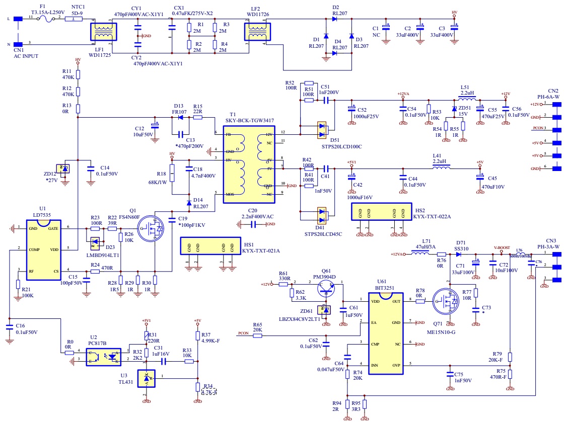
Operation description (Power)
1. EMI
components.
This part contains of EMI components to comply with global marketing EMI standards like FCC,VCCI CISPR, the circuit included a line-filter, across line capacitor and of course a primary protection fuse.
2. Input rectifier and filter.
This part function is for transfer the input AC voltage to a DC voltage through a bridge rectifier and a bulk capacitor.
3. Energy Transfer.
This part function is for transfer the primary energy to secondary through a power transformer.
4. Output rectifier and filter.
This part function is to make a pulse width modulation control and to provide the driver signal to power switch, to adjust the duty cycle during different AC input and output loading condition to achieve the dc output stabilized, and also the over power protection is also monitored by this part.
5. Photo-Coupler isolation.
This part function is to feed back the DC output changing status through a photo - transistor to primary controller to achieve the stabilized dc output voltage.
6. Signal collection.
This part function is to collect the any change from the DC output and feed back to the primary through photo transistor.
7. Inverter
The inverter converts DC12V to AC 840Vrms and operate back-light lamp of module.
This part function is to collect the any change from the DC output and feed back to the primary through photo transistor.
7. Inverter
The inverter converts DC12V to AC 840Vrms and operate back-light lamp of module.
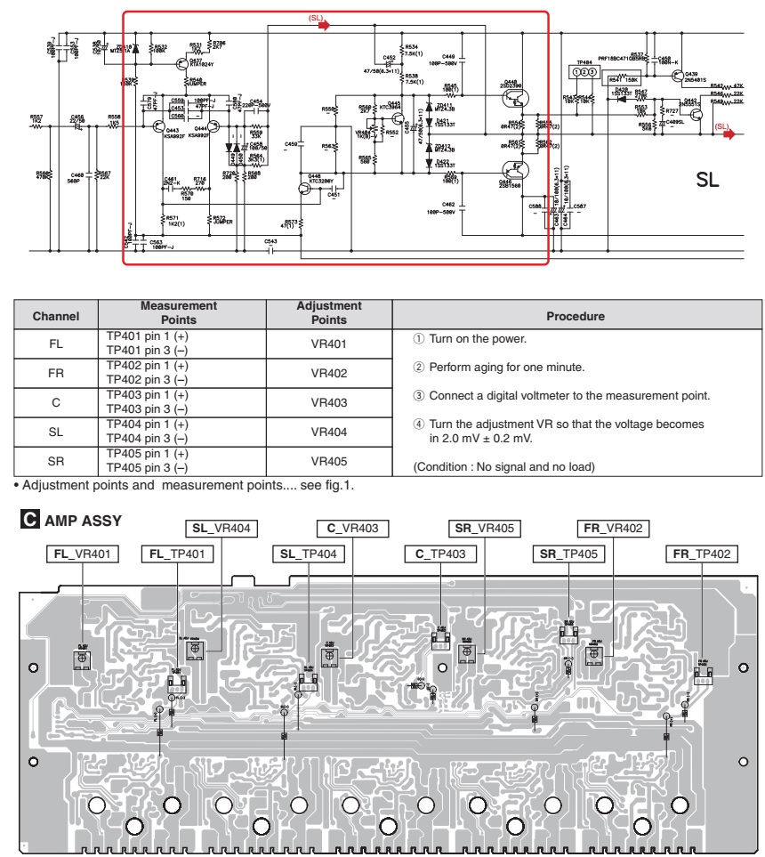
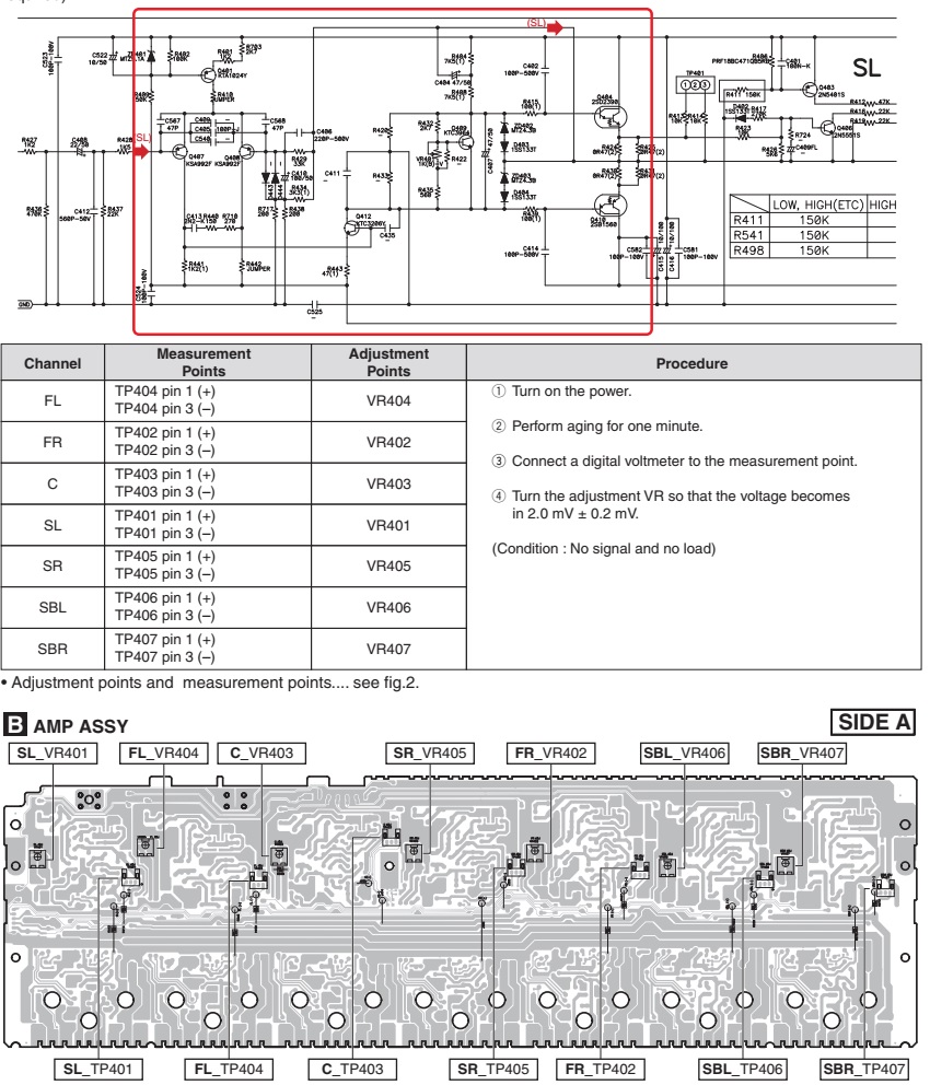
Adjustments
Windows
EDID V1.0 User Manual
Operating
System: MS Windows 98, 2000, XP
Port Setup: Windows 98 > don’t need setup
Port Setup: Windows 98 > don’t need setup
This program is available to LCD Monitor only.
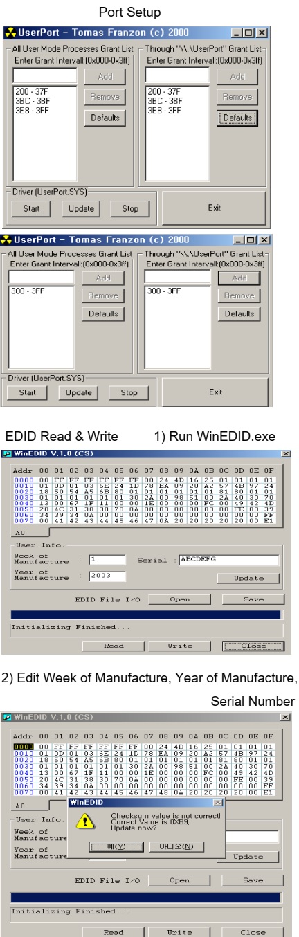
Port Setup
a) Copy “UserPort.sys” file to “c:\WINNT\system32\drivers” folder
b) Run Userport.exe.
a) Copy “UserPort.sys” file to “c:\WINNT\system32\drivers” folder
b) Run Userport.exe.
c)
Remove all default number.
d) Add 300-3FF.
d) Add 300-3FF.
e)
Click Start button.
f) Click Exit button.
f) Click Exit button.
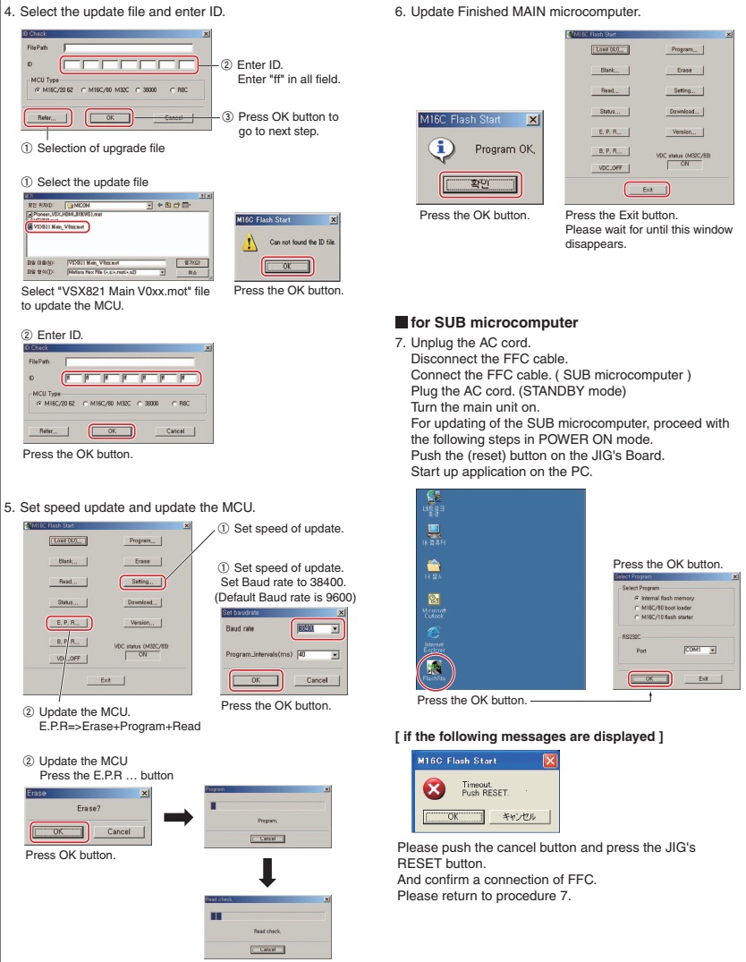
EDID Read & Write
1) Run WinEDID.exe
1) Run WinEDID.exe
Edit
Week of Manufacture, Year of Manufacture, Serial Number.
a) Input User Info Data.
b) Click “Update” button.
c) Click “Write” button.
a) Input User Info Data.
b) Click “Update” button.
c) Click “Write” button.
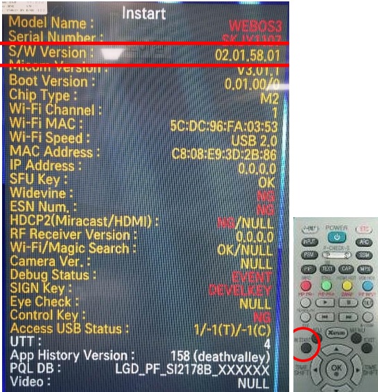
Service mode
1. Turn
off the power switch at the front of the display panel.
2) Wait for about 5 seconds and then press MENU, PLUS, POWER key.
3) The SVC OSD menu disply contains additional menus that the User OSD menu as described below.
a) WB Adjust: To adjust ADC cutoff/gain.
Use Black pattern for cutoff adjustment and press Menu.
2) Wait for about 5 seconds and then press MENU, PLUS, POWER key.
3) The SVC OSD menu disply contains additional menus that the User OSD menu as described below.
a) WB Adjust: To adjust ADC cutoff/gain.
Use Black pattern for cutoff adjustment and press Menu.
If the number changes
to 1, cutoff adjustment is OK.
Use full white pattern for gain adjustment and press Menu.
Use full white pattern for gain adjustment and press Menu.
If the number
changes to 2, gain adjustment is OK.
b) NVRAM Init : EEPROM initialise (24C16).
c) Reset Time : Reset elapsed time.
d) Aging: Select Aging mode (On/Off).
e) WProtect : To enable write protection.(24c02)
f) Blue : to set the R/G/B - 9300K value manually.
g) Red: to set the R/G/B - 5700K value manually.
h) Normal: to set the R/G/B - 6500K value manually.
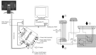
Cable Connection

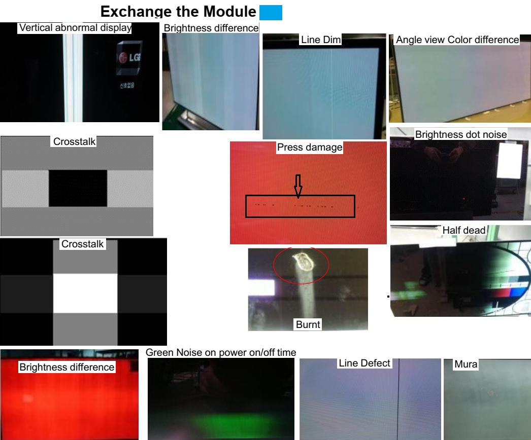
Troubleshooting chart


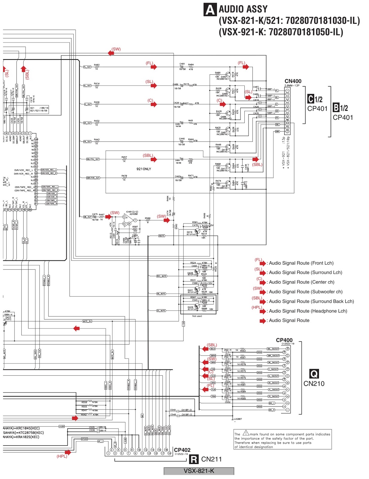
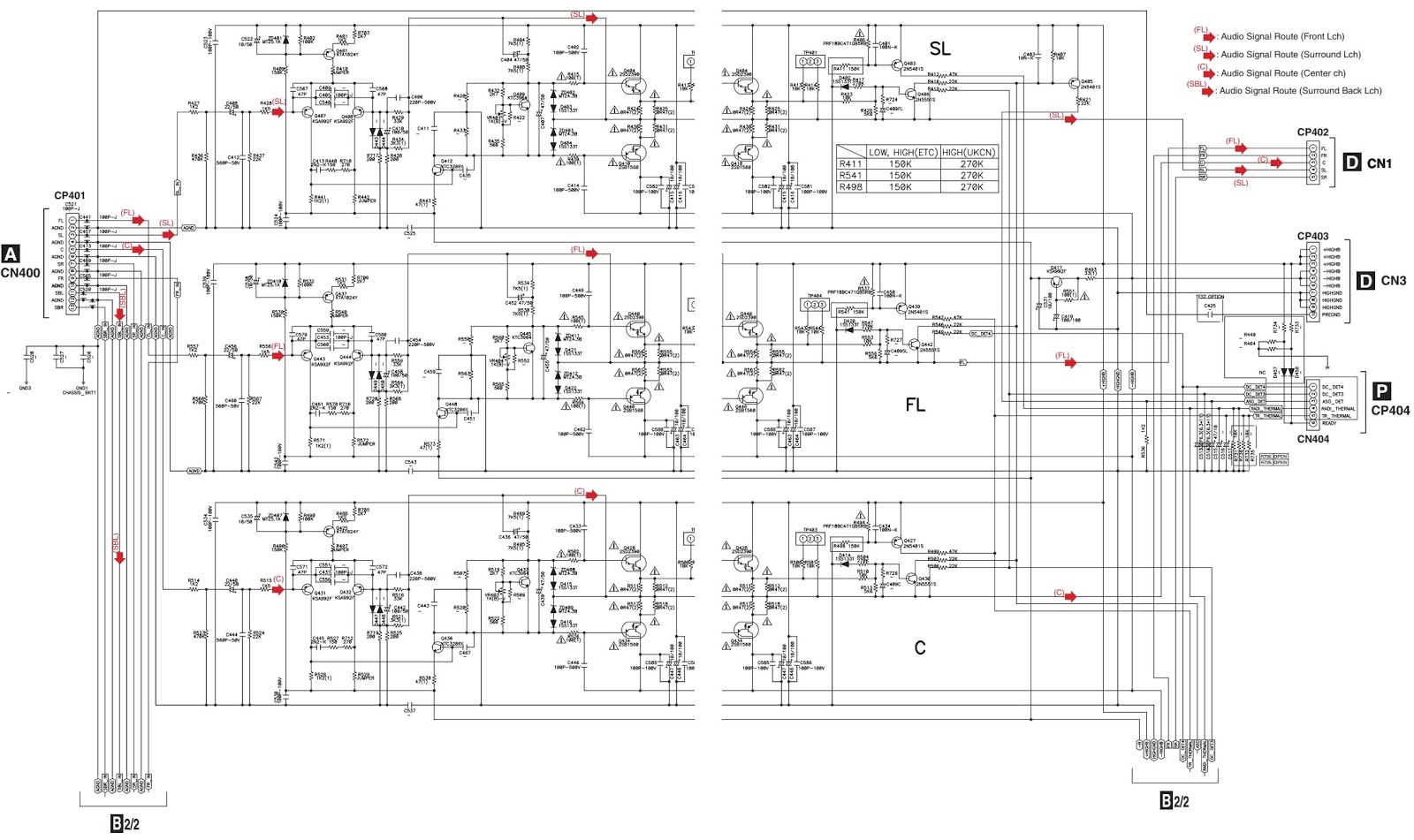
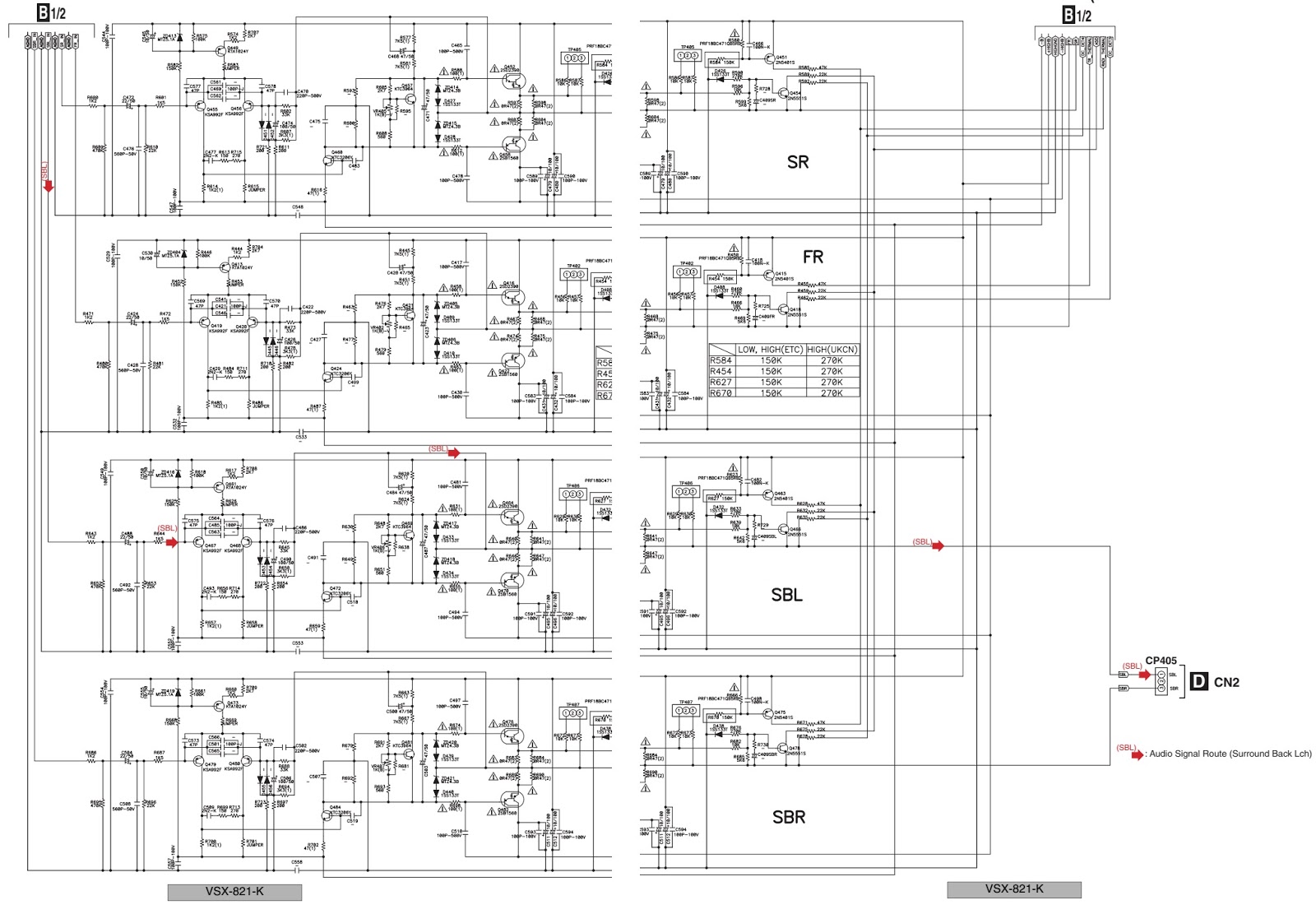
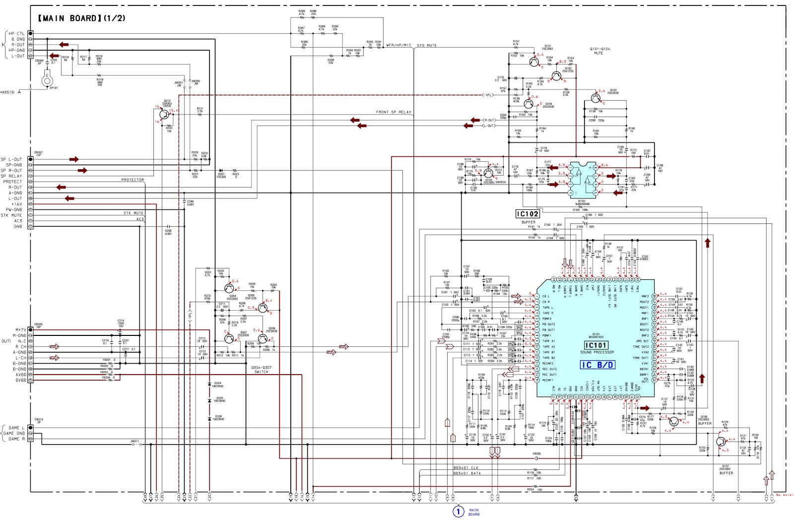
Schematic


Electro help - Service Modes, Circuit Diagrams, Firmware Update procedure, Disassemble procedure, Universal remote control set-up codes, Troubleshooting and more....