Sony
AZ3FK Chassis


KDL-32EX340
RM-YD080 US/CND
KDL-32EX340 RM-YD080 MX/LA
KDL-32EX340 RM-YD080 MX/LA
KDL-42EX440
RM-YD080 US/CND
KDL-42EX440 RM-YD080 MX/LA
KDL-42EX441 RM-YD080 US
KDL-42EX440 RM-YD080 MX/LA
KDL-42EX441 RM-YD080 US
Updates and adjustments
The
models in this manual utilize a “generic” type of Main Board, therefore a software
update must be performed and certain service adjustment settings must be
changed or confirmed whenever the Main Board, LCD Panel or TCON Board is
replaced.
There are 2 reasons for updating the software on the TVs:
Software updates for customers
These updates are for enhancements or improvements that have been made to the software after the TV was released.
These updates are accessed by the customer from the Sony Support Site at http://esupport.sony.com.
Software update for service technicians
These updates are specifically for servicers to use during a service call and are only available on the Sony Authorized Servicer Portal.
Software updates for customers
The subject of software updates is very important. The televisions of today have advanced to the point where they are not simply a television anymore.
They are evolving into devices that are designed to integrate with numerous other devices found in the home. Some examples are: portable audio and video devices, still cameras, home computer networks and accessing the internet to name a few.
Communications with these varying devices requires that the television be compatible with varying communications protocols. Although standards are detailed for each of these protocols, the real world dictates that occasional errors may occur that could prevent devices from operating or communicating properly.
Keeping the software in the television up-to-date is a procedure that is normally handled by the owner of the television. Most customers who own computers and other digital devices are familiar with and are accustomed to updating the software in their products. If a customer contacts the Sony Customer Support Center and it is deemed to be correctable with a software update, the issue is handled at the customer level.
Software updates can be performed by:
Customer Manual Downloads
Software updates can be accessed by the customer from the Sony Support Site at http://esupport.sony.com where they can be downloaded and placed on a USB thumb drive to be loaded onto the TV. The instructions for downloading the software file vary from chassis to chassis and sometimes from model to model. The customer is provided with the instructions to properly format the USB thumb drive, unzip the file, and the procedures for loading the software into the television.
Software updates for service technicians
Replacement Main Boards are now stocked with basic software. Once the replacement board is installed in the TV, the most current software needs to be installed using a USB thumb drive containing the necessary software.
This new method of supplying Main Boards significantly reduces the complexity of replacing the Main Boards. Information about the LCD panel is stored on the TCON circuits. This information is automatically loaded onto the Main Board when the TV is powered up. With the correct software version the Main Board and/or the TCON can be replaced more efficiently. The software update and procedures for the software installation are located on the Sony Authorized Service Portal.
Software update responsibility
Software updates are designed to be performed by the customer. Warranty repairs in which the issue can be resolved by a software update are not reimbursable. Most issues involving software updates are handled by the customer service center and should not be directed to an authorized service center. It is the responsibility of the servicer to prevent service calls for issues that involve software updates. Exceptions to this are certain cases whereby the customer is unable or unwilling to perform the task. In this situation, the servicer will be notified and receive the proper authorization for reimbursement.
It is the servicer’s responsibility, however, to make certain that any TV requiring a legitimate service is running the latest software version and to install it if necessary.
Checking the software version
The easiest way to check the version of software that is currently on the TV is to access the Contact Sony screen by using the customer menu.
The easiest way to check the version of software that is currently on the TV is to access the Contact Sony screen by using the customer menu.

Examples of software correctable symptoms
Always check the Sony Authorized Servicer Portal for any known and/or listed issues that are software related. Most symptoms that are correctable by software updates involve communications issues with other devices or minor glitches in the operation of a specific function. Below is a list of some of the symptoms that may be corrected with a software update:
* Fluctuations in picture brightness
* Intermittent picture freezing or noise
* Problems with certain inputs (especially HDMI)
* Intermittent or distorted audio
* Erratic remote control operation
* Unit turns on and off by itself
* Loss of color
* Internet connectivity (internet models only)
* Certain features not working correctly (photo or video file viewing)
After
replacing the Main Board, LCD Panel or TCON Board, you MUST UPDATE the SOFTWARE
to the latest version. Instructions for updating the software are included with
the software package on the Sony Authorized Service Portal websiteAlways check the Sony Authorized Servicer Portal for any known and/or listed issues that are software related. Most symptoms that are correctable by software updates involve communications issues with other devices or minor glitches in the operation of a specific function. Below is a list of some of the symptoms that may be corrected with a software update:
* Fluctuations in picture brightness
* Intermittent picture freezing or noise
* Problems with certain inputs (especially HDMI)
* Intermittent or distorted audio
* Erratic remote control operation
* Unit turns on and off by itself
* Loss of color
* Internet connectivity (internet models only)
* Certain features not working correctly (photo or video file viewing)
Accessing service adjustment mode
To access Service Mode, please follow the next instructions:
1. TV must be in Standby mode.
2. Press the following buttons on the Remote Commander within a second of each other:
DISPLAY > Channel 5 > Volume + > POWER
To access Service Mode, please follow the next instructions:
1. TV must be in Standby mode.
2. Press the following buttons on the Remote Commander within a second of each other:
DISPLAY > Channel 5 > Volume + > POWER
Remote control: RM-YD080
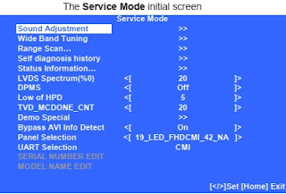
3.
The Service Mode initial screen, will be displayed.
4.
Do one of the following:
a. Proceed to Completing Service Requirements when Replacing the Main Board.
b. Proceed to Completing Service Requirements when Replacing the LCD Panel.
a. Proceed to Completing Service Requirements when Replacing the Main Board.
b. Proceed to Completing Service Requirements when Replacing the LCD Panel.
Completing service requirements when replacing the main board
The following must be performed after replacing the Main Board to ensure
that all of the features for the TV will be available.
View the Status Information
Select the Panel ID Code
Add the Serial Number
Add the Model Name.
The following must be performed after replacing the Main Board to ensure
that all of the features for the TV will be available.
View the Status Information
Select the Panel ID Code
Add the Serial Number
Add the Model Name.

Viewing the status information
After replacing the Main Board you MUST UPDATE the SOFTWARE to the latest version.
Whenever the Main Board is replaced, the software must be updated so that the new board syncs with the LCD Panel. If a message displays indicating the latest software is already installed, proceed to Resetting the LCD Panel to Update the Software.
Verify the latest software is installed before proceeding to the service adjustments.
Press (Down) until Status Information is selected.
Then
press (Righty) to view the Status Information screen.
The latest version is displayed as shown:
The latest version is displayed as shown:
Selecting the panel id code caution: you must select the correct
panel id code for the picture to display properly.
Verify before proceeding to the next step:
Verified the Status Information
Press (Down) to select Panel Selection
Verify before proceeding to the next step:
Verified the Status Information
Press (Down) to select Panel Selection
Using
the table below, press (Left) or
(Right) to select the correct Panel Code
for the Panel ID.
CAUTION:
If you do not select the correct Panel ID code, the picture may not display.
Verify the Panel ID is correct before proceeding to the next step.
Proceed to Adding the Serial Number.
Verify the Panel ID is correct before proceeding to the next step.
Proceed to Adding the Serial Number.

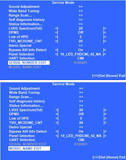
Adding the serial number
Verify before proceeding to the next step:
Verified Status Information
Selected the Panel ID Code
Locate the Serial Number for the TV on the side of the Rear Cover of the TV.
Verify before proceeding to the next step:
Verified Status Information
Selected the Panel ID Code
Locate the Serial Number for the TV on the side of the Rear Cover of the TV.
Press
(Down) until SERIAL NUMBER EDIT is selected.
Press
(Right) to be able to select the first digit.
CAUTION: The Serial Number can only be selected once.
Be sure to verify the information is correct before saving the changes.
CAUTION: The Serial Number can only be selected once.
Be sure to verify the information is correct before saving the changes.
Press Left) or (Right) until the first number
of the Serial Number of the TV displays.
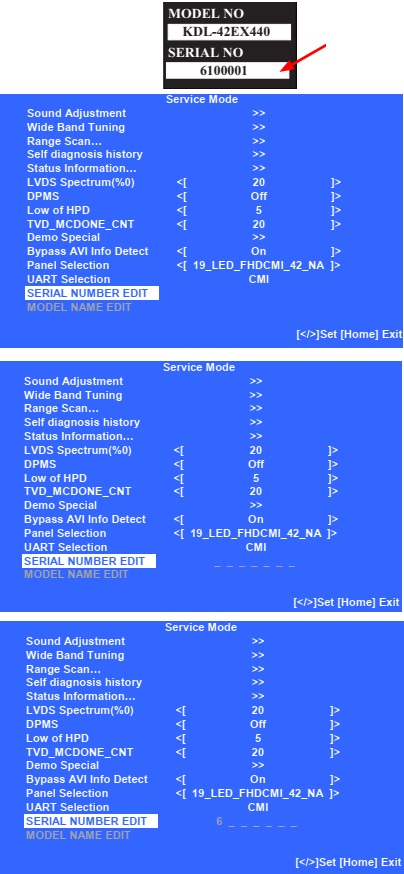
Continue
to use (Right) and (Up) or (Down) to enter the remaining digits of the Serial
Number.
Verify
the Serial Number is correct before proceeding to the next step.
When the complete Serial Number is displayed, press (+) .
When the confirmation screen displays, press (Left) to select YES, and then press (+) .
Proceed to Adding the Model Name.
When the complete Serial Number is displayed, press (+) .
When the confirmation screen displays, press (Left) to select YES, and then press (+) .
Proceed to Adding the Model Name.
adding the model name
Verify before proceeding to the next step:
Verified Status Information
Selected the Panel ID Code
Added the Serial Number
Press (Down) until MODEL NAME EDIT is selected.
Verify before proceeding to the next step:
Verified Status Information
Selected the Panel ID Code
Added the Serial Number
Press (Down) until MODEL NAME EDIT is selected.

Press
(Right) to be able to select the first character.
CAUTION: The Model Name can only be selected once.
Be sure to verify the information is correct before saving the changes.
CAUTION: The Model Name can only be selected once.
Be sure to verify the information is correct before saving the changes.
Press
(Up) or (Dn) until the first character of the Model Name of the TV displays
Continue
to use (Right) and (Up) or (Dn) to enter the remaining digits of the Model Name
Verify
the Model Name is correct before proceeding to the next step.
When the complete Model Name is displayed, press (+) .
When the confirmation screen displays, press to select YES, and then press (+) .
Press POWER to exit Service Mode.
When the complete Model Name is displayed, press (+) .
When the confirmation screen displays, press to select YES, and then press (+) .
Press POWER to exit Service Mode.

Completing service requirements when replacing the lcd panel
The following must be performed after replacing the LCD Panel.
NOTE: The TCON Board for the KDL-32EX340 model is internal and cannot be replaced.
View the Status Information
Verify the Panel ID Code
Reset the Panel Operation Time
1. TV must be in Standby mode.
2. Press the following buttons on the Remote Commander
within a second of each other:
DISPLAY > Channel 5 > Volume + > POWER
After
replacing the LCD Panel or TCON Board you MUST UPDATE the SOFTWARE to the
latest version. Verify the latest software is installed before proceeding to
the service adjustments.
If
the latest software is installed, proceed to Verifying the Panel ID Code.
If the latest software is not installed, update the software and then proceed to Verifying the Panel ID Code.
If the latest software is not installed, update the software and then proceed to Verifying the Panel ID Code.
Verifying the panel id code
Press (Dn) to select Panel Selection.
Press (Dn) to select Panel Selection.
Using
the table below, verify the correct Panel Code for the Panel ID
Proceed
to Resetting the Panel Operation Time.

Resetting panel operation time
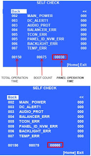
On the Self Check screen, identify the Panel Operation Time location.
On the Self Check screen, identify the Panel Operation Time location.
Press 7 > 0
Verify Panel Operation
Time has been changed to 00000
To
exit the Self Check, press HOME.

Accessing factory adjustment mode
To access, please follow the next instructions:
1. TV must be ON.
2. Press the following buttons on the Remote Commander within a second of each other:
To access, please follow the next instructions:
1. TV must be ON.
2. Press the following buttons on the Remote Commander within a second of each other:
NOTE:
The instructions to access Factory Mode are NOT THE SAME as the Service Mode
procedure.
Adjusting the color temperature
The default White Balance data values are set for optimal viewing. The following instructions are for technicians who have been requested to customize calibrations for their customers.
Using (Down), scroll down to select Color Temp.
The default White Balance data values are set for optimal viewing. The following instructions are for technicians who have been requested to customize calibrations for their customers.
Using (Down), scroll down to select Color Temp.
Press
to access Color Temp adjustments.
Press
the or buttons to select the Color Temp type. (Cool, Neutral, Warm1 or Warm2).
After the correct Color Temperature is selected, press to select the temperature type that needs to be modified.
After the correct temperature type is selected, press to increase the data value or press to decrease the data value.
Complete the data value adjustments to the remaining temperature items within the selected temperature type.
NOTE: Changes to the data value must be saved within the temperature type selected before making changes to one of the other temperature types.
To
save the changes, press (Dn) to select Data Backup
Press
(Right) to select the option: W/B and press (+) .
Do one of the following:
a. To make changes to one of the other temperature types,
repeat steps.
b. To exit Factory mode, press HOME.
Do one of the following:
a. To make changes to one of the other temperature types,
repeat steps.
b. To exit Factory mode, press HOME.


