Applicable to: 43PUH6101 / 88, 43PUS6101 / 12, 43PUT6101 / 12/60, 43PUS6201
/ 12, 43PUT6201 / 12, 49PUH6101 / 88, 49PUS6101 / 12, 49PUT6101 / 12/60,55PUH6101 / 88, 55PUS6101 / 12, 55PUT6101 / 12/60, 55PUS6201 / 12,
55PUT6201 / 12, 65PUS6121 / 12, 65PUT6121 / 12
Display Option Code Selection
When after an SSB or display exchange, the display option code is not set properly, it will result in a TV with “no display”.
Therefore, it is required to set this display option code after such a repair.
To do so, press the following key sequence on a standard RC transmitter: “062598” directly followed by MENU and “xxx”, where “xxx” is a 3 digit decimal value of the panel type. When the value is accepted and stored in NVM, the set will switch to Stand-by, to indicate that the process has been completed.
During this algorithm, the NVM-content must be filtered, because several items in the NVM are TV-related and not SSB related (e.g. Model and Prod. S/N). Therefore, “Model” and “Prod. S/N” data is changed into “See Type Plate”. In case a call centre or consumer reads “See Type Plate” in CSM mode.
Software Identification, Version, and
ClusterWhen after an SSB or display exchange, the display option code is not set properly, it will result in a TV with “no display”.
Therefore, it is required to set this display option code after such a repair.
To do so, press the following key sequence on a standard RC transmitter: “062598” directly followed by MENU and “xxx”, where “xxx” is a 3 digit decimal value of the panel type. When the value is accepted and stored in NVM, the set will switch to Stand-by, to indicate that the process has been completed.
During this algorithm, the NVM-content must be filtered, because several items in the NVM are TV-related and not SSB related (e.g. Model and Prod. S/N). Therefore, “Model” and “Prod. S/N” data is changed into “See Type Plate”. In case a call centre or consumer reads “See Type Plate” in CSM mode.
The software ID, version, and cluster will be shown
in the main menu display of SAM, and CSM.
The screen will show: “AAAAAB-XXX.YYY.MMM.TTT”, where: • AAAAA is the chassis name: TPL161E.
• B is the region indication: E = Europe, A = AP/China, U = NAFTA, L = LATAM.
The screen will show: “AAAAAB-XXX.YYY.MMM.TTT”, where: • AAAAA is the chassis name: TPL161E.
• B is the region indication: E = Europe, A = AP/China, U = NAFTA, L = LATAM.
•
X is the main version number: this is updated with a major change of
specification (incompatible with the previous software version). Numbering will
go from 1 - 99 and AA - ZZ.
- If the main version number changes, the new version number is written in the NVM.
- If the main version number changes, the default settings are loaded.
• YYY is the sub version number: this is updated with a minor change (backwards compatible with the previous versions). Numbering will go from 000 - 999.
- If the sub version number changes, the new version number is written in the NVM.
- If the NVM is refreshed, the software identification, version, and cluster will also be written to NVM.
Service Alignment Mode (SAM) [Service Mode]
To
activate SAM, use one of the following methods:
• Press the following key sequence on the remote control transmitter: “062596”, directly followed by the “INFO/OK” button. Do not allow the display to time out between entries while keying the sequence.
After entering SAM, the following items are displayed, with “SAM” in the upper right corner of the screen to indicate that the television is in Service Alignment Mode.
How to Navigate
• In the SAM menu, select menu items with the UP/DOWN keys on the remote control transmitter. The selected item will be indicated. When not all menu items fit on the screen, use the UP/DOWN keys to display the next/previous menu items.
• With the “LEFT/RIGHT” keys, it is possible to:
– (De) activate the selected menu item.
– (De) activate the selected sub menu.
– Change the value of the selected menu item.
• When you press the MENU button once while in top level SAM, the set will switch to the normal user menu (with the SAM mode still active in the background).
• Press the following key sequence on the remote control transmitter: “062596” directly followed by the “Home/Menu” button to switch to (do not allow the display to time out between entries while keying the sequence).
How to Store SAM Settings
To store the settings changed in SAM mode (except the RGB Align settings), leave the top level SAM menu by using the POWER button on the remote control transmitter or the television set. The mentioned exceptions must be stored separately via the STORE button.
How to Exit SAM
Use one of the following methods:
• Switch the set to STANDBY by pressing the mains button on the remote control transmitter or the television set.
• Via a standard RC-transmitter, key in “00” sequence.
Note: When the
TV is switched “off” by a power interrupt while in SAM, the TV will show up in
“normal operation mode” as soon as the power is supplied again. The error
buffer will not be cleared.
How to Activate the Factory mode
To activate the Factory mode, use the following method:
• Press the following key sequence on the remote control transmitter: from the “menu/home” press “1999”, directly followed by the “Back/Return” button. Do not allow the display to time out between entries while keying the sequence.
After entering the Factory mode, the following items are displayed,
How to Exit the Factory mode
Use one of the following methods:
• Select EXIT_FACTORY from the menu and press the “OK” button.
Note: When the TV is switched “off” by a power interrupt, or normal switch to “stand-by” while in the factory mode, the TV will show up in “normal operation mode” as soon as the power is supplied again. The error buffer will not be cleared.
Customer Service Mode (CSM)
The Customer Service Mode shows error codes and information on the TVs operation settings. The call centre can instruct the customer (by telephone) to enter CSM in order to identify the status of the set. This helps the call centre to diagnose problems and failures in the TV set before making a service call.
The CSM is a read-only mode; therefore, modifications are not possible in this mode.
•
Possibility to use “CH+” or “CH-” for channel surfing, or enter the specific
channel number on the RC.
How to Activate CSM
To activate CSM, press the following key sequence on a standard remote control transmitter: “123654” (do not allow the display to time out between entries while keying the sequence).
After entering the Customer Service Mode, the following items are displayed.
Note: Activation of the CSM is only possible if there is no (user) menu on the screen.
How to Exit CSM
To exit CSM, use one of the following methods.
• Press the MENU/HOME button on the remote control transmitter.
• Press the POWER button on the remote control transmitter.
• Press the POWER button on the television set.
To exit CSM, use one of the following methods.
• Press the MENU/HOME button on the remote control transmitter.
• Press the POWER button on the remote control transmitter.
• Press the POWER button on the television set.
Software Upgrading
It
is possible for the user to upgrade the main software via the USB port. This
allows replacement of a software image in a stand alone set. A description on
how to upgrade the main software can be found in the DFU or on the Philips/support website.
Preparing a portable memory for software upgrade
The following requirements have to be met:
1. A personal computer connected to the internet.
2. An archive utility that supports the ZIP-format (e.g. WinZip for Windows or Stufflt for Mac OS).
3. A FAT formatted USB memory stick (preferably empty).
Note:
1. Only FAT/DOS-formatted memory sticks are supported.
2. Only use software update files that can be found on the philips web site.
Check the current TV software version
Before starting the software upgrade procedure, it is advised to check that what the current TV software:
1. Press the “1 2 3 6 5 4” button on the remote control to enter the CSM mode.
2. Use the up/down cursor keys to select “Current Main Software”.
If the current software version of the TV is the same as the latest update file found on philips/support website. It is not necessary to update the TV software.
Download the latest software
1. Open the internet page philips/support website.
2. Find information and software related to the TV.
3. Select the latest software update file and download it to the PC.
4. Insert the USB memory stick into one of the USB ports of the PC.
5. Decompress the downloaded ZIP file and copy it to the root directory of the USB flash drive.
Update the TV software
1. Turn the TV on and wait for it to boot completely.
2. Insert the USB memory stick that contains the software update files in one of the TV’s USB ports.
3. The TV will detect the USB memory stick automatically.
Then a window jumps out.
Note: If the USB flash drive is not detected after power up, disconnect it and re-insert it.
4. Select [Update] and press OK.
5. To proceed, In next menu select [Start] and press OK to start software updates.
6.
Upgrading will now begins and the status of the updating progress will be
displayed.
7. When the TV software is updated. Remove your USB flash drive, then select [Restart] and press OK to restart the TV.
Note:7. When the TV software is updated. Remove your USB flash drive, then select [Restart] and press OK to restart the TV.
• Do not remove the USB flash drive
during the software update.
• If a power failure occurs during the update, do not remove the USB flash drive from the TV. The TV will continue the software update as soon as the power comes up again.
• If an error occurs during the update retry the procedure or contact the dealer.
• it is not recommended downgrading to an older version.
• Once the upgrade is finished, use the PC to remove the TV software from the USB portable memory.
Content and Usage of the One-Zip Software File
Below you find a content explanation of the One-Zip file, and instructions on how and when to use it. Only files that are relevant for Service are mentioned here.
• EDID_clustername.zip: Contains the EDID content of the
different EDID NVMs.
• FUS_clustername_version.zip: Contains the file downloaded which is needed to upgrade the TV main software and the software download application.
• NVM_clustername_version.zip: Default NVM content.
How to Copy NVM Data to/from USB
When copying data to and from a USB memory stick, the folder “repair” is used. When inserting an empty USB memory stick, and downloading data to the stick, the TV will create this folder.
When sending data from a USB memory stick to a TV, the intended data must be available in the “repair” folder.
Note that when copying EDID data to the TV, all necessary EDID files must be in this folder.
Error Codes
Error
codes are required to indicate failures in the TV set. In principle a unique
error code is available for every:
• Activated (SW) protection.
• Failing I2C device.
• General I2C error.
The last five errors, stored in the NVM, are shown in the Service menu’s. This is called the error buffer.
The error code buffer contains all errors detected since the last time the buffer was erased. The buffer is written from left to right. When an error occurs that is not yet in the error code buffer, it is displayed at the left side and all other errors shift one position to the right.
An error will be added to the buffer if this error differs from any error in the buffer. The last found error is displayed on the left.
An error with a designated error code never leads to a deadlock situation. It must always be diagnosable (e.g. error buffer via OSD or blinking LED).
In case a failure identified by an error code automatically results in other error codes (cause and effect), only the error code of the MAIN failure is displayed.
How to Read the Error Buffer
You can read the error buffer in three ways:
• On screen via the SAM/CSM (if you have a picture).
You can read the error buffer in three ways:
• On screen via the SAM/CSM (if you have a picture).
Example:
– ERROR: 000 000 000 000 000: No errors detected
– ERROR: 013 000 000 000 000: Error code 13 is the last and only detected error
– ERROR: 034 013 000 000 000: Error code 13 was detected first and error code 34 is the last detected (newest) error
• Via the blinking LED procedure (when you have no picture).
In
this chassis only “layer 2” error codes are available and point to problems on
the SSB. They are triggered by LED blinking when CSM is activated. Only the
following layer 2 errors are defined:
How to Clear the Error Buffer
The error code buffer is cleared in the following cases:
• By using the CLEAR command in the SAM menu
• By using the CLEAR command in the Factory mode:
• By using the following key sequence on the remote control transmitter: “062599” directly followed by the OK button.
• If the contents of the error buffer have not changed for 50 hours, the error buffer resets automatically.
Note: If you exit SAM by disconnecting the mains from the television set, the error buffer is not reset.
The Blinking LED Procedure
The
software is capable of identifying different kinds of errors.
Because it is possible that more than one error can occur over time, an error buffer is available, which is capable of storing the last five errors that occurred. This is useful if the OSD is not working properly.
Errors can also be displayed by the blinking LED procedure.
The method is to repeatedly let the front LED pulse with as many pulses as the error code number, followed by a period of 1.5 seconds in which the LED is “off”. Then this sequence is repeated.
Example (1): error code 4 will result in four times the sequence LED “on” for 0.25 seconds / LED “off” for 0.25 seconds. After this sequence, the LED will be “off” for 1.5 seconds. Any RC command terminates the sequence. Error code LED blinking is in red color.
Example (2): the content of the error buffer is “12 9 6 0 0” After entering SAM, the following occurs.
• 1 long blink of 5 seconds to start the sequence.
• 12 short blinks followed by a pause of 1.5 seconds.
• 9 short blinks followed by a pause of 1.5 seconds.
• 6 short blinks followed by a pause of 1.5 seconds.
• 1 long blink of 1.5 seconds to finish the sequence.
• The sequence starts again with 12 short blinks.
How to Activate Blinking LED Procedure
Use one of the following methods:
• Activate CSM.The blinking front LED will show the layer 1 error(s), this works in “normal operation” mode or automatically when the error/protection is monitored by the standby processor.
In case no picture is shown and there is no LED blinking, read the logging to detect whether “error devices” are mentioned.
•
Activate SAM. The blinking front
LED will show the entire content of the LAYER 2 error buffer, this works in
“normal operation” mode.
Guidelines Uart logging
Possible cases:
Uart loggings are displayed:
• We can conclude that the TV-set is starting up and that communication with the flash RAM seems to be supported. The processor is able to read and write in the
DRAMs.
• We can not yet conclude that flash RAM and DRAMs are fully operational/reliable. There still can be errors in the data transfers, DRAM errors, read/write speed and timing control.
Uart loggings report fault conditions, error messages, error codes and fatal errors:
•
Some failures are indicated by error codes in the logging.
• I2C bus errors.
• Not all failures or error messages should be interpreted as fault. For instance the root cause can be wrong option codes settings.
• I2C bus errors.
• Not all failures or error messages should be interpreted as fault. For instance the root cause can be wrong option codes settings.
TV Will Not Start-up from Stand-by
Possible Stand-by Controller failure. Re-flash the software.
Possible Stand-by Controller failure. Re-flash the software.
Audio Amplifier
The Class D-IC U606 has a power pad for cooling. When the IC is replaced it must be ensured that the power pad is very well pushed to the PWB while the solder is still liquid. This is needed to insure that the cooling is guaranteed; otherwise the Class D-IC could break down in short time.
The Class D-IC U606 has a power pad for cooling. When the IC is replaced it must be ensured that the power pad is very well pushed to the PWB while the solder is still liquid. This is needed to insure that the cooling is guaranteed; otherwise the Class D-IC could break down in short time.
Display option code
Attention: In case the SSB is replaced, always check the Panel Code in CSM, even when picture is available. Performance with the incorrect display option code can lead to unwanted side-effects for certain conditions.
Attention: In case the SSB is replaced, always check the Panel Code in CSM, even when picture is available. Performance with the incorrect display option code can lead to unwanted side-effects for certain conditions.
Software Alignments
Put
the set in SAM mode. The SAM menu will now appear on the screen. Select RGB
Align and go to one of the sub menus.
The alignments are explained below.
The following items can be aligned:
• White point.
To store the data:
• Press OK on the RC before the cursor is moved to the left.
• Select “Store” and press OK on the RC.
• Switch the set to stand-by mode.
For the next alignments, supply the following test signals via a video generator to the RF input:
• EU/AP-PAL models: a PAL B/G TV-signal with a signal strength of at least 1 mV and a frequency of 475.25 MHz
• US/AP-NTSC models: an NTSC M/N TV-signal with a signal strength of at least 1 mV and a frequency of 61.25 MHz (channel 3).
• LATAM models: an NTSC M TV-signal with a signal strength of at least 1 mV and a frequency of 61.25 MHz (channel 3).
RGB Alignment
Before alignment, set the picture as follows:
White Tone Alignment:
• Activate SAM.
• Select “RGB Align.” and choose a color temperature.
• Use a 100% white screen as input signal and set the following values:
– “Red BL Offset” and “Green BL Offset” to “7” (if present).
– All “White point” values initial to “128”
In
case you have a color analyzer:
• Measure with a calibrated (phosphor- independent) color analyzer (e.g. Minolta CA-210) in the centre of the screen.
Consequently, the measurement needs to be done in a dark environment.
• Adjust the correct x, y coordinates (while holding one of the White point registers R, G or B on max. value) by means of decreasing the value of one or two other white points to the correct x, y coordinates. Tolerance: dx: ± 0.003, dy: ± 0.003.
• Repeat this step for the other color Temperatures that need to be aligned.
• When finished return to the SAM root menu and press STANDBY on the RC to store the aligned values to the NVM.
In
case you have a color analyzer:
• Measure with a calibrated (phosphor- independent) color analyser (e.g. Minolta CA-210) in the centre of the screen. Consequently, the measurement needs to be done in a dark environment.
• Adjust the correct x, y coordinates (while holding one of the White point registers R, G or B on max. value) by means of decreasing the value of one or two other white points to the correct x, y coordinates. Tolerance: dx: ± 0.003, dy: ± 0.003.
• Repeat this step for the other colour Temperatures that need to be aligned.
• When finished return to the SAM root menu and press STANDBY on the RC to store the aligned values to the NVM.
Display Adjustment
You can use the default values. The default values are average values coming from production.
• Enter SAM mode.
• Select a colour temperature (e.g. COOL, NORMAL, or WARM).
• Set the RED, GREEN and BLUE default values according to the values.
• When finished press OK on the RC, then press STORE to store the aligned values to the NVM.
• Restore the initial picture settings after the alignments.
Value
|
Cool (11000 K)
|
Normal (9000 K)
|
Warm (6500 K)
|
x
|
0.276
|
0.287
|
0.313
|
y
|
0.282
|
0.296
|
0.329
|
Option Settings
The
microprocessor communicates with a large number of I2C ICs in the set. To
ensure good communication and to make digital diagnosis possible, the
microprocessor has to know which ICs to address. The presence / absence of
these MT5561 ICs is made known by the option codes.
Notes:
• After changing the option(s), save them by pressing the OK button on the RC before the cursor is moved to the left, select STORE and press OK on the RC.
• The new option setting is only active after the TV is switched “off” / “stand-by” and “on” again with the mains switch (the NVM is then read again).
Option Code Overview
Enter SAM mode to check the option codes. they could be edited in the NVM.
Enter SAM mode to check the option codes. they could be edited in the NVM.
Display Code Overview
Press the following key sequence on a standard RC
transmitter: “062598” directly followed by MENU and “xxx”,
where “xxx” is a 3 digit decimal value of the panel type: see column “Display Code”. After resetting the Display Code, restart the set immediately.
Press the following key sequence on a standard RC
transmitter: “062598” directly followed by MENU and “xxx”,
where “xxx” is a 3 digit decimal value of the panel type: see column “Display Code”. After resetting the Display Code, restart the set immediately.

Reset of Repaired SSB
A very important issue towards a repaired SSB from a Service repair shop (SSB repair on component level) implies the reset of the NVM on the SSB.
A repaired SSB in Service should get the service Set type “00PF0000000000” and Production code “00000000000000”.
Also the virgin bit is to be set. To set all this, you can use the “NVM editor” and “Dealer options” items in SAM (do not forget to “store”).
After a repaired SSB has been mounted in the set (set repair on board level), the type number (CTN) and production code of the TV has to be set according to the type plate of the set. For this, you can use the NVM editor in SAM.
In
case of a display replacement, reset the “Operation hours display” to “0”, or
to the operation hours of the replacement display.
Remark:
- After the NVM has been replaced, go to SAM and scroll to the <Reload MAC address>
- Select the item and press <OK> on the RC.
Remark:
- After the NVM has been replaced, go to SAM and scroll to the <Reload MAC address>
- Select the item and press <OK> on the RC.
After
NVM replacement, reload MAC address via SAM menu.This ensures the correct MAC
address to be available in CSM for future repair actions.
Way of working:
• After the NVM has been replaced, go to SAM and scroll to the <Reload MAC address> .
• Select the item and press <OK> on the RC.
Notes:
• Only applicable to all related models that are “Smart TV level 0”enabled (only YouTube access). For models without internet connection feature, no action is needed.
• HDCP keys are located in the NVM.
New NVM EEPROMs are shipped with pre-loaded HDCP keys.
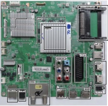
SSB Identification
SSB’s of this chassis are identified by a “715” code on the SSB.
SSB’s of this chassis are identified by a “715” code on the SSB.
715Axxxx-Nnn-MMM-OOOO
• 715 main category, Printed Wiring Board
• Axxxx sub category, sequential coding number
• Nnn Version code
• N Development number
• nn Production number
• MMM Mounting variation code
• OOOO Optional variation code
Make sure when replacing an SSB the SSB identification codes match the replacement panel.
Cable position numbers
In this chassis, the cable position numbers can be defined via the rule that the number is always starting with an “E” followed by the connector number of the current sourcing board. The order is always seen from where the power initiates from. So from PSU to SSB, from SSB to IR/LED panel, from IR/LED panel to keyboard control panel. For example, a cable from the PSU connector CN902 to the SSB connector CN701, will have the position number ECN902.
In this chassis, the cable position numbers can be defined via the rule that the number is always starting with an “E” followed by the connector number of the current sourcing board. The order is always seen from where the power initiates from. So from PSU to SSB, from SSB to IR/LED panel, from IR/LED panel to keyboard control panel. For example, a cable from the PSU connector CN902 to the SSB connector CN701, will have the position number ECN902.