To enter SERVICE MODE, unplug AC cord till lost actual clock time.
Then press and hold Vol (-) button of main unit and remocon key simultaneously.
The both pressing of set key and remote control key will not be possible if clock has been set.
The both pressing of set key and remote control key will not be possible if clock has been set.
To reset clock, either unplug AC cord and allow at least 30
minutes before Power On or alternatively, discharge backup capacitor.
CONFIRMATION OF USING HOURS.
POWER ON total hours and PLAY/REC total hours can be checked on the screen.
Total hours are displayed in 16 system of notation.
NOTE: The confirmation of using hours will not be possible if clock has been set. To reset clock, either unplug AC cord and allow at least 30 minutes before Power On or alternatively, discharge backup capacitor.
Set the VOLUME to minimum.
Press both VOL. DOWN button on the set and the Channel button (6) on the remote control simultaneously.
After the confirmation of using hours, turn off the power.
[(16 x 16 x 16 x thousands digit value) + (16 x 16 x hundreds
digit value) + (16 x tens digit value) + (ones digit value)]
On-Screen Display Adjustment.
Unplug the AC plug for more than 30 minutes to set the clock to the non-setting state. Then, set the volume level to minimum.
Press the VOL. DOWN button on the set and the channel button (9) on the remote control simultaneously to display adjustment mode on the screen.
Unplug the AC plug for more than 30 minutes to set the clock to the non-setting state. Then, set the volume level to minimum.
Press the VOL. DOWN button on the set and the channel button (9) on the remote control simultaneously to display adjustment mode on the screen.
Use the channel buttons (1-8)
on the remote control to select the options.
Press the channel button (0)
on the remote control to end the adjustments.
VCR SECTION PG SHIFTER.
Connect CH-1 on the oscilloscope to TP4001 and CH-2 to TP4501.
Playback the alignment tape. (JG001C)
Press and hold the Tracking-Auto button on the remote control more than 2 seconds to set tracking to center.
Press the VOL. DOWN button on the set and the channel button (3) on the remote control simultaneously until the indicator REC disappears.
If the indicator REC disappears,
adjustment is completed.
(If the above adjustments doesn't work
well go with this procedure.)
Press the VOL. DOWN button on the set and the channel button (3) on the remote control simultaneously until the indicator REC disappears.
When the REC indicator is blinking, press both VOL. DOWN button on the set and the channel button (4) on the remote control simultaneously and adjust the Tracking +/- button until the arising to the down of Head Switching Pulse becomes 6.5 +/-- 0.5H.
Press the Tracking Auto button.
RF AGC DELAY.
Receive the monoscope pattern.
Connect the digital voltmeter between the pin 5 of CP603 and the pin 1 (GND) of CP603.
Connect the digital voltmeter between the pin 5 of CP603 and the pin 1 (GND) of CP603.
Activate the adjustment mode display of and press the channel
button (5) on the remote
control.
The appears on the display.
Press the channel button (1) on the remote control to select "RF AGC DELAY".
Press the VOL. UP/DOWN button on the remote control until the digital voltmeter is 2.50 +/-- 0.05V (80dB).
The appears on the display.
Press the channel button (1) on the remote control to select "RF AGC DELAY".
Press the VOL. UP/DOWN button on the remote control until the digital voltmeter is 2.50 +/-- 0.05V (80dB).
VCO FREERUN.
Connect the oscillator to pin
11 of TU601.
Connect the digital voltmeter to pin 47 of IC601.
Adjust the L608 until the digital voltmeter is 3.6 +/-- 0.05V.
Connect the digital voltmeter to pin 47 of IC601.
Adjust the L608 until the digital voltmeter is 3.6 +/-- 0.05V.
(TV SECTION) CONSTANT VOLTAGE (AC)
Using the remote control, set the brightness and contrast to
normal position.
Connect the digital voltmeter to TP401.
Set condition is AV MODE without signal.
Adjust the VR502 until the DC voltage is DC 130 +/-- 0.5V.
Connect the digital voltmeter to TP401.
Set condition is AV MODE without signal.
Adjust the VR502 until the DC voltage is DC 130 +/-- 0.5V.
CONSTANT VOLTAGE (DC).
Using the remote control, set the brightness and contrast to
normal position.
Connect the digital voltmeter to TP401.
Set condition is AV MODE without signal.
Adjust the VR501 until the DC voltage is DC 130 +/-- 0.5V.
Connect the digital voltmeter to TP401.
Set condition is AV MODE without signal.
Adjust the VR501 until the DC voltage is DC 130 +/-- 0.5V.
CUT OFF.
Place the set with Aging Test for more than 15 minutes.
Set condition is AV MODE without signal.
Using the remote control, set the brightness and contrast to normal position.
Activate the adjustment mode display and press the channel button (5) on the remote control.
The settings appears on the display.
Press the channel button (5) on the remote control to select "CUT OFF".
Adjust the Screen Volume until a dim raster is obtained.
FOCUS.
Receive the monoscope pattern.
Using the remote control, set the brightness and contrast to normal position.
Turn the Focus Volume fully counterclockwise once.
Adjust the Focus Volume until picture is distinct. This adjustment is the same for all CRT TVs, irrespective of it's brand and screen size.
Using the remote control, set the brightness and contrast to normal position.
Turn the Focus Volume fully counterclockwise once.
Adjust the Focus Volume until picture is distinct. This adjustment is the same for all CRT TVs, irrespective of it's brand and screen size.
WHITE BALANCE.
NOTE: Adjust after performing CUT OFF adjustments
before this adjustment.
Place the set with Aging Test for more than 15 minutes.
Receive the white 100% signal from the Pattern Generator.
Using the remote control, set the brightness and contrast
to normal position.
Activate the adjustment mode display and press the channel button (2) on the remote control to select "AKB".
Using the remote control, set the brightness and contrast
to normal position.
Activate the adjustment mode display and press the channel button (2) on the remote control to select "AKB".
Press the channel button (2)
on the remote control to select the "R.BIAS".
Using the SET +/- keys on the remote control, adjust the R.BIAS.
Press the CH. UP/DOWN button on the remote control to select the "G.BIAS", "B.BIAS", "R.DRIVE" or "B.DRIVE".
Using the SET +/- keys on the remote control, adjust the G.BIAS, B.BIAS, R.DRIVE or B.DRIVE.
Perform the above adjustment 7 and 8 until the white color is looked like a white.
SUB BRIGHTNESS.
Receive the monoscope pattern. (RF Input)
Using the remote control, set the brightness and contrast to normal position.
Activate the adjustment mode display and press the channel button (4) on the remote control.
Press the channel button (1) on the remote control to select "BRIGHT".
Press the VOL. UP/DOWN button on the remote control until the white 25% is starting to be visible.
Receive the monoscope pattern. (Audio Video Input).
Press the AV button on the remote control to set to the AV mode. Then perform the above adjustments 2~5.
SUB COLOR.Using the remote control, set the brightness and contrast to normal position.
Activate the adjustment mode display and press the channel button (4) on the remote control.
Press the channel button (1) on the remote control to select "BRIGHT".
Press the VOL. UP/DOWN button on the remote control until the white 25% is starting to be visible.
Receive the monoscope pattern. (Audio Video Input).
Press the AV button on the remote control to set to the AV mode. Then perform the above adjustments 2~5.
Receive the color bar pattern. (RF Input)
Connect the synchro scope to TP801.
Using the remote control, set the brightness, contrast and color to normal position.
Activate the adjustment mode display and press the channel button (4) on the remote control.
Press the channel button (3) on the remote control to select "COLOR".
Adjust the VOLTS RANGE VARIABLE knob of the oscilloscope until the range between white 100% and 0% is set to 4 divisions on the screen of the oscilloscope.
Press the VOL. UP/DOWN button on the remote control until the red level is set to the 4 divisions.
Receive the rainbow pattern. (Audio Video Input)
Press the AV button on the remote control to set to the AV mode. Then perform the above adjustments 2~7.
HORIZONTAL PHASE.
Receive the monoscope pattern.
Using the remote control, set the brightness and contrast to normal position.
Activate the adjustment mode display and press the channel button (1) on the remote control.
Press the channel button (1) on the remote control to select "H. PHASE".
Press the VOL. UP/DOWN button on the remote control until the SHIFT quantity of the OVER SCAN on right and left becomes minimum.
VERTICAL SIZE.
Receive the monoscope pattern.
Using the remote control, set the brightness and contrast to normal position.
Activate the adjustment mode display and press the channel button (1) on the remote control.
Press the channel button (3) on the remote control to select "V. SIZE".
Press the VOL. UP/DOWN button on the remote control until the horizontal over scan is equal to the vertical over scan.
VERTICAL LINEARITY.
Receive
the monoscope pattern.Using the remote control, set the brightness and contrast to normal position.
Activate the adjustment mode display and press the channel button (1) on the remote control.
Press the channel button (5) on the remote control to select "V. LIN".
Press the VOL. UP/DOWN button on the remote control until the SHIFT quantity of the OVER SCAN on upside and downside becomes minimum.
VERTICAL POSITION.
Receive the monoscope pattern.
Using the remote control, set the brightness and contrast to normal position.
Activate the adjustment mode and press the channel button (1) on the remote control.
Press the channel button (4) on the remote control to select "V. POSI".
Press the VOL. UP/DOWN button on the remote control until the horizontal line of the monoscope comes to approximate center of the CRT.
OSD HORIZONTAL.
Receive monoscope pattern.
Using the remote control, set the brightness and contrast to normal position.
Activate the adjustment mode display and press the channel button (5) on the remote control.
Press the channel button (4) on the remote control to select "OSD H".
Press the VOL. UP/DOWN button on the remote control until the difference of A and B becomes minimum.
VERTICAL LINEARITY 60 (AV).
Receive the monoscope pattern (Audio Video Input).
Using the remote control, set the brightness and contrast to normal position.
Activate the adjustment mode display and press the channel button (1) on the remote control.
Press the channel button (5) on the remote control to select "V. LIN".
Press the VOL. UP/DOWN button on the remote control until the horizontal line of the color bar comes to approximate center of the CRT.
Schematic- TV Power [SMPS] – STR-F6707 based.

Schematic – Deflection.

Schematic-chroma LA76812.

SYSCON SCHEMATIC.


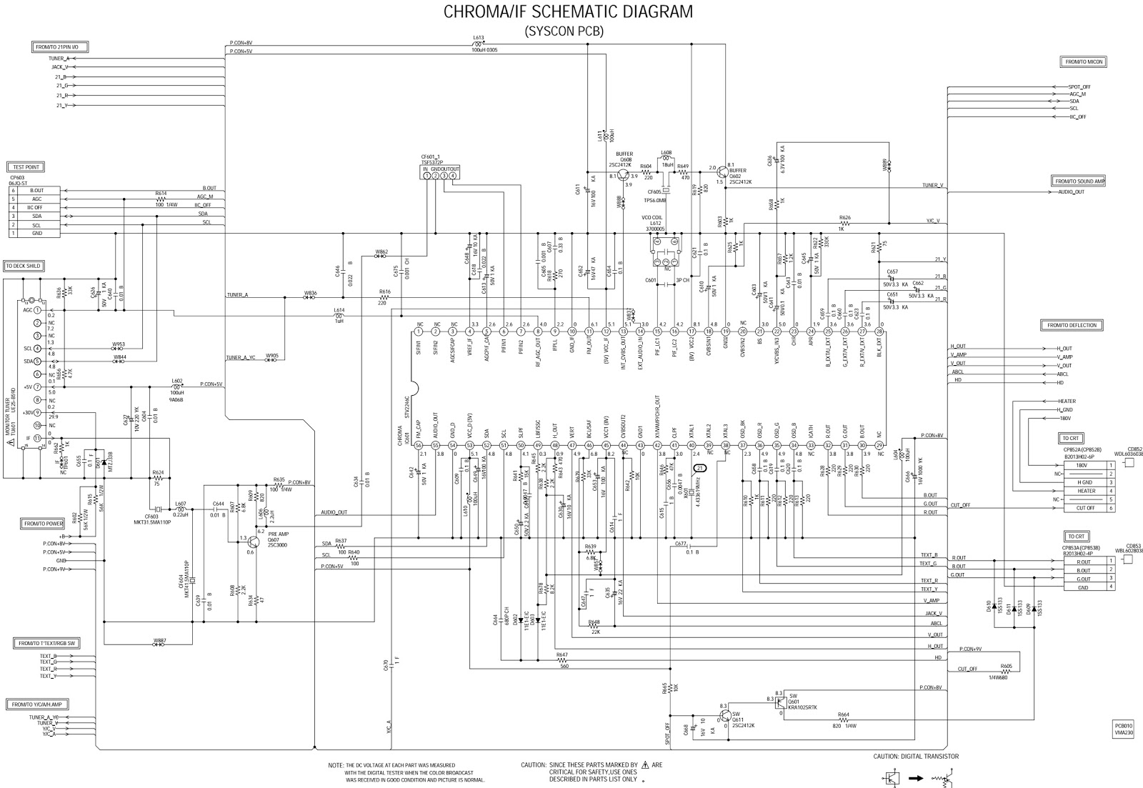
TV power – STRG6653 based.

Interconnection diagram.

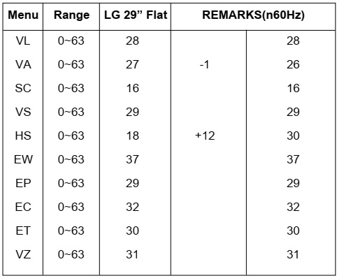
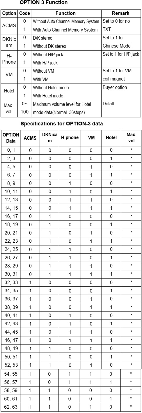
REPLACING THE MEMORY IC.
If a service repair is undertaken where it has been required to change the MEMORY IC, the following steps should be taken to
ensure correct data settings while making reference to TABLE below.
Enter DATA SET mode by setting VOLUME to minimum.If a service repair is undertaken where it has been required to change the MEMORY IC, the following steps should be taken to
ensure correct data settings while making reference to TABLE below.
While holding down VOLUME button on front cabinet, press key 6 on remote
control simultaneously.
ADDRESS and DATA should appear as FIG below.
ADDRESS and DATA should appear as FIG below.
ADDRESS is now selected and should "blink". Using the
SET + or - keys on the remote, step through the
ADDRESS until required ADDRESS to be changed is reached.
Press ENTER to select DATA. When DATA is selected, it will "blink".
Again, step through the DATA using SET + or - until required DATA value has been selected.
Pressing ENTER will take you back to ADDRESS for further selection if necessary.
Repeat steps 3 to 6 until all data has been checked.
When satisfied correct DATA has been entered, turn POWER off (return to STANDBY MODE) to finish DATA input.
The unit will now have the correct DATA for the new MEMORY IC.