REMOVING VIDEO PCB
The video PCB can be removed without moving the rear case. Remove 2 screws, and take out.
Pull out the video PCB unit.
Remove 5 screws from the video PCB unit.
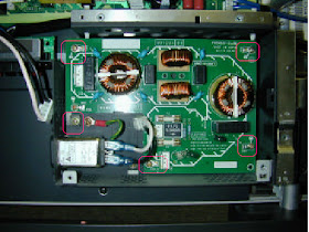
REMOVING THE PFC PCB
- Remove the rear case.
- Remove 2 screws and PFC cover.
Disconnect the marked connectors.
Remove the 5 screws and PFC PCB.
[view after PFC PCB removed]
REMOVING THE MAIN DIGITAL PCB
Remove the video unit.
Remove the DC / DC PCB
Remove the 3 screws and I/O PCB
Remove the marked connectors.
Remove 12 screws and Main Digital Unit.
Remove the shield.
Turn over the Main Digital Board.
Remove the connection PCB
[view after Main Digital PCB removed
Contd:


No comments:
Post a Comment