Sunday, September 30, 2012

PHILIPS DPTV335 DPTV340 DPTV345 SERVICE MODE

PHILIPS – DPTV305 DPTV305F DPTV310 DPTV315 DPTV330 DPTV330F
  PHILIPS 
   DPTV305_DPTV305F_DPTV310_DPTV315_DPTV330_DPTV330F_DPTV335_DPTV340_DPTV345
     ENTERING SERVICE DEFAULT MODE [SDM]
  • To enter Service Default Mode, press the following keys in sequence on the remote control.
  • { 0 > 6 > 2 > 5 > 9 > 6 > Menu}
  • Do not allow the dislay to time out between entries, while keying the sequence.
  • Upon entry into Service Default Mode, the letters [SDM] will be displayed at the upper right corner of the screen.
     Display SDM Screen:
     SPECIAL SDM FUNCTIONS
  • Access to normal user menu:  Pressing the "Menu" button on the remote control switches between the SDM and normal user menus; with SDM mode still active in the background.
  • Run time software identification, and error buffer:  Press the "Status" button on the remote control to toggle the OSD; except SDM; ON and OFF to prevent the OSD from interfering with measurements and scope wave forms. 
  • Access to SAM:  To access Service Alignment Mode in the SDM, simultaneously press the [Volume + & Volume -] buttons on the local keyboard, for at least 4 seconds.
  • Exiting Service Default Mode:  To 'Exit', press "Power" button.
     SERVICE ALIGNMENT MODE {SAM}
  • To enter Service Alignment Mode (SAM), press the following key sequence on the remote control.
  • { 0 > 6 > 2 > 5 > 6 > Status }
  • Do not allow display to time out between entries while keying in the sequence. 
  • It is also possible to enter SAM by pressing the {Volume + & Volume - } key on local keyboard simultaneously for at least 4 seconds.
  • To 'Exit' SAM, press the "Power" button.
     To save the error codes, unplug the AC power cord without turning OFF the set.  When the power is turned back ON, the Service Alignment Mode [SAM] will still be active.
     SAM mode screen
     SAM MENU CONTROL
     Menu items may be selected using the Cursor Up | Dn keys.
  • The selected item will be highlighted.
  • When not all menu items will fit on the screen, pressing the Cursor Up | Dn keys on the remote control will display the Next or Previous menu items.
     With the Cursor Left | Right keys, it is possible to :
  • Activate or Deactivate the selected Menu Item.  
  • Change the value to selected Menu Item.
  • Activate the selected Sub-Menu.
    ACCESS TO NORMAL USER MENU
  • Pressing "Menu" button on the remote cotnrol switches between SAM and the normal user menus; with SAM still active in the background.  Pressing the 'Menu" key in a sub-menu will return the screen to the previous menu.

PHILIPS - DPTV305 DPTV305F DPTV310 DPTV315 DPTV330 DPTV330F DPTV335 DPTV340 DPTV345 _ Dis-assembly

PHILIPSDPTV305_DPTV305F_DPTV310_DPTV315_DPTV330_DPTV330F_DPTV335_DPTV340_DPTV345
DIS-ASSEMBLY PROCEDURES
NOTE: There is no need to the pals tic back back cover to service a PCB or speaker.
Upper Back Cover Removal
  • Remove 12 screws.
  • Remove three screws.
  • Lift cover up to dislodge from pegs, and remove the cover.
Lower Center Back Cover
  1. Remove 3 screws {B}.
  2. Remove 8 screws {C}
Service Position.  Unplug the AC cord from AC mains wall socket.  This service position exposes the entire bottom side of the Power Supply Panel [PSP], Large Signal Panel [LSB], and Small Signal Panel [SSM].  A major portion troubleshooting can be accomplished after completing this procedure.
Remove Lower Back Cover.
  • Remove 12 screws { B & C}
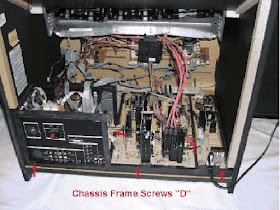
  • Loosen the Chassis Frame.  Remove 5 screws [D] that fasten the Chassis Frame to the Cabinet Bottom.
Service Position Detail -A
Remove Light Barrier.  Service Detail - B
  • Remove 2 screws from the left side - Light Barrier guide, and remove this guide.
  • Gasp the corners of the Chassis Frame and slide in towards out about an inch.  This is required in order that the three metal cleats holding the front edge of the Chassis Frame are released.
  • While holding the back edge of the Chassis Frame down, gasp the panel mounting Bracket and slightly lift the front of the Chassis Frame.
  • Service Detail -C
  • With the rear of the chassis slightly raised, slid the center chassis forward, just far enough that the Rear Jack Panel clears the left side mounting block.  
  • Service position detail - D
  • Now, lift the back edge of the Chassis Frame up while also lifting the front edge to slide forward into the Service Position
  • Service position detail - E
REAR JACK PANEL COVER
Complete all steps to make the Service Position proedure as described above.
  • With the Chassis loose from the cabinet bottom, and the entire chassis re positioned back towards the Cabinet Front, lift the left end of the Chassis Assembly in order to remove the previously hidden screw shown on the following detail.  This screw may be removed by using a 1/4" nut driver or a T20 Torx Driver.  In either case, and extension may be required in order to achieve the proper angle to the head of the screw.
  • Remove 2 screws from the left edge and upper left corner of the Rear Jack Panel Cover.  These two screws may be removed using a 1/4" nut driver.
  • Remove the nut around the 75 Ohm antenna input
  • Remove 10 more screws shown in the following using a Torx 10 Driver.
  • Disconnect 2 connectors from the top of the rear switch panel.  This panel fastens to the jack panel cover and may easily be removed or re connected once the jack panel cover is completely free of the chassis assembly.
  • Although all screws should now have be removed, care must be taken on core models featuring the HD input.  The jack panel cover has a plastic hook that clips into a hole on the the DVI panel.  Gently lift this hook while removing the jack panel.

PHILIPS PTV305 DPTV305F DPTV310 DPTV315 DPTV330 DPTV330F DPTV335 DPTV340 DPTV345 POWER SUPPLY SCHEMAIC

PHILIPS PTV305_DPTV305F_DPTV310_DPTV315_DPTV330_DPTV330F_DPTV335_DPTV340_DPTV345
STANDBY POWER SUPPLY SCHEMATIC
POWER SUPPLY [FULL] SCHEMATIC
     See the images Enlarged by Google picasa-3.  Copy and paste images to 'My documents > My pictures folder'.  You can retrieve them to Picasa-3, after installing Google Picasa-3 picture viewer  to your system.  It is a free download from Google.
POWER FAIL SHUTDOWN SECTION SCHEMATIC

How to enter Service Mode - PHILIPS 37MF437B/37 42MF437B/37 47MF437B/37 42PFL437B/37 47PFL437B/37

SERVICE MODE [FACTORY MODE]
  • Press "Menu" in normal operation mode to enter OSD.
  • Press [0 > 6 > 2 > 5 > 9 > 6 > Menu] by the remote control in OSD.
  • Press "Menu" again.  The screen will appear "FAC" in top right corner.
  • OSD behavior:
  • Before press number key change OSD item.
  • Now remove previous function, press number key then press "OK" will change value.
  • To exit service mode [Factory Mode]; press '0' key and the press"OK".

PHILIPS Dali 32PFL3605D 40PFL3605D LED BLINKING CODES

     Errors can also be displayed by the Blinking LED procedure.  The method is to repeatedly  let the front LED pulse with as many pulses as the error code number, followed by a period of 1.5 seconds in which the LED is Off.  The the sequence repeats:
     For example, error code '4' will result in four times in sequence LED 'on' for 0.25 seconds / LED 'off' for 0.25 seconds.   Any remote control command terminates the sequence.  Error code LED blinking is in red color.
     Example: The content of the error buffer is "12 9 6 0 0"  After entering SDM, the following occurs [Method to enter SDM has been described in the previous post].
  • 1 long blink of 5 seconds to start up the sequence.
  • 12 short blinks followed by a pause of 1.5 seconds,
  • 9 short blinks followed by a pause of 1.5 seconds, 
  • 6 short blinks followd by a pause of 1.5 seconds,
  • 1 long blink of 1.5 seconds to finish the sequence, 
  • The sequence starts again with 12 short blinks.
DISPLAYING THE ENTIRE ERROR BUFFER
The entire buffer is displayed when Service Mode "SDM" is entered.  In case the TV set is in protection or standby: The blinking LED procedure sequence; as in SDM mode in normal operation; must be triggered by the following Remote command sequence:
" Mute => '062500' => OK"
In order to avoid confusion with remote control signal reception blinking, this blinking procedure is terminated when a remote control command is received.
ERROR CODES AND DEFECTIVE PART [BOARD]

Layer-1 error code
Defective board
Layer-2 error code
Defective board

2
SSB
11
Speaker DC protection active on SSB
4
IPB
12
+12 missing | low, IPB defective, Power_Down.
4
IPB
13
POK line defective
2
SSB
15
EEPROM I2C error on SSB, M24C16.
2
SSB
16
Tuner I2C error on SSB.
2
SSB
18
IF demodulator I2C error on SSB, TDA9886.
The 'Layer-1' codes are pointing to the defective board.  They are triggered by LED blinking when CSM is activated.  In LC 10- platform , only two boards are present:  The SSB & PSU | IPB, meaning only the following layer-1 errors are defined.
2: SSB
4: PSU | IPB.
HOW TO READ ERROR BUFFER
  • On screen via the SAM | SDM | CSM
  • ERROR: 0 0 0 0 0 ; No errors detected.
  • ERROR: 6 0 0 0  0; Error code '6' is the last and only error detected.
  • ERROR: 9 6 0 0 0; Error code '6' was detected first & error code '9' is detected; newest; error. 
The last found error is displayed on the left.  An error with a designated error code may never lead to a deadlock situation.  This means that it must be always be diagnosable. 

Saturday, September 29, 2012

PHILIPS Dali - 32PFL3605D 40PFL3605D SERVICE MODE


PHILIPS Dali -  32PFL3605D
ENTER SERVICE MODE
The service mode feature to these sets are spit into 4 parts
  1. Service Default Mode [SDM]
  2. Service Alignment Mode [SAM]
  3. Customer Service Mode [CAM]
  4. Computer Aided Repair [ComPair]
SDM & SAM offer features, which can be used by the service technician to repair | align the set.  Some feature are:
  • A pre-defined situation to ensure measurements can be made under uniform conditions.[SDM]
  • Activates the blinking LED procedure for error identification when no picture is available. [SDM]
  • The possibility to overrule software protections when SDM is entered  via the service pins.
  • Make alignments, such as White Tone, De-select options, enter option codes, reset the error buffer [SAM]
  • display information; SDM or SAM indication in upper right corner of the screen, error buffer, software version, operating hours, options and option codes, sub menus etc:
SERVICE DEFAULT MODE [SDM]
  • To activate SDM, use one of the following methods.
  • Press the following key sequence on the remote control [0 > 6 > 2 > 5 > 9 > 6 ] followed by Menu] button (or)
  • Short one of the service pads on the TV board during cold start.  Then press the mains button; remove the short after start up.
  • Caution:  When doing this the technician must know exactly what he is doing, as it could damage the TV set.
Service Pads [SSB component side]
ON SCREEN MENU
Menu items and explanations
  • xxxxx: Operating Hours in Decimal.
  • AAAAAB-XX.YY: Software identification.
  • ERR:  Shows all errors detected since the last time the buffer was erased in format <xxx> <xxx> <xxx> <xxx> (five errors possible).
  • OP:  Used to read-out the option bytes.  Ten codes (in two rows) are possible.
TO NAVIGATE
In the SAM menu, select menu items with UP | DN keys on the remote control.  The selected item will be indicated.  When all menu items not fits on the screen, use Up | Dn keys to display next | previous menu items.
With Left | Right keys, it is possible to 
- Activate selected menu item.
- Change the data value to selected item.
- Activate the selected Sub-Menu.
When Menu button is pressed twice while in top level SAM, the set will switch to normal user menu; with SAM mode still active in the background.  To return to SAM menu press 'Menu' button.
The "[i] INFO" key from user remote control will toggle the OSD On | Off with SAM OSD remains always ON.
Press [0 > 6 > 2 > 5 > 9 > 6] directly followed by "Menu" button to switch to SDM; do not allow the display to time out between entries while keying the sequence.
To "EXIT" switch the SET to Standby by pressing the mains button on the remote control or the TV set.

How to update the Firmware - PHILIPS 26MF605W/17 FIRMWARE UPDATE

Firmware update procedure
"Easywriter".  The software is provided by Novatek to upgrade the firmware of CPU.  It is a Windows based program, which cannot be run in MS-DOS.  DDC2BI_ISP TOOL (3138 106 10396) is for the interface between 'Parallel Port of PC' and '15 pin D-Sub connector of monitor.
Make a folder on PC.  Copy ISP software EasyWriter into that folder.
Copy the 'FL1_NAFTA_26_V120_3A10.hex' to C:\26MF605W-17.
FIRMWARE UPDATE
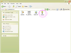
  1. Double click the Easywriter.exe icon in desktop, then appears;
2. Press the Load hex, then select FL1_NAFTA_20_V120_3A10
3. Press the AUTO run program, the firmware be updated.

4. Press 'File' =. Exit to end program.
If there is a warning message coming as shown below, Check the AC  Adapter, Video Cable or Novatek MCU.

PHILIPS 26MF605W/17 32MF605W/17 Re-Programming digital DDC IC Service Help.

                                                   [3]
All connection settings are described as previous post.
READ DDC DATA FROM MONITOR.
  • Click 'Tools' icon from the toolbar to bring up the Channels 'configuration setup'
Select the DDC2Bi as communication channel.
Click 'OK' button to confirm selection.
Click 'Read EDID function' to read DDC EDID data from monitor.  The EDID codes will display on screen.
Click 'New' function icon from the tool bar, bring up step 1 of 9
EDID46DDC application provides the function selection and text change; select & fill out; from step1 to step 9.
Step-4:  Modify DDC data:
  1. Click next
  2. Click next
  3. Click next
See screen shots:
4. Click next
5. Click next
See screen shots
Click next.  
In this step confirm the Descriptor Data Type is Monitor Range Limits, and all the items are same as below.
Click next.
Click 'Finish' to Exit setup.  Serial number can be filled up at this moment.  For example [26MF605002].
Must modify the Serial number in step 9, otherwise the serial number in OSD couldn't be modified correctly.
Step-5:  Write DDC Data.
Configuration should be like this. 
Press "OK".
Access Factory mode [Refer previous post for details]
Push 'Menu' to Exit OSD menu.
Click [Write EDID] icon from the tool bar to write DDC data.  Wait for 20 to 30 seconds.  DDC data will be finished Writing.
To save DDC data: Click Save as. [If you want to save]
Pull down the File Menu, and press 'Exit'.
Turn OFF the monitor, Exit Factory Mode.

PHILIPS 26MF605W/17 - WRITE DDC DATA_DDC INSTRUCTIONS _ Service Help.


[2]

The configurations should be same as described in the previous post.

Configuration setup

  • Access Factory Mode.
  • Press 'Power' button.  Then quickly press 'Volume - and Volume + and hold these two buttons.  The screen comes out 'Waiting for automatic Adjustments", then the screen will be black for one second, until comes out "Windows Screen" => then release these tow buttons, then press 'Menu" button, wait until the OSD menu with characters "F1/FL1 NAFTA V0 91.1041124 ADJUST"
  • Push to exit OSD.
  • Click 'write EDID' icon from the toolbar to write DDC data.  Then the screen will be black for 2-3 seconds, then the screen recovers, and 'ATTENTION NO VIDEO INPUT' will come on the screen of the monitor, wait for 20-30 seconds, DDC data will be finished writing.
Save DDC Data.

Sometimes you may need to save DDC data as a text file for using  in other IC chip.  To save DDC data, follow the steps below.
  • Click 'Save' button or [click file -> save as] from the tool bar and give a file name .  Type the file type is EDID46 file(*.ddc) which can be open in WordPad, the texts of DDC data & table [128 bytes, hex code] can be modified.  if DDC TEXTS & HEX Table are completely correct, it can be saved as .ddc file to re-load into DDC IC for DDC Data application.


  • Click 'save'.
EXIT DDC program
  • Pull down the file menu, and select 'Exit'.

Turn OFF the Monitor, Exit the factory Mode.

Re-programming DDC IC follows by next post.

PHILIPS 26MF605W/17 DDC INSTRUCTIONS


     There is no hardware IC [DDC IC] any more.  Main EEPROM stores all factory settings and DDC data (EDID code) which is also called Software DDC.  The main EEPROM can be re-programmed by enabling 'factory memory data write' function on the DDC program EDID46.EXE.
     In order to avoid that monitor entering power saving mode due to sync which cut off by alignment box, it is necessary to initialize alignment box before running programming software EDID46.EXE.
  • Supply 8 ~ 12 Vdc power source to the alignment box, by plugging a DC power cord.
  • Connect the printer D-Sub cable for the monitor.  
INSTALLATION 
Start MS Windows.
  • The program 'EDID46.EXE' in service manual CD ROM be copied to C:\
  • Click 'Start', choose 'Run' at start menu as windows.
  • At the sub-menu, type the letter of the hard disc drive followed by :EDID46 {For example, C:\EDID46}
  • Click "OK" button.  The Main Menu appears.  This is for initialize alignment box.
  • Click this icon  from the toolbar to bring up the channels 'configuration setup'
  • Select DDC2Bi as the communication channel.
  • Click 'OK' button to confirm.
  • Click "Read EDID function icon" to read DDC EDID data from monitor.  The EDID codes will display on the screen.
  • Click [New Function] icon from the tool bar, bring step 1 of 9 
  • EDID46 DDC application provides the function selection.
  • Click next. bring up Fig.15
  • Click next.  Bring up 16.
  • Click next. Bring 17
  • Click next.  Bring 18
  • Click next.  Bring 19.
  • Click next.  Bring 20.  In this step, confirm the Descriptor Data Type is Monitor Range Limits, and all items are same below.
  • Click next.  Bring 21
  • Click next.  Bring up-22. Click 'Finish' to exit the Setup Window.
  • Must modify the the Serial Number, in Step-9, otherwise the serial number in OSD couldn't be modified correctly.
[Write DDC Data: followed by next post]