Sunday, August 31, 2014

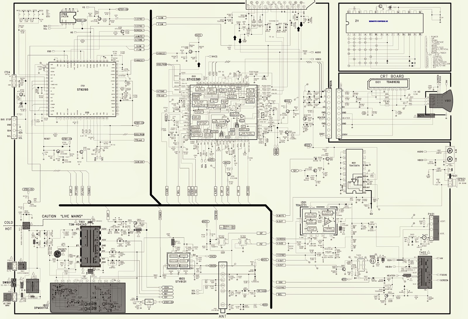
HOW TO ENTER SERVICE MODE_ONIDA 21_29 OXYGEN THUNDER CTV – MAIN and VIDEO OUTPUT SCHEMATIC

SERVICE MODE
* Enter into the service mode by pressing VSM + Display buttons on the remote control.
** If any changes are done in the settings, the set should be switched off by mains ON/OFF & switched ON again.
MAIN CIRCUIT_HORIZONTAL-VERTICAL SCAN OUT
VIDEO OUTPUT (CRT BASE CARD)_SCHEMATIC
CLICK ON THE SCHEMATICS TO ZOOM IN

ONIDA 21_29 OXYGEN THUNDER CTV SMPS SCHEMATICS (Circuit Diagrams)

This set has two SMPS sections.  One for its main circuit and the other for the Sub-woofer circuit.
MAIN POWER_SMPS SCHEMATIC
SUB-WOOFER POWER [SMPS]
CLICK ON THE SCHEMATICS TO MAGNIFY

HOW TO ENTER SERVICE MODE - JVC AV-21JT5EU / AV-21JT5EBU / AV-14JT5EU / AV-14JT5EBU

JVC AV-21JT5EU / AV-21JT5EBU / AV-14JT5EU / AV-14JT5EBU
ICs USED: 24LC16_TDA6103Q_STV2238D_ST92195_TDA1771_STV8131_DPM001T1A
SERVICE MODE
HOW TO ENTER AND EXIT FROM SERVICE MODE
* Press the “Muting” and “recall” key of the remote control at the same time to display the service menu screen. [NB: You should have its original remote control to enter the service mode.  No universal remote control can be used for this purpose]
* To exit from service mode, turn off the power switch.
SERVICE MODE ADJUSTMENTS
* Select the setting item you want to change with “P▲/▼” key on the remote control unit.  The item you have selected will be indicated by yellow on the display.
* To change the set values, use ◄/► key on the remote control.  When setting is completed, turn off the power.  The changed values are stored in the memory.
Service mode screen
SCHEMATIC - FULL
CLICK ON THE PICTURES TO ZOOM IN

LG 21FU3RL 21FU3RL-T3 – SCHEMATIC (Circuit Diagram) - 21" CTV

ICs used: (LV762xx - Chroma)_LC75024E_W6553A (W6554A)-Power Switching_LA72730_STV9326_TDA8145_LA72702_(LA42101/LA4202L/LA42102N –Audio Output)
Receiving System.
PAL BG,DK,I / NTSC M(AV3.58/4.43) > China/ Indonesia/ Thai/ Vietnam.
PAL BG,DK,I / NTSC M(AV3.58/4.43), SECAM DK > CIS
PAL BG,DK,I / NTSC M(AV3.58/4.43), SECAM BG,DK,L > Asia/ Middle East/ Africa.
SCHEMATIC [CLICK ON THE SCHEMATIC TO ZOOM IN]

Saturday, August 30, 2014

SAMSUNG LCD TV LE22B35*** - TROUBLESHOOTING - NORMAL AUDIO - NO PICTURE

No Video (Analogue PC signal) / No Video (HDMI - Digital Signal)
NO VIDEO_ANALOGUE PC SIGNAL
* Audio is normal but no picture is displayed on the screen.
> Check the PC source
> Check the Arsenal, SEMS12
> This may happen when the LVDS cable connecting the Main Board and the Panel is disconnected.
NO VIDEO_HDMI DIGITAL SIGNAL
* Audio is normal but no picture is displayed on the screen.
> Check the HDMI source.
> Check the HDMI switch, Check the SEMS12
> This may happen when the LVDS cable connecting the Main Board and the Panel is disconnected.

SAMSUNG LE22B35*** LCD TV NO POWER TROUBLESHOOTING

NO POWER TROUBLESHOOTING
* The LEDs on the front panel do not work when connecting the power cord.
* The SMPS relay does not work when connecting the power cord.
* The unit appears to be dead.
> The IP relay or the LEDs on the front panel does not work when connecting the power cord if the cables are improperly connected or the Main Board or SMPS is not functioning. In this case, check the following:
> Check the internal cable connection status inside the unit.
> Check the fuses of each part. - Check the output voltage of SMPS. - Replace the Main Board.

Friday, August 29, 2014

HOW TO DISASSEMBLE - SAMSUNG LE22B35*** LCD TVs [Chassis: N65D]

DISASSEMBLE PROCEDURE
Disconnect the LCD TV from the power source before disassembly.  Never use metal instruments to pry apart the cabinet.
* Place the TV face down on cushioned tale. Remove 3 screws from the back cabinet.
* Lift up the Stand.
* Remove the 4Screws of main board and 7 Screws of IP Board And remove Speaker and Harness.
Lift up the panel.
Reassembly procedures are in the reverse order of disassembly procedures.

SAMSUNG LCD-TV LE22B35*** SERVICE MODE – FACOTRY MODE - FACTORY DATA.

TO ENTER FACTORY MODE
* To enter ‘Service Mode’ Press the remote -control keys in this sequence:
* If you do not have Factory remote – control [Power OFF > INFO > MENU > MUTE > POWER ON]
HOW TO ACCESS SERVICE MODE
Using the Customer Remote
  1. Turn the power off and set to stand-by mode
  2. Press the remote buttons in this order; POWER OFF - INFO - MUTE - POWER ON to turn the set on.
  3. The set turns on and enters service mode. This may take approximately 20 seconds.
  4. Press the Power button to exit and store data in memory.
If you fail to enter service mode, repeat steps 1 and 2 above.
Initial SERVICE MODE DISPLAY State
HOW TO ENTER HIDDEN FACTORY MODE
# into the factory mode
# move the tap to Advanced
# key input : 0 + 0 + 0 + 0
** hidden menu : Advanced.
BUTTONS OPERATION WITHIN THE SERVICE MODE
* Direction Keys ▲/▼ à Item Selection by Moving the Cursor.
* Direction Keys ◄/► à Data Increase / Decrease for the Selected Item.
* Source à Cycles through the active input source that is connected to the unit.
FACTORY DATA
CLICK ON THE TABLE TO MAGNIFY

Thursday, August 28, 2014

HOW TO remove the MD mechanism & CAUTIONS WHEN ASSEMBLY - AIWA XR HG5MD - MD / CD STEREO SYSTEM.


REMOVAL OF THE MD MECHANISM & CAUTIONS WHEN ASSEMBLEY
BASIC TAPE MECHANISM : 2ZM-3MK2 PR4NM
BASIC CD MECHANISM : AZG-1 ZD8RMDM
BASIC MD MECHANISM : AZG-7 DM
1. Remove the four screws (BVT2+3-10 W/O SLOT) of A.  Remove AZG-4 in the direction of the arrow.
2. Remove the four screws (VTT+3-4) of B.  Set the mechanism in the PLAY state.  Remove the HLDR, SHIELD TOP in the direction of the arrow.
3. Remove the two screws (S-SCREW, MD TF) of C.  Remove the two screws (S-SCREW MD T) of D.  Remove the four FFCs and remove the MD MECHANISM.
4. Remove the screw (VW+1.7-5) of A.  Remove the HEAD, OWH.  Remove the two screws (VTT+2-3) of B.  Remove the PLATE ASSY, SLIDE L and the PLATE, SLIDE R. in the direction of the arrow.
5. Move the ZZG-D in the direction of arrow (a). While pushing the BOSS in the direction of arrow (b), remove it in the direction of arrow (c).
6. Remove the CAM, LOAD in the direction of the arrow.
CAUTIONS WHEN ASSEMBLY
1. Assembling the CAM, LOAD
Move the LEVER ASSY, CAM in the direction of the arrow as far as it can go.  Rotate the CAM, LOAD so that its positioning hole is moved as close as possible to the shaft of the LEVER, SW H.  Attach the CAM, LOAD so that it engages with the teeth of the GEAR, IDLER2.
2. Assembling the PLATE ASSY, SLIDE L
Align the shaft of the PLATE ASSY, SLIDE L with the arrow-marked position of the CAM, LOAD.
CLICK ON THE PICTURES TO MAGNIFY

AIWA XR HG5MD - MD CD STEREO SYSTEM _ CIRCUIT DIAGRAM

SCHEMATIC DIAGRAMS [Click on the Schematics to Magnify]
POWER
FRONT BOARD
TUNER SECTION
MAIN

CTV CIRCUIT DIAGRAM- USING LA76931 IC

CIRCUIT DIAGRAM_FULL [CLICK ON THE SCHEMATIC TO MAGNIFY]

SONY HCD-EX660Z/EX880Z/EX990Z - CIRCUIT DIAGRAM

Used ICs_ STR-Y6763_MM1431_SSC6700_BA4558F_BD00G0WEFJ-SE2_SL-8008TM-TLS_BA17807FP-E2_KIA7809AF_PST8229UL_SSC6700_TAS5611APHDR(Power Amp)
AMP SMPS BOARD
AMP SMPS PWB
POWER AMP MODULE SCHEMATIC
CLICK ON THE SCHEMATICS TO ZOOM IN

HOW TO ENTER SERVICE MODE TO TCL L24D10 MT23-AP LCD TV

SERVICE MODE [FACTORY MODE]
Method-1
In any sources, enter to the menu, move cursor to Contrast item, and then press 9,7,3,5 keys continuously on the remote control.
The factory menu will appear as shown below.
Method-2
In the “Production” of the factory menu, if set “FacMode” and “FacHotkey” as “ON”.
There will be a “P” on the left corner of the panel.  
In this status, you can enter the factory menu by pressing the “Return” key of the remote control.
Note:  In the factory menu, you can return to the previous menu by the “Menu” key of remote control.
To exit the factory mode.
Press the “Exit” key on the remote control.
Press the “Menu” key of remote control to go back to the previous menu.  If the hotkey of factory menu is “ON”, the status cannot be changed by turn off the TV. You need to change the hotkey of the factory to “OFF”
SHOP INT should be done at the last alignment if NVM is set “OK”, you do not need to do this.

Wednesday, August 27, 2014

LG50PQ30 plasma TV POWER SUPPLY BOARD [SMPS] CHECKING PROCEDURE

POWER SUPPLY BOARD [SMPS] OPERATION PRINCIPLE_VOLTAGES_Va & Vs Adjustments.
OPERATION PRINCPLE
  AC Voltage is supplied to the SMPS Board at Connector SC101 from the AC Input assembly. Standby 5V is developed from 160V source supply (which during run measures 380V measured from the primary fuse F302). This supply is also used to generate all other voltages on the SMPS.  The STBY5V (standby) is B+ for the Controller (IC701) on the SMPS and output at P813 pins 11 and 23 then sent to the Main board for Microprocessor (IC1) operation. AC Detect is generated on the SMPS, by rectifying a small sample of the A/C Line at D102 and associated circuitry and routed to the Controller (IC701) where it outputs at pin 15 and sent to P813 pin 18 to the Main Board where it is sensed and monitored by the Main Microprocessor (IC1). The AC Det in this set works differently than most. If AC Det is missing the Microprocessor will turn off the television in about 10 seconds after turn on.
This will happen each time turn on is attempted.
  A new feature included on the side keypad is called a Main Power Switch which opens a ground allowing the “Key On” line of P813 Pin 24 to go high, turning off the 5V STB line defeating the Micro Processor (IC1) on the Main Board and Remote Control Operation. When the Microprocessor (IC1) on the Main board receives an “ON“ Command from either the Power button or the Remote IR Signal, it outputs a high called RL ON at Pin 19 of P813. This command causes the Relay-Drive Circuit to close both Relays RL102 and RL103 bringing the PFC source up to full power by increasing the 160V standby to 380V run which can be read measuring voltage at Fuse F302 and F801 from “Hot” Ground. At this time the run voltages 12V, and +5V sources become active and are sent to the Main Board via P813 (12V at pins 5 and 6 and 5V at pins 9,10, and 12). The 5V detect line from the SMPS Board to the Main Board can be measured at pin 17 of P813. It is not used. 
  The next step is for the Microprocessor (IC1) on the Main Board to output a high on M5V ON Line to the SMPS at P813 Pin 21 which is sensed by the Controller (IC701) turning on the M5V line and output at P811 pins 9 and 10 to the Y-SUS board P201 pins 9, 10. Then it Is routed to the Control and Z-SUS boards.  Full Power occurs when the Microprocessor (IC1) on the Main Board brings the VS-ON line high at Pin 20 of P813 of the SMPS Board. VS-ON is routed to the Controller (IC701) which turns on the 17V Audio, VA, and the VS supplies. VA and VS output at P811 to the Y-SUS board. (VA pins 6 and 7 and VS pins 1 and 2). The 17V Audio supply outputs to the Main board at P814 pins 1 and 2 and used for Audio processing and amplification.  
  AUTO GND Pin 22 of P813: This pin is grounded on the Main board. When it is grounded, the Controller IC701 works in the normal mode, meaning it turns on the power supply via commands sent from the Main board. When this pin is floated (opened), it pulls up and turns the Controller IC701 on in the Auto mode. In this state, the Controller turns on the power supply in stages automatically. A load is necessary to perform a good test of the SMPS if the Main board is suspect.
Va & Vs adjustments
These adjustments are a must; when power board [SMPS] or Display panel are replaced.  Details about these voltages will be marked on each panel, and will differ to each other.
HOW TO TEST THE POWER SUPPLY [SMPS]
Using two 100 Watt light bulbs (Filament Type Only), attach one end to Vs and the other end to ground. Apply AC toSC101. If the light bulbs turn on and VS is the correct voltage, allow the SMPS to run for several minutes to be sure it will operate under load. If this test is successful land all other voltages are generated, you can be fairly assured the power supply is OK.
Note: To be 100% sure, you would need to read the current handling capabilities of each power supply listed on the silk screen on the SMPS and place each supply voltage under the appropriate load.
Note: This SMPS will run without a load, however if the Vs is not loaded, the 17V may pulsate up and down.  It is always best to test the SMPS under a load using the 2 light bulbs.
POWER SUPPLY STATIC TEST
CONNECTOR P813 VOLTAGES & DIODE CHECK DATA
P813 CONNECTOR “SMPS" to “Main" P1006.
Note: The 17V turns on when the VS On command arrives.
Note: The 5V/12V turns on when the RL On command arrives.
Note: If the Key On line is 4.39V, the Main Power Switch is open.  Stand-By 5V will shut off.
Connector SC101 and P811 Identification, Voltages and Diode Check.