Friday, August 30, 2013

HOW TO DISASSEMBLE DELL 1907FPc_LCD MONITOR

DISASSEMBLE PROCEDURE
  • Rotate the stand to allow access to the stand release button.
  • Press the Stand release button and lift up the Stand and away from the monitor.
  • Remove the 4 screws.
  • Pry the monitor up then find out the hooks’ position, use the tool (like the picture or other card) to insert into the gap of bezel and rear cover.

  • Take off the bezel.
  • Turn over the monitor as the Fig, hold the rear cover, and then slightly remove it.
  • Remove the 4 screws.

  • Remove the USB2 board cover.
  • Remove the 5 screws.
  • Disconnect the wire harness between USB1 and USB2.

  • Push the main shield as the arrowhead direction.
  • Disconnect the connector pin: Disconnect the connector pin between key and main boards.

DELL 19" LCD MONITOR_1907FPc - POWER AND INVERTER SCHEMATIC _ STP10NK70ZFP (Power Switching) – LD7552 IC (Power Control) – PC123FY2 4P (Opto-isolator)

POWER [SMPS] SCHEMATIC
INVERTER
CLICK ON PICTURES TO ZOOM

CB20 _ CB21H1T5X_SAMSUNG CRT TV - POWER_CRT_VERTICAL_HORIZONTAL SECTION - SCHEMATIC (Circuit Diagram) [KA7630 – TDA8356 – TDA61070 – KSC5386 – KA3S0680AF(Power Control)]


SCHEMATIC DIAGRAM

Click on Schematic to Zoom

Thursday, August 29, 2013

SONY BDP BX18 – S185 – S186 - BLU-RAY DISC PLAYER - SERVICE MODE - Optical device replacement - How to Remove Disc at No Power -

DISC REMOVAL PROCEDURE (FORCED EJECTION)
  • Remove the upper case.
  • Insert a clip in the hole of a drive and open a tray.
OPTICAL DEVICE REPLACEMENT
  • Install it in PC after downloading two set of software.
  • Microsoft .NET Framework Version 2.0 Redistributable Package (x86)
  • Microsoft .NET Framework 2.0 Service Pack 1 (x86)
  • Take a photograph of the bar code on the optical device. The valid bar code photo as shown.
  • Drag-and-drop the bar code photograph to the icon of decode software (BDPRdec).
The decode software is a complete set of “BDPRdec”,  “T asman.Bars.dll”, and “SavePath”.
Because decode software cannot be attached, it separately distributes it.
  • Input the password when you start decodes software.
Inquire of each service headquarters because the password cannot be disclosed.
  • Write the decode data to the set.
BEFORE BU REPLACEMNT
{CLICK ON PICTURES TO ZOOM}
BDP 6.9G (B D P-S1 8 5 ) series component structures as sambas conventional DVD Players.  However player requires precise read out functions and also secures contents Protection system.
Since above requirement, it is necessary to set/adjust BU data to EEPROM.
Replace BU(MB is original)
Replace MB (BU is original)
Replace both BU and MB
Requirement
  • Digital camera (recommend with macro mode)
  • Barcode decoder (BDPRdec_ver2.0) installed in JIG PC’s
  • USB memory
  • ESD work bench.
The servo adjustment procedure will be carried out during OP data Writing.  There is no manual adjustment procedure. LD ON TIME history doesn't carry over.
Do not touch any optical block parts, Turn Table and during replacing. BD Laser diode is very sensitive.
BU ADJUSTMENT FLOW
BU Data Decode Jig
JIG Name: BDPRdec. Exe
Release: 2010.11.26
Version : 2.0.0.0
Software Contents:
BDPRdec.exe ; Software
SavePath.ini ; decoded file destination setting file (initial destination is C:¥BuData.txt)
Tasman.Bars.dll ;decode dll
Uninst.exe ; unistall BDPRd ec.exe from PC
Installations
Unzip files to any PC Folder
Check the attached 2D code photo(OK_sample.JPG) drag-and-drop onto BDPRdec.exe, the Password will be required at first time only, no need P/W from second time.
If there is the error message (.NETframe work requirements) please apply Microsoft .NET Framework 2.0 (or 2.0 SP1) from Microsoft download site.

AUDIO OUTPUT SCHEMATIC DIAGRAM - TDA7495 - [Stereo] - AUDIOVOX FPE3000


SCHEMATIC DIAGRAM

CLICK ON SCHEMATIC TO ZOOM

EPSON STYLUS PHOTO - R280 - R285 - R290 - HOW TO ADJUST PG

PG ADJUST
Adjust the distance between the head surface and the Paper Guide Front Assy (platen) properly and adjust the parallelism on the 0th column side and on the 80th columns side to ensure reliable print quality.  Once the Carriage Assy and/or Adjustment Bushes have been removed or whenever necessary for any other reason, make this adjustment to correct the deviation of the platen gap.
Tools to be used
  • Thickness gauge:  1.15 mm (x2) 1.3 mm (x2)
  • Phillips screwdriver.
  1. The thickness gauge to be used must be free from dust and dirt and from deformation. Be sure to clean it before use.  ! Take care that the Print Head is not soiled or scratched.  To ensure high accuracy of adjustment, install new ink cartridges in the carriage, and move the carriage right and left by pulling the belt without holding the carriage.
  2. Make this adjustment after installing the mechanism unit in the Housing Lower. (Install the Linear Scale after adjustment.)
  3. With EPSON Stylus Photo R280/R285/R290, four stages of PG setting are available by means of the APG Mechanism. However, make this adjustment with the mechanism in the minimum PG position (PG-: 1.2 mm).
PG POSITIONS
PG POSITION AT PG ADJUSTMENT
CLICK ON PICTURES TO ZOOM

Adjustment procedure (Specified PG value: 1.2 ± 0.1 mm)
  • Install new ink cartridges in the carriage.
  • Remove the Cable Holder Frame.
  • Check that the APG Assy and the carriage are in the PG-position.
  • Move the carriage to the centre of the platen, and place 1.15 mm thickness gauge on the left aligning its left edge with the second rib of the Front Paper Guide. And place another 1.15 mm thickness gauge on the right aligning its right edge with the rightmost rib of the Front Paper Guide.
NOTE: The thickness gauge must not be set over the leftmost rib on the Front Paper Guide.
  • Pull the Timing Belt to move the carriage to the left end.
  • If the carriage comes in contact with the gauge, adjust the Left Parallelism Bush to raise the carriage to a position where the Print head does not come in contact with gauge.
  • Pull the Timing Belt to move the carriage to the right end.
  • If the carriage comes in contact with the gauge, adjust the Right Parallelism Bush to raise the carriage to a position where the Print head does not come in contact with gauge.
  • Move the carriage to the middle area of the platen, and place 1.3 mm thickness gauges at the left and right ends of the platen.
  • Pull the Timing Belt to move the carriage to the left end.
  • If the carriage does not come in contact with the gauge, make the adjustment again.
  • Pull the Timing Belt to move the carriage to the right end.
  • If the carriage does not come in contact with the gauge, make the adjustment again.
  • Mark the indicated graduation position of the right and left Parallelism Bush, and tighten the screws.(Screw tightening torque: 0.8±0.1 N•m)
PG ADJUSTMENT-1
PG ADJUSTMENT-2

Wednesday, August 28, 2013

POWER SUPPLY [SMPS] SCHEMATIC [Circuit Diagram] - USING 2SK3326 (Power Switching) – LTV 817M-VB (Opto-coupler Isolator) - TOSHIBA 20A45C


SMPS SCHEMATIC
Click on schematic to Zoom

HOW TO DISASSEMBLE SHARP AM 400 - SHARP AM 300DE - LASER SCANNER COPIER PRINTER


DISASSEMBLE PROCEDURE
Easy and simple disassembly/assembly procedures of some parts and units are omitted. refer to the Parts List.
To assure reliability of the product, the disassembly and the assembly procedures should be performed carefully and deliberately.
REAR COVER REMOVAL
CLICK ON PICTURES TO ZOOM
PWB UNIT & PWB PLATE
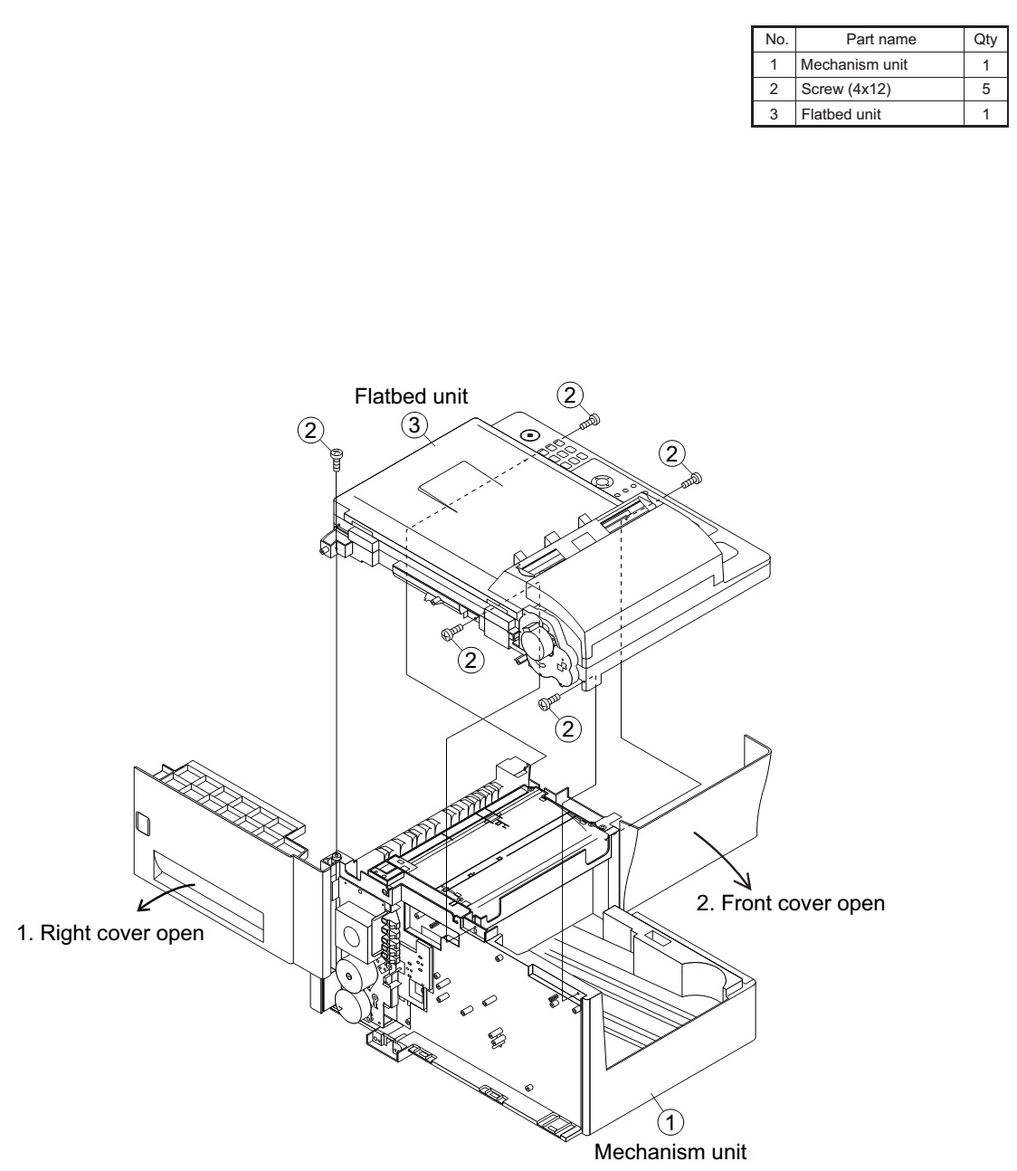
FLATBED UNIT
FLATBED COVER / SCANNER UNIT / FLATBED UPPER / DRIVE UNIT & FLATBED LOWER
RIGHT COVER / FRONT COVER / PAPER EXIT UNIT / OPTICAL UNIT [LSU] / FUSING UNIT
WIRING DIAGRAM