Thursday, June 24, 2021

How to enter the service mode of FUNAI LCD A3206 - 32 inch LCD TV, How to initialize, electrical adjustments, SMPS and backlight inverter schematic, White balance adjustment, Flicker adjustment


FUNAI 32" COLOR LCD TELEVISION - LCD-A3206 - LCD-B3206 -  LCD-C3206 - LCD-D3206

  Always respect voltages. While some may not be dangerous in themselves, they can cause unexpected reactions that are best avoided. Before reaching into a powered TV set, it is best to test the high voltage insulation. It is easy to do, and is a good service precaution.

Hot Chassis Warning
a.
Some TV receiver chassis are electrically connected directly to one conductor of the AC power cord and maybe safety-serviced without an isolation transformer only if the AC power plug is inserted so that the chassis is connected to the ground side of the AC power source. To confirm that the AC power plug is inserted correctly, with an AC voltmeter, measure between the chassis and a known earth ground. If a voltage reading in excess of 1.0V is obtained, remove and reinsert the AC power plug in the opposite polarity and again measure the voltage potential between the chassis and a known ground.
b. Some TV receiver chassis normally have 85V AC(RMS) between chassis and earth ground regardless of the AC plug polarity. This chassis can be safety-serviced only with an isolation transformer inserted in the power line between the receiver and the AC power source, for both personnel and test equipment protection.
c. Some TV receiver chassis have a secondary ground system in addition to the main chassis ground. This secondary ground system is not isolated from the AC power line. The two ground systems are electrically separated by insulation material that must not be defeated or altered.

Disassembly Flowchart
This flowchart indicates the disassembly steps for the cabinet parts, and the CBA in order to gain access to item(s) to be serviced. When reassembling, follow the steps in reverse order. Bend, route and dress the cables as they were.


Disassembly Method


HOW TO INITIALIZE THE LCD TELEVISION
To put the program back at the factory-default, initialize the LCD television as the following procedure.
How to initialize.
1. Turn the power off.
2. To enter the service mode,
while pressing [SETUP] button, press [STANDBY-ON] button on the TV unit.
- To cancel the service mode, press [STANDBYON] button on the remote control.
3. To initialize the LCD television, press “DISPLAY” button on the remote control unit.
4. Confirm "FF" indication on the upper left of the screen.

ELECTRICAL ADJUSTMENTs

Electrical adjustments are required after replacing circuit components and certain mechanical parts. It is important to perform these adjustments only after all repairs and replacements have been completed.
Also, do not attempt these adjustments unless the proper equipment is available.
Test Equipment Required
1. DC Voltmeter
2. Pattern Generator
3. Colour Analyzer
How to Set up the Service mode.
1. Turn the power off.
2. While pressing [SETUP] button, press [STANDBYON] button on the TV unit.
- To cancel the service mode, press [STANDBY-ON] button on the TV unit.

Initial Setting
General
Enter the Service mode.
Set the each initial data as shown on table.


Flicker Adjustment
This adjustment is needed when reparing T-CON CBA.
1. Enter the Service mode.
2. Press [2] button on the remote control unit. The following screen appears.

3. If Flicker Adjustment is not fit, the screen become the following.

4. Turn the VR1 on the LCD Module so that flash stops.

Purity Check Mode
This mode cycles through full-screen displays of red, green, blue, and white to check for non-active pixels.
1. Enter the Service mode.
2. Each time pressing [7] button on the service remote control unit, the display changes as follows.

Auto Calibration.
Purpose:
To bring the colour adjustment of each component into standard alignment.
Symptom of Maladjustment:

 If this adjustment is incorrect, component signals do not reproduce the corresponding color.

Gain Adjustment
1. Input white raster signal (5%=5 IRE, 100%=100 IRE) from Component jack.

2. Enter the service mode.
3. To enter the Auto Calibration. adjustment mode, press [5] button on the service remote control unit.
4. To start auto adjustment, press [CH UP] button on the service remote control unit.
- In the auto adjustment mode, “Please Wait” appears on the screen.
- Upon completion, “OK” and appears on the screen.
- If the auto adjustment failure, “ NG” appears on the screen.

Offset Adjustment.
5. Input white raster signal (5%=5 IRE) from Component jack.

6. Enter the service mode.

7. To enter the Auto Calibration adjustment mode, press [6] button on the service remote control unit.
8. To start auto adjustment, press [CH UP] button on the service remote control unit.
- In the auto adjustment mode, “Please Wait” appears on the screen.
- Upon completion, “OK” and appears on the screen.
- If the auto adjustment failure, “ NG” appears on the screen.

The following adjustment normally is not attempted in the field. Only when replacing the LCD Panel then adjust as a preparation.

White Balance Adjustment
*This adjustment is needed when repairing T-CON CBA.
Purpose: To mix red, green and blue beams correctly for pure white.
Symptom of Maladjustment: White becomes bluish or reddish.

1. Operate the unit for more than 20 minutes.
2. Input the White Purity.

3. Set the color analyzer to the CHROMA mode and bring the optical receptor to the center on the LCD-Panel surface after zero point calibration as shown.
Note: The optical receptor must be set perpendicularly to the LCD Panel surface.
4. [CVBS]
Enter the Service mode. Press “VOL DN” button on the remote control unit and select “C/D/S 1” mode.

[YUV]
Enter the Service mode. Press “VOL DN” button on the remote control unit and select “C/D/S 2” mode.
[RGB]
Enter the Service mode. Press “VOL DN” button on the remote control unit and select “C/D/S 3” mode.

5. [CVBS]----(APL 70%)
Press “6” button to select “DB 1(C/D/S 1)” for Blue adjustment. Press “4” button to select “DR 1(C/D/S 1)” for Red adjustment. When “x” value and “y” value are not within specification, adjust “DB 1(C/ D/S 1)” or “DR 1(C/D/S 1)”. Refer to “1. Initial Setting.”
[CVBS]----(APL 25%)
Press “3” button to select “COB 1(C/D/S 1)” for Blue adjustment. Press “1” button to select “COR 1(C/D/S 1)” for Red adjustment. When “x” value and “y” value are not within specification, adjust “COB 1(C/D/S 1)” or “COR 1(C/D/S 1)”. Refer to “1. Initial Setting.”
After adjusting (APL 25%), verify (APL 70%) again and adjust repeatedly until both values are within specification.
6. [YUV]----(APL 70%)
Press “6” button to select “DB 2(C/D/S 2)” for Blue adjustment. Press “4” button to select “DR 2(C/D/S 2)” for Red adjustment. When “x” value and “y” value are not within specification, adjust “DB 2(C/ D/S 2)” or “DR 2(C/D/S 2)”. Refer to “1. Initial Setting.”
[YUV]----(APL 25%)
Press “3” button to select “COB 2(C/D/S 2)” for Blue adjustment. Press “1” button to select “COR 2(C/D/S 2)” for Red adjustment. When “x” value and “y” value are not within specification, adjust “COB 2(C/D/S 2)” or “COR 2(C/D/S 2)”.  Refer to “1. Initial Setting.”
After adjusting (APL 25%), verify (APL 70%) again and adjust repeatedly until both values are within specification.
7. [RGB]----(APL 70%)
Press “6” button to select “DB 3(C/D/S 3)” for Blue adjustment. Press “4” button to select “DR 3(C/D/S 3)” for Red adjustment. When “x” value and “y” value are not within specification, adjust “DB 3(C/ D/S 3)” or “DR 3(C/D/S 3)”. Refer to “1. Initial Setting.”
[RGB]----(APL 25%)
Press “3” button to select “COB 3(C/D/S 3)” for Blue adjustment. Press “1” button to select “COR 3(C/D/S 3)” for Red adjustment. When “x” value and “y” value are not within specification, adjust “COB 3(C/D/S 3)” or “COR 3(C/D/S 3)”. Refer to “1. Initial Setting.”
After adjusting (APL 25%), verify (APL 70%) again and adjust repeatedly until both values are within specification.
8. Turn the power off and on again. (Main power button on the TV unit.)

Power [SMPS] and backlight board schematic.


Sunday, June 06, 2021

Philips VES15.1HE–LA CHASSIS Using VESTEL 17MB95M Main board – service mode, alignments, power (SMPS) board schematic, Wiring diagram

 VES15.1HE LA main board is driven by MStar SOC. This IC is a single chip IDTV solution that supports channel decoding, MPEG decoding, and media-centre functionality enabled by a high performance AV CODEC and CPU.

• Combo Front-End Demodulator
• A multi-standard A/V format decoder
• The MACEpro video processor
• Home theatre sound processor
• Internet and Variety of Connectivity Support
• Dual-stream decoder for 3D contents
• Multi-purpose CPU for OS and multimedia
• Peripheral and power management

Service Alignment Mode (SAM)

Specifications
• Operation minutes counter (maximum five digits displayed).
• Software version and option settings display.
• Option settings.

How to Activate SAM
To activate SAM, use one of the following methods:
• Press MENU button first. While main menu is on screen press
4725 consecutively. Do not allow the display to time out between entries while keying the sequence.
After entering SAM, the following items are displayed.

How to Store SAM Settings
All the changes which have been made are stored automatically. It is suffice to enter the new value and just exit.
How to Exit SAM
Use one the following method:
• Switch the set to STANDBY by pressing the mains button on the remote control transmitter or the television set.
Note: When the TV is switched “off” by a power interrupt while in SAM, the TV will show up in “normal operation mode” as soon as the power is supplied again. The error buffer will not be cleared.

Software Identification, Version, and Cluster
The software ID, version, and cluster will be shown in the main menu display of SAM, and CSM.
The screen will show: “AAAAAB-XX.YY”, where:
• AAAAA is the chassis name: VES11E_2.1.4n.
• B is the region indication: E = Europe, A = AP/China, U = NAFTA, L = LATAM.
• XX is the main version number: this is updated with a major change of specification (incompatible with the previous software version). Numbering will go from 01 - 99 and AA - ZZ.
- If the main version number changes, the new version number is written in the NVM.
- If the main version number changes, the default settings are loaded.
• YY is the sub version number: this is updated with a minor change (backwards compatible with the previous versions). Numbering will go from 00 - 99.
- If the sub version number changes, the new version.

Download the latest software
1. Point the web browser to http://www.philips.com/support.
2. Find information and software related to the TV.
3. Select the latest software update file and download it to the PC.
4. Insert a USB flash drive into one of the USB ports of the PC.
5. Decompress the downloaded ZIP file and copy it to the root directory of the USB flash drive.

Update the TV software
1. Unplug the mains power cord from your TV.
2. Insert the USB flash drive that contains the software update files.
3. Press and hold the OK button.
Note: If the USB flash drive is not detected after power up, disconnect it and re-insert it.
4. Plug the mains power cord back in while holding the OK button.
5. The led light will start to flash and blink.
6. The first time installation menu will appear.
7. Restart your TV. Your TV has now been updated.
Note:
• Do not remove the USB flash drive during the software update.
• If a power failure occurs during the update, do not remove the USB flash drive from the TV. The TV will continue the software update as soon as the power comes up again.
• If an error occurs during the update retry the procedure or contact the dealer.
• We do not recommend downgrading to an older version.
• Once the upgrade is finished, use the PC to remove the TV software from the USB portable memory.
• Software upgrade via an USB device can be done anytime by using hidden key combination,
‘Menu-1-5-0-5’ or via pressing the RED button at FTI screen in Hotel TV mode.
Software file name should be “VES151HE_upgrade.bin”.

How to Copy NVM Data to/from USB
Note:
This function is only valid for hotel TV.
Copy to USB
There are two steps and both are independent of each other.
Copy the updated welcome image to USB as “hotel_wel.png”
Copy from USB
There are two steps and both are independent of each other. If there is file named “hotel_wel.png” in directory “welcome_image”. It is copied to TV to use as welcome image.
Copy from USB device data to NVRAM. Just the reverse operation done by copy to USB call. Previously copied NVRAM files (Flashx.bin) are copied into TV. If there is no flash file or some of them are available on USB, the available ones are copied. If no USB is connected, nothing happens.
Note: For Clone function USB stick (Copy to USB - Copy from USB) must be formatted to FAT32. If USB is not formatted to FAT32 the other TVs will not accept cloned data and performance issues will result.

How to Edit S/N (Serial Number) & Model Number
Uploading Procedure To TV
Create “SerialNoModelNo.txt” file in an USB stick. Write the informations below on this text file.
SerialNo: xxx
ModelNo: yyy
Then apply USB operations. Power on/off.
Downloading Procedure from TV
Create “DownloadSerialModelNo.txt” file in an empty USB stick. Apply USB operations. After you applied USB operations, “SerialNoModelNo.txt” file will be created automatically in the USB stick.

LED Blinking problem
When the front LED blinks it indicates that the SSB has gone in protection mode. In the possibility of a short circuit, the LED light will blink at a 1 to 2 Hz frequency. It will continue to blink even after rebooting and until proper repairs are made. Check the DC-DC sections of the SSB as well as the power supply unit.
 
No Backlight Problem.
Backlight pin, dimming pin, backlight supply, stby on/off pin BACKLIGHT_ON/OFF pin should be “high”, when the backlight is ON. R119 must be “low” when the backlight is OFF. If it is a problem, please check Q10 and the panel cables. Also it can be tested in TP50 in main board.

No Picture via HDMI input
Check if HDCP key is valid. This can be done in CSM.
TV Will Not Start-up from Stand-by
Possible Stand-by Controller failure. Re flash the SW.
CI Module Problem
Supply, supply control pin, detect pins, mechanical positions of pins.CI supply should be 5V when CI module inserted. If it is not 5V please check CI_PWR_CTRL, this pin should be low.

Loudspeakers
Make sure that the volume is set to minimum during disconnecting the speakers in the ON-state of the TV. The audio amplifier can be damaged by disconnecting the speakers during ON-state of the set!
Display Option Code
This chassis does not use display option codes.

Staying in Stand-by Mode
This problem indicates a short on VCC voltages. Protect pin should be logic high while normal operation. When there is a short circuit protect pin will be logic low. If you detect logic low on protect pin, unplug the TV set and control voltage points with a multi-meter to find the shorted voltage to ground.
IR Problem
Check LED card supply on MB95M chassis.
No Signal Problem
Check tuner supply voltage; 5V_VCC, 3V3_TUNER and 1V8_TUNER. Check tuner options are correctly set in Service menu. Check AGC voltage at IF_AGC pin of tuner.
Remote Control Incompatibility
This TV set requires the original remote control that it was shipped with. Only the original remote control guarantees full compatibility and operation and a healthy service operation.

General Alignment Conditions
Perform all electrical adjustments under the following conditions:
• Power supply voltage: 90 - 264 VAC, 50/ 60
± 3 Hz.
• Connect the set to the mains via an isolation transformer with low internal resistance.
• Allow the set to warm up for approximately 15 minutes.
• Measure voltages and waveforms in relation to correct ground (e.g. measure audio signals in relation to AUDIO_GND).
Caution: It is not allowed to use heat sinks as ground.
• Test probe: Ri > 10 M
W, Ci < 20 pF.

Hardware Alignments
Not applicable.
Software Alignments
Not applicable.

White Point Alignments
Steps for white point alignment are listed below
• Run the PC
• Connect the USB cable of DB07 board.
• Run the video pattern generator, adjust %80 white pattern.
• Run the color Analyzer CA210, make the CAL the probe.
Calibration steps
• Select the CAL position on the probe.
• Press button 0-CAL.
• Wait 5 seconds.
• Select MEAS position on the probe.
• Wait a minimum of 15 mins, avg. time is 45 mins.
• Connect the scart cable to TV.
• Place the probe across the display (center position, 0.5 cm at 90 degrees.
• Check the PC, select the COM port.
• Select the model type OEM.dat.
• Press the START button.
• Wait for the software to set all modes (normal, cool, warm)
• Wait for the OK-READY sign.

 Default White Point Alignment Values

SSB LAYOUT

Power Supply Unit
Before checking other parts first check whether fuse on the PSU is not broken. Always replace a defective fuse with one with the correct specifications! This part is available in the regular market.
Consult the Philips Service web portal for the order codes of the boards.
The output voltages to the chassis are:
• +5V / +3V3 / 12 V- STANDBY
• +5 V / +12V (on-mode)
• +24V for audio circuit, (on-mode)

USB Interface
The SOC has two input port for USB, therefore air mouse, internal wi-fi interface and USB2 are combined with HUB. This property is optional. If air mouse and Wi-Fi interfaces are not aligned, two USB are connected directly to main IC.

Power Management
The on-board DC/DC converters receive the following voltages from the PSU (depending on set execution):
• +3.3 VSB, for standby mode.
• +5 VSB, for standby mode.
• +12 VSB, for standby mode.
• +3.3 V, for on mode.
• +5 V, for on mode.
• +24 V, for on mode, audio power.
Circuit Description
System power
The main board power is received at connector CN3 or CN2 from power board, to receive the power and signals from the PSU.

CN-2 AND CN-3 connectors’ overview

Wiring diagram 19 inch
Wiring diagram 24 inch
Wiring diagram 28 inch
Wiring diagram 32 inch

Wiring diagram 40 inch

Wiring diagram 48 inch

Power board (SMPS) circuit diagrams (Schematics)


Power circuit diagram


Audio, headphone schematic


Saturday, May 29, 2021

Panasonic 50 inch Class 1080p Plasma HDTV TC-50PS14-GPF12DU Chassis – Service mode, Adjustments, LED blinking codes, SMPS circuit diagram [Schematic], Troubleshooting

 Power source - AC 120 V, 60 Hz

How to enter into Service Mode

While pressing [VOLUME ( - )] button of the main unit, press [INFO] button of the remote control three times within 2 seconds.

Service mode screen

Contents of adjustment mode
• Value is shown as a hexadecimal number.
• Preset value differs depending on models.
• After entering the adjustment mode, take note of the value in each item before starting adjustment.

How to exit
Switch off the power with the [POWER] button on the main unit or the [POWER] button on the remote control.

Service tool mode:  How to access
1. Select [SRV-TOOL] in Service Mode.
2. Press [OK] button on the remote control.

Display of SOS History
SOS History (Number of LED blinking) indication.
From left side; Last SOS, before Last, three occurrence before, 2nd occurrence after shipment, 1st occurrence after shipment.
This indication except 2nd and 1st occurrence after shipment will be cleared by [Self-check indication and forced to factory shipment setting].
POWER ON TIME/COUNT
Note : To display TIME/COUNT menu, highlight position, then press MUTE for (3sec).
Time : Cumulative power on time, indicated hour : minute by decimal
Count : Number of ON times by decimal
Note : This indication will not be cleared by either of the self-checks or any other command.
Exit
1. Disconnect the AC cord from wall outlet.

Hotel mode
Check of the IIC bus lines:  How to access
Self-check indication only:
Produce TV reception screen, and while pressing [
VOLUME ( - )] button on the main unit, press [OK] button on the remote control for more than 3 seconds.
Self-check indication and forced to factory shipment setting:
Produce TV reception screen, and while pressing [
VOLUME ( - )] button on the main unit, press [MENU] button on the remote control for more than 3 seconds.
Exit
Disconnect the AC cord from wall outlet.

Restrict a function for hotels.
2. Access command to the Hotel mode setup menu
In order to display the Hotel mode setup menu, please
enter the following command (within 2 second).
[TV] : Vol. [Down] + [REMOTE] : INPUT (3 times)
Then, the Hotel mode setup menu is displayed.

3. To exit the Hotel mode setup menu
Disconnect AC power cord from wall outlet.
4. Explain the Hotel mode setup menu.

Troubleshooting
Use the self-check function to test the unit.
1. Checking the IIC bus lines
2. Power LED Blinking timing.

Power LED Blinking timing chart
1. Subject
Information of LED Flashing timing chart.
2. Contents
When an abnormality has occurred the unit, the protection circuit operates and reset to the stand by mode. At this time, the
defective block can be identified by the number of blinks of the Power LED on the front panel of the unit.

No Power
First check point
There are following 2 states of No Power indication by power LED.
1. No lit
2. Red is lit then turns red blinking a few seconds later


Local screen failure

Adjustment Procedure

1. Input a white signal to plasma video input.
2. Set the picture controls as follows.
Picture menu: Vivid
Normal: Set
Aspect: Full
Caution
1. First perform Vsus adjustment.
2. The Vscn voltages are measured from the Vad (Vad_base), but may be measured from the GND (GND_base) in an unavoidable case,

Adjustments
Adjust driver section voltages referring the panel data on the panel data label.
Check or adjust the following voltages with the multimeter.

Initialization Pulse Adjust
1. Input the White signal to plasma video input.
2. Set the picture controls as follows.
Picture menu : Vivid
Normal : Set
Aspect : Full
3. Connect Oscilloscope to TPSC1 (SC).
Check the voltage (T2) at 100μs period on the down slop.

P.C.B. (Printed Circuit Board) exchange

Caution
1. To remove P.C.B., wait 1 minute after power was off for discharge from electrolysis capacitors.
Quick adjustment after P.C.B. exchange
Adjust the following voltages with the multimeter.

White balance adjustment

POWER BOARD - ETX2MM747AFK: schematic


Tuesday, May 18, 2021

Sharp LC48CFG4042E, Sharp LC49CFE4041E – How to enter the service mode, Software update, Service mode adjustments


LC-48CFG4042E, LC-49CFG4041E, LC-49CFE4042E – Sharp LCD TV-service mode, service mode adjustments, software update, Panel and EMC setting and more

MSD3463 Factory Menu Specification

How to Enter Factory Menu
Press the RC buttons in this sequence: “Menu 1 1 4 7” to enter the factory menu.

INTRODUCTION
SHIPPING INIT:
TV Initialization to set default TV parameters. Designed for Shipment.
AGING MODE: TV aging mode switch.
ADC ADJUST: Change ADC parameters
PICTURE SETTING: Change Picture Setting
SOUND SETTING: Change Sound Setting
GENERAL SETTING: Some other settings usually used, and also for Debug.
PANNEL SETTING: Change panel parameters like BitMap, ODD.EVEN and Etc.
EMC SETTING: Some settings may affect EMC.
SYSTEM INFO: Display system information.
BOARD INIT: Factory reset.
SW UPGRADE: Software update item.

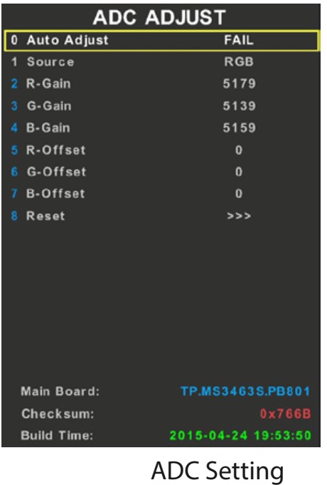
ADC ADJUST & WHITE BALANCE AUTO ADJUST
It’s for adjusting the YPBPR and PC color. Press key “right” or “ok” to enter the subpage.
Auto Adjust: Start to auto color to get ADC value.
Source: Set source for adjusting
R-Gain: Display current ADC R value.
G-Gain: Display current ADC G value.
B-Gain: Display current ADC B value.
R-Offset: Display current ADC R offset value.
G-Offset: Display current ADC G offset value.
B-Offset: Display current ADC B offset value
Reset: Reset to default values.

PICTURE
Source:
Choose source
Picture Mode: Change picture mode parameters
Picture Curve: Picture mode parameter curve.
WB Adjust: White Balance parameter setting
Over scan: Over scan setting
PQ Advanced: For PQ Adjustment.
Gamma: Preset several Gamma Curves, for PQ debug.
DLC: Preset several Curves, for PQ debug.
HDMI RGB Range: Change Limit range or Full Range.

PICTURE MODE
Source:
Choose sources
Picture Mode: Select picture mode which is same with main menu.
Contrast: Adjust contrast which is same with main menu.
Brightness: Adjust brightness which is same with main menu.
Color: Adjust Color which is same with main menu.
Sharpness: Adjust Sharpness which is same with main menu.
Tint: Adjust tint which is same with main menu.

PICTURE CURVE
Adjust the real value of main menu from 0 to 100
Source: Choose source
Contrast: Adjust the real contrast for main menu from OSD 0 to OSD 100.
Brightness: Adjust the real brightness for main menu from OSD 0 to OSD 100.
Color: Adjust the real color for main menu from OSD 0 to OSD 100.
Sharpness: Adjust the real sharpness for main menu from OSD 0 to OSD 100.
Tint: Adjust the real tint for main menu from OSD 0 to OSD 100.

CONTRAST
Contrast-0:
The real value of main menu contrast OSD 0
Contrast-25: The real value of main menu contrast OSD 25
Contrast-50: The real value of main menu contrast OSD 50
Contrast-75: The real value of main menu contrast OSD 75
Contrast-100: The real value of main menu contrast OSD 100
The Brightness, Color, Sharpness, Tint are same with the contrast.

WB [White Balance] ADJUST
White-Balance Adjustment
This page only for current source White Balance Adjustment.  Different source may have different values. There are Warm, Cool, Normal modes and save every separate source. We can change the R-GAIN, G-GAIN, B-GAIN, R-OFFSET, G-OFFSET, B-OFFSET.
SYNC ALL: SYNC the white balance of the current source to all other sources.

White Balance
 Load 80% White pattern from signal generator
 Enter Factory Menu by pressing MENU + 1147
 Choose 3 PICTURE SETTING
 Choose 3 WB ADJUST
 Change 0 SOURCE to HDMI
 In 1 COLOUR TEMP choose Warm/Normal/Cold
 Change R-GAIN/G-GAIN/B-GAIN to meet specification

OVERSCAN
This page can adjust over scan.
Note: Over scan should check with every timing.

PQ ADVANCED
PQ Adjustment Page
Adjust luminance, Colors, peaking, NR and etc.

SOUND
Source:
Choose source
Sound Mode: BASS, TREBLE, EQ-Settings.
Volume Curve: Adjust volume curve.
Audio Pre-scale: Adjust the power of current source.
Audio AVC: For Software Designer Only
PEQ: For Software Designer Only
Audio DRC: For Software Designer Only
Treble/Bass Range: Adjust the Treble/Bass range
SPDIF Audio Delay: Adjust the SPDIF Audio delay.

VOLUME CURVE
Volume Offset:
User overall volume control, every source has a unique value.
VOL1–VOL100: All sources share a same value, make sure the next value bigger than the before.

GENERAL SETTING
Power Mode:
On/Standby/Last boot status.
LOGO: Set boot logo on or off.
Test Pattern: Test pictures from IC which can help to judge panel issue or not.
Channel Export: Export channel table.
Channel Import: Import channels table to TV.
Watch Dog: watch dog switch.

DEBUG
UART Debug:
For Software Designer only
QMAP: Map adjustment
Timer Test: Speed up timer

PANEL and EMC SETTING

SYSTEM INFORMATION

SW UPGRADE
Upgrade TV: update item
Bin Name: Software bin name.

Upgrading the software
MSD3463 has two kinds of chips: MSD3463GSA and MSD3463GU. Please make sure that you get
the correct upgrading file for a certain chipset (refer to the chart below).   Introducing 4 upgrading methods one by one: User menu Upgrading, Power on Upgrading, Factory Setting Upgrading, ISP Upgrading. The former three are most commonly-used.

Preparation
This step only applies to power integrated board.
Prepare mini power board(CN.UPGRADE01) for upgrading.

Connect the mini board with main board as below:

Make sure connect the 12V to 12V and GND to GND, or it will cause hardware damage.
 The main board should be connected to mains to work if we do not use the CN.UPGRADE01 board. The power module of main board have more than thousands of volts at working. It is easily leads personal injury or damage to equipment if  mistakenly touch the main board or some objects fallen into the main board during the upgrading procedure. So  use the CN.UPGRADE01 board to reduce the risk of upgrading.

Please keep the electricity ON in the upgrade process.
Operation Procedure
Copy the Upgrading File (SW) to a USB disk and then insert it to the USB port. Search for the SETUP and select Software Update by Left or Right  remote control key on User OSD Menu. The pictures below are the upgrading procedure for your reference:

Upgrade Prompt
When upgrading, the TV set will light panel according to the panel parameter, and display the progress bar. If the panel parameter of board matches the panel, you will see the following image:

100% indicates the upgrade finished, and TV will auto reboot after user menu upgrading finished.
 Upgrade Flashing Status
You can judge the upgrade progress by flashing of the remote control LED light:
Upgrading:
Red 1000ms Green 1000ms alternates, the TV set will turn to Upgrade succeed or Upgrade Failed status after the upgrading process.
Main program upgrade succeed:
Red 250ms Green 250ms alternates, flashing before power off.
Main program upgrade Failed:
Red 1750ms Green 250ms alternates, flashing before power off.
Notes: In the upgrade process, as timer software is used to control flashing, situations such as LED light stuck when creating partition of flash, is normal phenomenon.
Power On Upgrading
Copy the SW to a USB disk, link it to the USB port, Re-power on, if the LED blinks continually, it means the upgrading is on process, while the LED light off means the upgrading has been completed.

Factory Setting Upgrading
Press <MENU>+1147 to enter the factory setting, search for the “Upgrade” item by the remote control, just like the picture below, then you can follow the steps in the screen.


Install USB driver. Make sure the USB ISP tool is connected to PC before setup


HOTEL MODE
To enter Hotel mode you need press buttons on RC in following sequence: MENU 7 9 0 6.
Structure of Hotel menu:
1. Hotel Mode – on/off hotel mode
2. Source Lock – you can lock any source
3. Default Source – source which appears after turn on TV
4. Default Prog – channel which appears after turn on TV
5. DTV channel type – type of channel which appears after turn on TV
6. Default volume – volume which will be set itself after turn on TV
7. Max volume – maximum volume which can be set
8. Import Database – import all channels and settings from USB
9. Export Database – export all channels and setting to USB
10. Clear Lock – reset all hotel mode settings.