Sunday, July 30, 2017

Power amplifier schematic – 100Watts, using 6L6 (Audio output) and 12AX7 (pre-amp) tubes

6L6 can be substituted by 6N3C tube (Russian), provided a very small change with the heater voltage.
The heater voltage for 6L6 is 6.6VAC and for the 6N3C is 6.3VAC.
The substitute for 12AX7 is ECC83
Matched pairs of 6L6 or 6N3C should be used at the output stage. Otherwise, some bias adjustments should be done to compensate the gain of the output valves. (R42, R24, R25, R26 and R27) are the adjusting resistors for this purpose. (R42) adjusts the common bias, and the rest are meant to adjust individual valve bias. 
Use good quality valve sockets to avoid distortion. Some sockets may have poor contacts, and should be avoided. Sockets with gold plated contacts are recommended.
Pre-amplifier schematic
Push-pull power amplifier schematic
Pin numbers are indicated with one of the 6L6 valve at (top-left) in the circuit. Pin configuration of 6L6 and 6N3C are similar. 
Click on the schematics to magnify

Friday, July 28, 2017

Sony HCD-GT3D DVD receiver – Error codes, how to enter service mode, service adjustments, how to eject disc in emergency, Main Amp circuit diagram and more …

The laser diode in the optical pick-up block may suffer electrostatic break-down because of the potential difference generated by the charged electrostatic load, etc. on clothing and the human body.  During repair, pay attention to electrostatic break-down and also use the procedure in the printed matter which is included in the repair parts.  The flexible board is easily damaged and should be handled with care.
The laser beam on this model is concentrated so as to be focused on the disc reflective surface by the objective lens in the optical pickup block. Therefore, when checking the laser diode emission, observe from more than 30 cm away from the objective lens.
Abbreviation
AR : Argentina model
AUS : Australian model
E4 : African model
EA : Saudi Arabia model
LA9 : Latin-American model
MY : Malaysia model
RU : Russian model
TH : Thai model
REPLACING THE IC001, IC002, IC101, IC105, IC106, IC301, IC302 AND IC303 ON THE MOTHERBOARD BOARD
IC001, IC002, IC101, IC105, IC106, IC301, IC302 and IC303 on the MOTHERBOARD board cannot exchange with single.
When these parts on the MOTHERBOARD board are damaged, exchange the entire mounted board.
REPLACEMENT OF THE MS-476 BOARD
When the MS-476 board is defective, exchange the entire LOADING COMPLETE ASSY
RELEASING THE DISC TRAY LOCK
The disc tray lock function for the anti-theft of an demonstration disc in the store is equipped.
Releasing Procedure
1. Press [Power] button to turn the power on.
2. Press [FUNCTION] button and turn the [MULTI CONTROL)
Knob to select “DVD/CD” function, then press [ENTER] button.
3. Press the [ENTER] button and [VOCAL FADER] button simultaneously and hold down for around 3 seconds.
4. The message “UNLOCKED” is displayed and the disc tray is unlocked.
Note: When “LOCKED” is displayed, the slot lock is not released by turning power on/off with the [Power] button.
REPLACING THE IC1001 ON THE DAMP BOARD AND THE COMPLETE DAMP BOARD
When IC1001 on the DAMP board and the complete DAMP board are replaced, it is necessary to spread the heat-sink compound between parts and heat sink.
REPLACING MOTHERBOARD BOARD OR BLUETOOTH MODULE OR RC-S730 (WW) BOARD
When the MOTHERBOARD board or BLUETOOTH module or RC-S730 (WW) board are replace execute the below service mode.
Pairing this system with a Bluetooth device
1. Press the [Power] button to turn the power on.
2. Place the Bluetooth device within 1 meter (3 feet) from the system.
3. Press BLUETOOTH on the unit to select Bluetooth function.
“BT AUDIO” appears in the display panel.
4. Hold down BLUETOOTH on the unit for 2 seconds or more.
“PAIRING” flashes in the display panel.
5. Perform the pairing procedure on the Bluetooth device.
6. Select the model number of the unit on the display of the Bluetooth device.
For example, select “SONY : MHC-GT3D”. If passkey is required on the Bluetooth device, enter “0000”.
7. Perform the Bluetooth connection on the Bluetooth device.
8. When pairing is completed and the Bluetooth connection is established, the Bluetooth device name appears in the display panel.
9. To cancel pairing operation, hold down BLUETOOTH on the unit for 2 seconds or more until “BT AUDIO” appears in the display panel.
Connecting with a Smartphone by one touch (NFC)
[The operation in this mode must use a NFC-compatible Smartphone (Smartphone with a built-in NFC function [OS: Android 2.3.3 or later, excluding Android 3.x])]
1. Press the [Power] button to turn the power on.
2. Download and install the app “NFC Easy Connect”.  Download the free Android app from Google Play by searching for “NFC Easy Connect”.
3. Start the app “NFC Easy Connect” on the Smartphone.  Make sure that the application screen is displayed.
4. Touch the Smartphone to the N-Mark on the system until the Smartphone vibrates.
Complete the connection by following the instructions displayed on the Smartphone.
5. When pairing is completed and the Bluetooth connection is established, the Bluetooth device name appears in the display panel.
Playing music from a Bluetooth device
For a Bluetooth device
1. Press the [Power] button to turn the power on.
2. Press BLUETOOTH on the unit to select Bluetooth function. “BT AUDIO” appears in the display panel.
3. Establish connection with the Bluetooth device.  Press BLUETOOTH on the unit to connect to the last connected Bluetooth device.  Perform the Bluetooth connection from the Bluetooth device if the device is not connected.  Once the connection is established, the Bluetooth device name appears in the display panel.
4. Press N.
Depending on the Bluetooth device,
> you may have to press N twice.
> you may need to start playback of an audio source on the Bluetooth device.
For an NFC-compatible Smartphone
Press the [Power] button to turn the power on.
Touch the Smartphone to the N-Mark on the system to establish the Bluetooth connection.  Start playback of an audio source on the Smartphone. For details on playback, refer to the operating instructions of your Smartphone.
To disconnect the Bluetooth device For a Bluetooth device
Press BLUETOOTH on the unit.
“BT AUDIO” appears in the display panel.
For an NFC-compatible Smartphone
Touch the Smartphone to the N-Mark on the system again.
To erase all the pairing registration information perform COLD RESET test mode.
COLD RESET
The cold reset clears all data including preset data stored in the data flash to initial conditions included history mode data. Execute this mode when returning the set to the customer.
1. Press [Power] button to turn on the system.
2. Press Stop button and [S4 TUNING + >>] button simultaneously for 3 seconds.
3. “COLD RST” appears on the fluorescent indicator tube.
After that, the fluorescent indicator tube will display “SONY DEMO”. The set will automatically Power ON and Power OFF again, and the system is reset.
HOW TO OPEN THE TRAY WHEN POWER SWITCH TURN OFF [No Power]
1: After the side panel and top panel are removed, this work is done.
2: Prepare the thin wire (clip etc. processed to the length of 8 cm or more).
Click on the pictures to Magnify
PANEL TEST MODE
This mode is used to check the fluorescent indicator tube, LEDs, keys, [VOLUME/DJ CONTROL] jog, model, destination and software version.
1. Press [Stop] button and [S3 TUNING – <<.] button simultaneously and hold 3 seconds.
2. All LEDs and segments in fluorescent indicator tube are lighted up.
3. When you want to enter to the software version display mode, press [S2 +] button.
The model information appears on the fluorescent indicator tube.
Press [S2+] button again to view the destination information.
4. During the destination information display, press [S2 +] button. Each time [S2 +] button is pressed, the fluorescent indicator tube shows the version of each category software in the following sequence: SC, MTK, OPU, UI, PF, SUB, SYS, CD, CMA, CMB, ST, TA, TM and return back to model information display.
5. When [Stop¬] button is pressed while the version numbers are being displayed except model and destination, the date of the software creation appears. When Stop button is pressed again, the display returns to the software version display.
6. When [ENTER] button is pressed after all LEDs and segments in fluorescent indicator tube light up, alternate segments in fluorescent indicator tube and LEDs would light up, all Party
Light LEDs would light up in red color. If you press [ENTER] button again, another half of alternate segments in fluorescent indicator tube and LEDs would light up, all Party Light LEDs
would light up in green color. Pressing [ENTER] button again would cause all segments in fluorescent indicator tube and LEDs light up, all Party Light LEDs would light up in blue color. Pressing [ENTER] button again would turn off all segments in fluorescent indicator tube and all LEDs including Party Light LEDs.
7. Press [S1 –] button, the key check mode is activated.
8. In the key check mode, the fluorescent indicator tube displays “K0 V0E0”.  Each time a button is pressed, “K” value increases. However, once a button has been pressed, it is no longer taken into account. After all the buttons have been pressed, "K" value will toggle between "OK" and "K24".
“V” value increases in the manner of 0, 1, 2, 3 ... if [VOLUME/ DJ CONTROL] knob is turned clockwise, or it decreases in the manner of 0, 9, 8, 7 ... if [VOLUME/DJ CONTROL] knob is turned counterclockwise.
“E” value increases in the manner of 0, 1, 2, 3 ... if [MULTI CONTROL] knob is turned clockwise, or it decreases in the manner of 0, 9, 8, 7 ... if [MULTI CONTROL] knob is turned
counterclockwise.
9. To release from this mode, press the buttons in the same manner as step 1, or disconnect the power cord.
USER RESET
The user reset clears all data including preset data stored in the data
flash to initial conditions exclude history mode data.
1. Press [Power] button to turn on the system.
2. Press [ENTER] button and [S4 TUNING +>>] button simultaneously for 3 seconds.
3. “RESET” appears on the fluorescent indicator tube. After that, the fluorescent indicator tube becomes blank for a while, and the system goes to demo mode.
DISC TRAY LOCK MODE
This mode let you lock the disc tray. When this mode is activated, the disc tray will not open when [Eject] button is pressed. The message “LOCKED” will be displayed on the fluorescent indicator
tube. This mode only applied when there is disc on the tray.
1. Press [Power] button to turn on the system.
2. Press [FUNCTION] button and turn the [MULTI CONTROL] knob to select “DVD/CD” function, then press [ENTER] button.
3. Press [ENTER] button and [VOCAL FADER] button simultaneously and hold down until “LOCKED” or “UNLOCKED” displayed on the fluorescent indicator tube (around 3 seconds).
Bluetooth PAIRING HISTORY CLEAR
It can clear the Bluetooth pairing history.
1. Press [Power] button to turn on the system.
2. Press [-PAIRING BLUETOOTH] button to turn the Bluetooth function.
3. Press two buttons of [ENTER] and [S1 –] simultaneously for 3 seconds.
4. The message “BT HIST” รจ “CLEAR” is displayed on the fluorescent indicator tube, and the pairing history of Bluetooth is cleared.
HISTORY MODE
This mode is used to check important data stored in the system when PROTECTOR happened.
1. During demo mode, press [Stop­] button and [S2 +] button for 5 seconds to mode into history mode.
2. Press the [S4 TUNING +>>|] button or [S3 TUNING – |<<.] button to check history data stored.
To release from this mode, press [Power] button.
Protect Type & Description
DVD COLOR SYSTEM MODE
This mode let you change the color system of the video output from PAL to NTSC or vice-versa.
1. Press [Power] button to turn on the system.
2. Press [FUNCTION] button and turn the [MULTI CONTROL] knob to select “DVD/CD” function, then press [ENTER] button.
3. Press [ENTER] button and [MIC ECHO] button simultaneously and hold for 3 seconds.
4. The message “PAL” or “NTSC” appears on the fluorescent indicator tube.
* To release from DVD Color System Mode
1. Once the color system has been selected, the mode is fixed there after. If you wish to change the mode again, perform the above item 2 again.
DVD SERVICE MODE
This mode let you make diagnosis and adjustment easily by using the remote commander and the TV. The instructions, diagnostic results, etc. are given on the on-screen display.
To enter to DVD Service Mode
1. Press [Power] button to turn on the system.
2. Press [FUNCTION] button and turn the [MULTI CONTROL] knob to select “DVD/CD” function, then press [ENTER] button.
3. Press [SOUND FIELD] button and [VOCAL FADER] button simultaneously and hold 3 seconds.
4. The message “SERVICE IN” appears on the fluorescent indicator tube.
The display of the “Model Name” of the “Remocon Diagnosis Menu” change with the model and the destination appears on screen display. Refer to below on the model name.
MHC-GT3D: GV2
5. To execute each function, press its number by using numeric button on the remote commander.
6. To release from this mode, press [Power] button to turn off the system.
Execute IOP Measurement
In order to execute IOP measurement; the following standard procedures must be followed.
1. From the Top Menu of Remocon Diagnosis Menu, select “2. 
Drive Manual Operation” by pressing the [2] button on the remote commander. The following screen appears on the onscreen display.
2. Select “3. Manual Adjustment” by pressing the [3] button on the remote commander. The following screen appears on the on-screen display.
3. Select “6. Iop:” by pressing the [6] button on the remote commander.
4. Wait until a hexadecimal number appears in the on-screen display as below:
5. Convert data from hexadecimal to decimal by using conversion table.
6. Please find the label on the rear of the BU (Base Unit).
The default IOP value is written in the label.
7. Subtract between these two values.
8. If the remainder is smaller than 93 (decimal), then it is OK.
However if the value is higher than 93, then the BU is defective and need to be change.
9. Press [RETURN] button on the remote commander to return to previous menu.
10. Press the [0] button on the remote commander to return to the Top Menu of Remocon Diagnosis Menu.
11. Press [Power] button to turn off the system.
Check Emergency History
To check the emergency history, please follow the following procedure.
1. From the Top Menu of Remocon Diagnosis Menu, select “3. Emergency History” by pressing the [3] button on the remote commander. The following screen appears on the onscreen display.
2. You can check the total time when the laser is turned on during playback of DVD and CD from the above menu. The maximum time, which can be displayed are 999h 59min.
3. You can check the error code of latest 10 emergency history from the above menu. To view the previous or next page of emergency history, press the [|<<] button or [>>|] button on the remote commander. The error code consists of “Error Code”, “Parameter of error code” and “Time of error 
Error codes
01: Communication error (No reply from syscon)
02: Syscon hung up
03: Power OFF request when syscon hung up
19: Thermal shutdown
24: MoveSledHome error
25: Mechanical move error (5 Changer)
26: Mechanical move stack error
30: DC motor adjustment error
31: DPD offset adjustment error
32: TE balance adjustment error
33: TE sensor adjustment error
34: TE loop gain adjustment error
35: FE loop gain adjustment error
36: Bad jitter after adjustment
40: Focus NG
42: Focus layer jump NG
51: Spindle stop error
52: Open kick spindle error
60: Focus on error
61: Seek fail error
62: Read Q data/ID error
70: Lead in data read fail
71: TOC read time out (CD)
80: Can’t buffering
81: Unknown media type
To clear the Laser Hours 
Press the [ DISPLAY] button and then press the [CLEAR] button. The data for both CD and DVD data are reset.
To clear the Emergency History
Press the [DVD TOP MENU] button and then press the [CLEAR] button.
The error code for all emergency history would be reset.
To clear the Initialize Setup Data
Press the [DVD/TUNER MENU] button and then press the [CLEAR] button on the remote commander.
To return to the Top Menu of Remocon Diagnosis Menu
Press the [0] button on the remote commander.
* Check Version Information
To check the version information, please follow the following procedure.
1. From the Top Menu of Remocon Diagnosis Menu, select “4.
Version information” by pressing the [4] button on the remote commander.
To return to the Top Menu of Remocon Diagnosis Menu, press the [0] button on the remote commander.
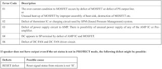
SMPS Board Diagnosis Flow
SCHEMATIC DIAGRAM - DAMP Board

Thursday, July 27, 2017

Grundig LCD TV Power Supply (SMPS VTY194-32) schematic for 22, 28, 32, 40 and 48 inch

For Models:
22QUER521, 22QUER4400, 22QUER4421, 22QUER5420, 22QUER5400,
22QUER5421, 22VLE5421, 22VLE5520, 28VLE4400, 28VLE4401,
28VLE4500, 28VLE5401, 28VLE5401, 28VLE5500, 32QUER555,
32QUER555, 32QUER4400, 32QUER4401, 32QUER5400, 32QUER5400,
32QUER5405, 32QUER5405, 32QUER5406 , 40QUER521, 40QUER555,
40QUER685, 40VLE4420, 40VLE4421, 40VLE5420, 40VLE5421, 40VLE5425,
48QUER555, 48QUER685, 48QUER4420, 48QUER4421, 48QUER5420, 48QUER5421 
Hamburg 
28CLE5407, 32CLE5407, 40CLE5427, 48CLE5427.
PWB - component and foil side
Schematic [Circuit diagram]
Click on the pictures to magnify

Saturday, July 22, 2017

Guitar amplifier schematic – used ICs: MC4558, TDA7294

Simple and very sensitive circuit.  Can be assembled easily on a perforated universal PWB.  Keep all the input leads very short in length to avoid input interference.  Use high quality shield wire to input signals.  Easily available ICs are used.
The output IC TDA7294 should be mounted on aluminium extruded heat-sink, Use of heat-sink compound is a must.
Pin number 14 of TDA7294 is the audio output 
In the given circuit diagram, the drawing is missed. Note it. 
Click on the schematic to zoom in

Wednesday, July 19, 2017

Loewe Concept L 42 Platinum, Loewe Concept L 42 Anthracite – Plasma TV – faults, reset, software update, Service mode and other adjustments

If a repair exchange has to be carried out, special care has to be taken of the so called E/X Tube. Via this sealed glass tube the panel is bleeded first, after that it becomes filled with gas. If this tube becomes broken, the panel is totally lost. Also when changing the panel, take care of the flex cables, any damages will also lead to a total loss of the panel, as those cables are bonded between the glass layers of the panel.
On the so called Type Labels you will find the panel type and the serial number of the panel. This information should be noted on the delivery notes in case of repair exchange.
Schematic Configuration
The schematic configuration of the panel shows, which PCBs belong together and which signals are conducted to the panel. The mentioned voltages Vs, Va and Vcc are from the PSU, which is part of the panel. Any exchange of the PSU by untrained persons is not recommended, as the voltages on the PSU have to be adapted to the corresponding panel.
General Reset
In the service menu (open with ”8640”, ) under the sub-menu ”reset all” a complete reset can be done.
CAUTION: Here the operating hours as well as the channel storage will be erased.
Over temperature - switch off
”WARNING” will appear, as soon as the temperature on the AV3 electronics exceeds 60DegC (Temperature 1)..
The unit will be switched to Stand By, the red LED is lit as soon as the temperature on the AV3 electronics exceeds 65DegC (Temperature 2)
It is possible to switch on the unit again via remote control.
The unit will be switched to Stand By, the red LED starts to blink as soon as the temperature on the AV3 electronics exceeds 70DegC (Temperature 3). It is not possible to switch on the unit again via remote control.  As soon as the temperature is below 60DegC, the LED stops blinking, it is possible to switch on the unit again.
Software Update
You need:
Update Program ”FlashUpgrader.exe” (for Windows 98 and Windows ME) or ”FlashUpgraderNT.exe” (for Windows NT4.0, Windows 2000 as well as Windows XP). Under Windows 95 the update is not possible.
Actual software (the update software as well as the actual software release for your device is available as zip file at your LOEWE service
Null Modem cable (serial date cable (RS232) with 9 pin female connector on both sides, the wires must be crossed)
Update:
Unpack Update Program and new Software into a new directory.
Switch off unit (mains switch).
Start Update-Program.
Select via”Choose...” file ” *.inf” in the new directory with the firmware data.
Set ”Connection” to ”serial”, select the used Com port as well as the Baud—rate (recommended 115200).
All other options remain on ”default” position.
Click on “Flash” anklicken, the program is set to stand by.
Switch on the device using the mains switch. The program starts automatically; the progress is shown on the display. Depending on the selected Baud—rate, the update takes about 3to6 minutes.
Typical Faults
In the case of malfunction, it is recommended to check the external wiring before opening the unit:
Mains power available?
Are the corresponding signal cables connected?
Is there a signal available from the external sources?
Is the corresponding signal source selected?
Also after opening the unit it is recommended to check the internal wiring and connectors to exclude any loose contact.
No display (on all signal modes)
Check In /Outputs of power supply. 
Not possible to switch unit on (remains in Standby)
Check IR remote control (batteries!)
Reinstall software 
Check AV3-electronic 
Missing lines or columns
Check display 
Pixel faults
Due to technological reasons single pixels or sub pixels might fail on TFTs as well as on Plasma displays. 
As long as the number of faults is within the limits mentioned in the specification, there is no device defect exists.
Missing colors
Check data cable
Check AV3
Check display
Channel search not working / not working properly
Check AV3
Flat-display connectors
If there should be a repair or just a check on a LCD or Plasma panel, it will become necessary to disconnect some of the connectors. Sometimes this is quite complicated, disconnection only with force will lead to total defect of the panel in the worst case. Below there are the most common connectors and how to disconnect them:
Fault finding [Without opening the unit]
Analysis Front LEDs
Red LED remains lit in spite of switching unit on with remote: device stays in standby, possible faults are IR remote control or AV3..
Green LED but no picture: device is active but shows no image, possible faults are: wrong input source selected or panel defective.
Red and green LED is lit at the same time: unit is in an undefined state, fault caused mostly by AV3
Analysis Screen
If with a black screen (no image is displayed) a light gleam is still visible (darken point of view with hand), normally the problem is located in the signal routing and not on the panel itself.
Acoustic Analysis
When switching between the different input sources, there is a gentle click of a relies to be heard. If this is not audible, the problem is certainly located on the AV3.
With open unit
Check supply voltages (use the pins of the connectors for testing points
Problem containment (by means of checking and / or exchange of single PCB’s)..
Noisy picture in tuner mode
Signal level must be higher than 68dbV (typical level of cable TV)
High noise level on RF signal (poor SNR)
Adjust DNC to max. (OSD)
Due to the digital signal processing flat panels are more sensitive to noise levels than 50Hz interlace CRTs or 50Hz progressive CRTs (8Bit resolution, False Contouring, Dithering, De-interlacing, limits of the used PDPs, ...)
Noisy picture in Video mode
High noise level on Video signal (poor source)
Adjust DNC to max. (OSD)
Due to the digital signal processing flat panels are more sensitive to noise levels than 50Hz interlace CRTs or 50Hz progressive CRTs (8Bit resolution, False Contouring, Dithering, De-interlacing, limits of the used PDPs, ...).  If possible do not use FBAS signals, better is SCART-RGB or S-Video.
Regular horizontal or vertical stripes in Video picture
Change position of external signal wiring (emission of PDPs)
Humming loop (ground shift)
Video picture only in black and white
Poor signal level or non-standard signal
Signal not supported (e.g. NTSC via RF)
At channel search, not all channels are recognized or recognized with the wrong name.
Device is not supporting PDC
Device is working with internal channel name table, if the channel name changes shortly, this may lead to wrong information
Image is flat and low contrast (Video/VGA)
The factory defaults for brightness and contrast are suitable for most applications, only for exceptions this settings should be changed
Also other settings and adjustments might influence the picture quality, for this reason always first reset to factory defaults (OSD Menu).
Picture out of focus in VGA-Mode
Max. Resolution of 848x480 is recommended
In rare cases (poor signal quality or unfavorable display), auto—adjustment is not able to work correctly (see the Operating manual), select manual adjustment in the OSD
Adjust focus in menu Picture to the signal source.
Startup sequence AV3 in connection with the PSU of the Plasma:
1. On CN801 of the PDP PSU, Pin3, +5VDC appears.
2. CN801, Pin1 (ACDET) switches to ”high”, as soon as the voltage from the PSU becomes higher than 90VAC. If the voltage remains under 90VAC, the startup will stop here (is interrupted by the AV3).
3. To start the plasma, the signal RYLON (CN801, Pin2) is set to 5V, which causes the startup of the low voltages on the PSU, as e.g. 5V, 12V, 30V, etc.
4. The signal 5VDET (CN801, Pin6) is under surveillance. If the signal is ”low”, the AV3 will set RYLON = 0V (this causes the switch off of the panel).
5. On ”high”- signal (RYLON = 5V) the AV3 will set VSON to ”high” (CN801, Pin5) and will switch also the high voltages, the panel is under operation.
Service OSD
Beside the User-OSD there is an additional Service-OSD, in which settings and adjustments can be made which will change the performance of the display, alternatively will show information which are helpful for service. For this reason the access to this menu should only be done by any experienced service technicians. 
To enter the service menu, first the user menu has to be opened (button ”menu” on your remote control), afterwards you can enter the service menu by typing the code ”8640” on your remote control.
The service menu will appear (the values which are shown are only wildcards and will differ in most cases from the effective values).
Version / System Info
Sub menu Version / System Info shows the actual software version, the hardware version and the audio processor type (MSP).
There are no adjustments possible. In all service cases, where consultation with the manufacturer should be necessary, for this information will be asked.
Operation Time
Sub menu Operation Time shows the operation time of the complete unit (also standby) as well as the operation time of the panel.
Via”Reset” both values can be reset to ”0” . This is necessary when, e.g. the panel has been exchanged during repair.
CAUTION: If here the values are reset to ”0”, there is no other possibility to assess the operating time of the device. It is highly recommended to record the operating time in written form in the repair form or in different form.
Default Color setting
In sub menu Default Color Setting the basic adjustment of the colors for all input sources is set.
The offset value defines the color temperature for the complete display, including the background; the gain-value influences the colors of the image content.
As a basic principle it should always be tried to do any color adjustments via the user menu, for certain applications, however, it might be necessary to do adjustments in this menu (e.g. applications in T.V. producing branches).
Temperature Setting
The AV3-electronics contains an implemented temperature-control, which consists of three steps
The factory made values are for optimum operation of the device and should only be changed in extreme individual cases after consulting the manufacturer.
Any defects, caused by unauthorized changes in the temperature control, will automatically lead to loss of any warranty claims.
For service purpose it is possible to reset the Max.— / and MIN.—Temperature. This allows checking, if the unit moves towards critical temperatures at certain applications.
Sub Volume
Sub-menu Sub Volume sets the pre-adjustment for the volume of all input sources, respectively Line out Audio.
Factory-made all levels are set to the same value, in some cases the output levels of some peripheral devices on customer side might be different. For this, the customization can be done here.
Reset Everything
With Reset Everything all adjustments, the channel memory, the Max.— / Min.—Temperatures as well as the Operating hours will be reset, which means the device is in the same status as originally delivered by the manufacturer.  This should only be done after consulting the manufacturer, as with the erased temperatures and operating hours important information will be lost which might be necessary for warranty claims.
Life Expectancy
The anticipated life-time is estimated about 60.000 hours of continuous operation. Average life-time is the time when the brightness level becomes half of its initial value.
Typical Faults
Following examples are typical panel faults. It is assumed that whenever a row or column is missing completely or partly, the problem is caused by a problem in the plasma electronics and not by external electronics
Power Supply Unit (PSU)
To discover any problems of the plasma panel, it is most simple to check the voltages on the PSU. Consider that not all voltages are present in case of failure, as the PSU is dependent of a handshake voltage from the panel
LVDS-Interface-Board
The LVTTL signal, which is present at the output of the AV3 electronics, is generated into a LVDS signal, which is necessary for operating the plasma, on the LVDS-Interface-Board (LVDS= Low Voltage Differential Signal).  The board is mounted fix to the AV3 via connector X2, the changed signal (LVTTL to LVDS) is routed from X1 directly to the logic board of the plasma. The supply of the LVDS-Transmitter IC is also solved via X2 (Pin 15 -18 = +5V; Pin 1, 2, 19, 20, 29, 30, 39, 40, 49, 50 = GND)

Samsung UE40F8000SL LED smart TV, service mode, software update, troubleshooting and more

Applicable to Samsung UE40F8000SL, UE46F8000SL, UE55F8000SL. UE65F8000SL, and UE75F8000SL models
Smart Control

The Smart Touch Control makes it easier and more convenient to use the TV. For example, you can use the remote control's built-in touch-pad to move the focus and make selections as you would on a computer using a mouse. In addition, you can use the virtual control panel displayed on the screen to change channels, play media files, and access favorites.
Connecting to the TV
In order to operate the TV using a Smart Touch Control unit, you must first pair it to the TV via Bluetooth.
1. To turn on the TV, point the Smart Touch Control at the remote control receiver of the TV and press the TV button. The remote control receiver's location may vary depending on the model.
2. A Bluetooth icon will appear at the bottom left of the screen. The TV will then attempt to connect to the Smart Touch Control unit automatically.
Reconnecting the Smart Touch Control Unit
If you need to re-establish the connection between the TV and the Smart Touch Control unit, press the pairing button at the back of the Smart Touch Control unit.
Use the touch-pad to perform various commands. Navigate to Guide (System → Device Manager → Smart Touch Control Settings → Guide) to view an on-screen guide to using the Smart Touch Control
The pairing button can be accessed by removing the control unit's battery cover. Pressing the pairing button automatically re-establishes the connection between the control unit and the TV.
Dragging
Drag on the touch-pad in the desired direction. Move the focus or the pointer in the direction the finger is dragging.
Tap
Tap on the touch-pad. This selects the focused item.
Flicking
Flick on the touch-pad in the desired direction. This moves the focus or scrolls the screen based in the direction and speed of the ๏ฌ‚ick.
Tapping and Holding
Tap and hold on the touch-pad for at least 3 seconds. This gives you access to hidden features included in certain applications.
Tapping and Dragging
Tap on the touch-pad, drag and release. This moves the selected web item in a webpage or your current location on a map.
Scrolling Up/Down
Scroll up/down the line on either the left or right edge of the touch-pad. This scrolls a webpage or a list up/down. This scrolling feature easily accommodates both right-handed and left-handed users.
Scrolling Left/Right
Scroll left/right on the line at the top or bottom edge of the touch-pad. This scrolls a horizontal webpage or the Smart Hub panel to the left/right.
Satellite System Guide
Screen Menu > Broadcasting > Channel Settings > Satellite System
A set of satellite dish settings must be configured for each wanted satellite before performing a channel scan.
Satellite System is available when Aerial is set to Satellite.
NOTE: The PIN input screen appears. Enter your 4 digit PIN number.
Satellite Selection: You can choose the satellites for this TV.
LNB Power: Enables or disables the power supply for the LNB.
LNB Settings: Confgures the outdoor equipment.
Satellite: Selects the satellite for receiving digital broadcasts.
Transponder: Selects a transponder from the list or adds a new transponder.
DiSEqC Mode: Selects DiSEqC mode for the selected LNB.
Lower LNB Oscillators: Sets the LNB oscillators to a lower frequency.
Upper LNB Oscillators: Sets the LNB oscillators to a higher frequency.
Tone 22 kHz: Selects the Tone 22 kHz depending on the LNB type. For a universal LNB it should be Auto.
SatCR/Unicable Settings: Configure single cable installation.
NOTE: SatCR is short for satellite channel router.
This function may not support depending on the country.
SatCR/Unicable: Enables or disable single cable installation support.
Slot Number (Tuner 1), Slot Number (Tuner 2): Select the SatCR user slot number for this receiver.
Slot Frequency (Tuner 1), Slot Frequency (Tuner 2): Enter the appropriate frequency to receive the signal from SatCR.
Detect Slot Frequency: Auto-detect the signal frequency for the selected slot number.
Verify Slot Frequency: Verify that the frequency entered corresponds to the selected slot.
Positioner Settings: Confgures the aerial positioner.
Positioner: Enables or disables the positioned control.
Positioner Type: Sets the positioned type between DiSEqC 1.2 and USALS (Universal Satellite Automatic Location System).
* My Longitude: Sets the longitude for your location.
* My Latitude: Sets the latitude for your location.
* Satellite Longitude Settings: Sets the longitude of user defend satellites.
User Mode: Sets the position of satellite aerial according to each satellite.
If you store the current position of satellite aerial according to a certain satellite, when the signal of that satellite is needed, the satellite aerial can be moved to pre-populated position.
* Satellite: Selects the satellite to set the position for.
* Transponder: Selects a transponder from the list for signal reception.
* Moving Mode: Selects the movement mode between discrete and continuous movement.
* Step Size: Adjusts the step size degrees for the aerial rotation. Step Size is available when Moving Mode is set to Step.
* Go To Stored Position: Rotates the aerial to the stored satellite position.
* Aerial Position: Adjusts and stores the aerial position for the selected satellite.
* Store Current Position: Stores current position as the selected positioner limit.
Installer Mode: Sets limits to the scope of movement of satellite aerial or reset the position. Generally, installation guide uses this function.
* Limit Position: Selects the direction of the positioner Limit.
* Aerial Position: Adjusts and stores the aerial position for the selected satellite.
* Store Current Position: Stores the current position as the selected positioner Limit.
* Go to zero: Moves the aerial to the reference position.
* Reset positioner limit: Allows the aerial to rotate over the full arc.
Reset All Settings: All satellite settings will be reset to the initial values.
Scanning for Satellite Channels
Screen Menu > Broadcasting > Channel Settings > Manual Tuning Press Scan after setting the items below.
 Transponder
Selects the transponder.
 Scan Mode
Selects either free or all channels to store.
 Network Search
Enable / Disable network search.
 Signal Quality
Display the current status of broadcasting signal.
 Network Name
This displays the name of the network that is found.
NOTE:  Information on a satellite and its transponder is subject to change depending on the broadcasting conditions.
 When setting is completed, move to Search. Channel scan is started.
Troubleshooting
Previous Check
1. Check the various cable connections frst.
* Check to see if there is a burnt or damaged cable.
* Check to see if there is a disconnected or loose cable connection.
* Check to see if the cables are connected according to the connection diagram.
2. Check the power input to the Main Board.
3. How to distinguish if the problem is caused by Main Board or T CON
* No Video
If the problem is No Video but BLU is on and Indication LED is blinking repeatedly and faster than normal booting, replace the T-CON board.
* Distorted Picture
Check the inner patterns.
How to check inner pattern.
1. Enter the service mode
Choose ‘SVC’ Check the ‘internal pattern.’
2. Enter ‘Service Mode.’
If you do not have Factory remote control:
Power OFF > INFO > MENU > MUTE > Power On
If you have Factory remote control:
INFO > Factory
3. Choose ‘SVC Test pattern’.
4. Check inner patterns.
How to Check Fault Symptom.  [NO Power and No Video]
Web Browser
1. Select Web Browser. The browsing screen may differ from the one on your computer.
2. The web browser is not compatible with Java applications.
3. You cannot download fles. If you attempt to download a fle, you will receive an error message instead.
4. The web browser may not be able to access certain websites.
5. Playing Flash videos may be restricted.
6. E-commerce for online purchases is not supported.
7. With websites that have scroll able windows, scrolling through such a window can result in corrupted characters.
8. ActiveX is not supported.
9. Certain options are not accessible in Link Browsing mode. (Switch to Pointer Browsing to activate this.)
10. Only a limited number of fonts are supported. Certain symbols and characters may not be displayed properly.
11. The response to remote commands and the resulting on-screen display may be delayed while a webpage is loading.
12. Loading a webpage may be delayed or suspended completely with certain operating systems.
13. The copy and paste operations are not supported.
14. When composing an email or a simple message, certain functions such as the font size and color selection may not be available.
15. There is a limit to the number of bookmarks and the size of the log fle that can be saved.
16. The number of windows that can be opened concurrently varies depending on the search conditions and the TV model.
17. The web browsing speed will vary depending on the network environment.
18. Playing embedded video automatically disables PIP. Video playback may not commence after PIP is disabled. In this case, you will have to reload the page.
19. The web browser supports .mp3 audio fles only.
20. The web browser supports a specifc fle format for importing and exporting bookmarks. (Compatible Format: Netscapebookmarkfle- 1)
21. The folder tree information is not included when importing and exporting bookmarks.
22. Exporting bookmarks to a USB device connected to the TV saves the bookmarks under a folder named "Samsung SmartTV Bookmark".
23. If Clock (System > Time > Clock) has not been enabled, the browsing history will not be saved.
24. The browsing history is saved in the order of latest to oldest, with the oldest entries being overwritten frst.
25. Depending on the types of video/audio codecs supported, it might not be possible to play back certain video and audio fles during Flash playback.
26. A sudden change in the picture brightness inside a video window may affect the brightness of the screen. This problem
applies to PDP TVs only.
27. Video sources from PC-optimized streaming service providers may not play properly on our proprietary web browser.
28. Using the on-screen QWERTY keyboard automatically disables PIP. (Except when entering a URL.)
Factory Mode Adjustments.  Detail Factory Option
NOTE: If you replace the main board with new one, please change the factory option as well.
The options you must change are "Type".
Service mode ]factory mode] display]
Method of Color Calibration (AV)
1. Apply the NTSC Lattice (N0. 3) pattern signal to the AV IN 1 port.
2. Press the Source key to switch to “AV1” mode.
3. Enter Service mode.
4. Select the “ADC” menu.
5. Select the “AV Calibration” menu.
6. In “AV Calibration Off” status, press the “► ” key to perform Calibration.
7. When Calibration is complete, it returns to the high-level menu.
8. You can see the change of the “AV Calibration” status from Failure to Success.
Method of Color Calibration (Component)
1. Apply the 720p Lattice (N0. 6) pattern signal to the Component IN 1 port.
2. Press the Source key to switch to “Component1” mode.
3. Enter Service mode.
4. Select the “ADC” menu.
5. Select the “Comp Calibration” menu.
6. In “Comp Calibration Off” status, press the “ ►” key to perform Calibration.
7. When Calibration is complete, it returns to the high-level menu.
8. You can see the change of the “Comp Calibration” status from Failure to Success.
Method of Color Calibration (PC)
1. Apply the VESA XGA Lattice (N0. 21) pattern signal to the PC IN port.
2. Press the Source key to switch to “PC” mode.
3. Enter Service mode.
4. Select the “ADC” menu.
5. Select the “PC Calibration” menu.
6. In “PC Calibration Off” status, press the “ ►” key to perform Calibration.
7. When Calibration is complete, it returns to the high-level menu.
8. You can see the change of the “PC Calibration” status from Failure to Success.
Method of Color Calibration (HDMI)
1. Apply the 720p Lattice (N0. 6) pattern signal to the HDMI1/DVI IN port.
2. Press the Source key to switch to “HDMI1” mode.
3. Enter Service mode.
4. Select the “ADC” menu.
5. Select the “HDMI Calibration” menu.
6. In “HDMI Calibration Off” status, press the “►” key to perform Calibration.
7. When Calibration is complete, it returns to the high-level menu.
8. You can see the change of the “HDMI Calibration” status from Failure to Success
Software Upgrade
Software Upgrade can be performed by downloading the. latest firmware from samsung.com to a USB memory device.
• Current Version - The software already installed in the TV.
Software is represented as ‘Year/Month/Day_Version’.
How to Check the Software Version
 Use the Main Menu
1. Click the "MENU" key in remote controller.
2. Select "Support" menu.
3. Locate the menu cursor "Software Upgrade" menu.
4. Click the "INFO" key.
* Check the Main SW and Micom version.
How to Upgrade Software
1. Insert a USB drive containing the firmware upgrade downloaded from samsung.com into the TV.
NOTE: Be careful not to disconnect the power or remove the USB drive while upgrades are being applied.
2. The TV will turn off and turn on automatically after completing the firmware upgrade.
3. Please check the firmware version after the upgrades are complete.
* the new version will have a higher number than the older version.
NOTE:  When software is upgraded, video and audio settings you have made will return to their default (factory) settings.
 Recommend you write down your settings before beginning firmware update.
4. After update is completed, restore your previous settings.
Main Software Upgrade
1. Store the sw program named "T-FXPDEUC" in USB memory stick.
2. Click the "MENU" key in Remote Controller.
3. Select "Support > Software Update > Update Now" menu.
4. Click the "ENTER" key.
 Wait for upgrade complete.
 Check the Software Version.
Sub Software Upgrade
USB Download
1. After Main Software upgrade, Enter the Factory menu by below method.
Factory Remocon
Click the Remocon button continually. (Info key+ Factory key)
Normal Remocon
1 Turn off the TV.
2 Click the Remocon button continually.
Info
Menu
Mute
Power
2. Select the “SVC”
3. Select the “SUBMICOM UPGARADE”
4. Click the “รจ” remocon key.
 Wait for upgrade complete.
 Check the Software version.