Friday, January 31, 2020

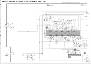
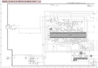
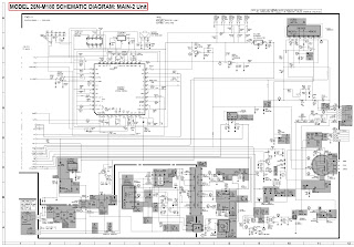
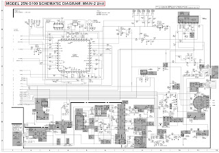
Sharp CTV - 25N-M100/180, 25N-S100/180, CN25M10, CN25S18, CN25S20 – SN91 Chassis – how to enter the service mode, adjustment procedure in detail, default data values


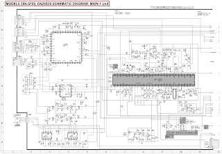
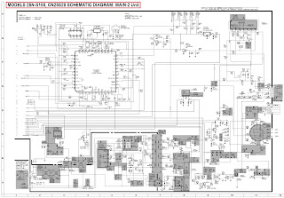
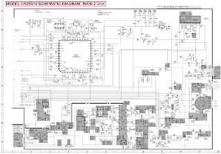
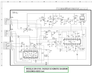
Sharp 25NM100, Sharp 25NS100 - service mode adjustments, schematic (full)
When performing any adjustments to resistor controls and transformers use non-metallic screwdrivers or TV alignment tools.   Before performing adjustments, the TV set must be on at least 15 minutes.
Circuit protection
The receiver is protected by a 4.0A fuse (F701), mounted on PWB-A, wired into one side of the AC line input.
After service has been performed on the horizontal deflection system, high voltage system, B+ system, test the X-Radiation protection circuit to ascertain proper operation as follows:
Apply 120V AC using a variac transformer for accurate input voltage.
2. Allow for warm up and adjust all customer controls for normal picture and sound.
3. Receive a good local channel.
4. Connect a digital voltmeter to TP653 and make sure that the voltmeter reads 11.2 ±0.6V.
5. Apply external 13.8V DC at TP653 by using an external DC supply, TV must shut off.
6. To reset the protector, unplug the AC cord and make a short circuit between TP651 and TP652. Now make sure that normal picture appears on the screen.
7. If the operation of the horizontal oscillator does not stop in step 5, the circuit must be repaired before the set is returned to the customer.
High voltage is not adjustable but must be checked to verify that the receiver is operating within safe and efficient design limitations as specified checks should be as follows:
Connect an accurate high voltage meter between ground and anode of picture tube.
2. Operate receiver for at least 15 minutes at 120V AC line voltage, with a strong air signal or a properly tuned in test signal.
3. Enter the service mode and select the service adjustment "S19" and Bus data "01" (Y-mute on).
4. The voltage should be approximately, 28.7kV (at zero beam).
If a correct reading cannot be obtained, check circuitry for malfunctioning components. After the voltage test, make Y-mute off to the normal mode.
For adjustments of this model, the bus data is converted to various analog signals by the D/A converter circuit.
[There are still a few analog adjustments in this series such as focus and master screen voltage.  Follow the steps below whenever the service adjustment is required. See "Table-B" to determine, if service adjustments are required.]
Service mode
Before putting unit into the service mode, check that customer adjustments are in the normal mode. Use the reset function in the video adjustment menu to ensure customer controls are in their proper (reset) position.
To enter the service mode and exit service mode.
While pressing the Vol-up and Ch-up buttons at the sametime, plug the AC cord into a wall socket.
Now the TV set is switched on and enters the service mode.
To exit the service mode, turn the television off by pressing the power button.
Service number selection
Once in the service mode, press the Ch-up or Chdown button on the remote controller or at the set.
The service adjustment number will vary in increments of one, from "S01" to "OP2" (25N-M100/ 180, CN25M10), "S01" to "M05"(25N-S100/180, CN25S18/20).
Select the item you wish to adjust.
Data number selection
Press the Vol-up or down button to adjust the data number.
Default data values
VCO Adjustment
1. Connect a digital voltmeter between pin (44) of IC201 and ground.
2. Receive a good local channel.
3. Enter the service mode and select the service adjustment "S10".
4. Adjust the data so that digital voltmeter reads 2.2V.
5. Adjustment is completed, remove the voltmeter, return to "normal" mode.
RF AGC Adjustment
1. Receive a good local channel.
2. Enter the service mode and select the service adjustment "S08".
3. Set the data value to point where no noise or beat appears.
4. Select another channel to confirm that no noise or beat appears.   You will have to come out of the service mode to select another channel.  Setting the data to "00" will produce a black raster.
Screen Adjustment
1. Connect a oscilloscope between TP854 and GND on the CRT Unit.
2. Receive a good local channel.
3. Enter the service mode and select the service adjustment "S03" and set the data value to "00" to set the color level to minimum. (Record original data code under adjustment "S03" before changing) You may skip this step, if you selected a B/W picture or monoscope pattern.
4. Select the service adjustment "S19" and adjust the data value to "01", this turn off the luminance signal (Y-mute).
5. Select the service adjustment "S04" and adjust data value to obtain 2.35 volts on the oscilloscope screen.
6. Adjust the master screen control until the raster darkens to the point where raster is barely seen.
7. Adjust the service adjustments "S11" red, "S12" green and "S13" blue to obtain a good grey scale with normal whites at low brightness level.
8. Select the service adjustment "S19" and reset data to "00". Select the service adjustment "S03" and reset data to obtain normal color level.
9. Remove oscilloscope, and reset the master screen control to obtain normal brightness range.
White Balance Adjustment
1. Receive a good local channel.
2. Enter the service mode and select the service adjustment "S03" and set to "00" (minimum color)(Record original data code under adjustment "S03" before changing). "S03" does not have to be adjusted, if you selected a B/W picture or monoscope pattern.
3. Alternately adjust service adjustment data of "S14" and "S15" until a good grey scale with normal whites is obtained.
4. Select the service adjustment "S03" and adjust data to obtain normal color level.
Sub-Picture Adjustment
1. Receive a good local channel.
2. Make sure the customer picture control is set to maximum.
3. Enter the service mode and select the service adjustment "S01".
4. Adjust the data value to achieve normal contrast range.
Sub-Tint Adjustment
1. Receive a good local channel.
2. Set customer tint control to center of it's range.
3. Enter the service mode and select the service adjustment "S02".
4. Adjust "S02" data value to obtain normal flesh tones.
Vertical-Size Adjustments
1. Receive a good local channel.
2. Enter the service mode and select the service adjustment "S09".
3. While observing the top and bottom of the screen, adjust "S09" data value to proper vertical size.
Vertical Phase Adjustment
1. Enter the service mode and select the service adjustment "S06".
2. Adjust data value to "00".
Note: This must be set "00" when changed data retrace line will appear.
Horizontal Position Adjustment
1. Receive a good local channel.
2. Enter the service mode and select the service adjustment "S07".
3. Adjust "S07" data value so that picture is centered.
Caption Position Adjustment (Horizontal)
1. Receive a good local channel.
2. Enter the service mode and select the service adjustment "S18".
3. A black text box appears on the screen
4. Adjust "S18" data value so that text box is positioned in the center of the screen.
3.58MHz Trap Adjustment- NTSC
1. Receive a good local channel.
2. Enter the service mode and select the service adjustment "S16".
3. This is a two position adjustment, "00" is ON, "01" is OFF.
4. Models should be adjusted as follows.
Sharpness and Audio Balance Adjustments
1. Receive a good local channel.
2. Enter the service mode and select the service adjustments "S05" for sharpness and "S17" for balance.
» Sharpness adjustment
3. Adjust data value to "28"(center of data range) for sharpness adjustment.
» Audio balance adjustment
4. Adjust data value to "20"(center of data range) for Audio balance adjustment.
Energy save offset Adjustment
1. Enter the service mode and select the service adjustment "S20".
2. Adjust data value to "23".
Note : This position is used to preset the level for the energy save function.
Other Adjustments
1. Enter the service mode.
2. Adjust the following data values as listed below.
MTS ADJUSTMENT - (Only for 25N-S100/180, CN25S18/20)
MTS Level Adjustment
1. Feed the following monaural signal to pin (14) of IC3001.  Monaural signal : 300Hz, 245mVrms
2. Connect the rms voltmeter to pin (39) of IC3001.
3. Enter the service mode and select the service adjustment "M01".
4. Adjust the data so that the rms voltmeter reads. 490 ±10mVrms.
MTS VCO Adjustment
1. Keep the unit in no-signal state.
2. Connect the frequency counter to pin (39) of IC3001.
3. Connect a capacitor (100µF, 50V) in between positive(+) side of C3005 and ground.
4. Enter the service mode and select the service adjustment "M02"
5. Adjust the data so that the frequency counter reads. 62.94 ±0.75kHz.
Filter Adjustment
1. Feed the following stereo pilot signal to pin (14) of IC3001 .
Stereo pilot signal: 9.4kHz, 600mVrms.
2. Enter the service mode and select the service adjustment "M03".
3. Adjust the data at the point where "OK" appears on the screen. The "OK" represents the approximate center of the adjustable range of the data.
Separation Adjustment
1. Connect the rms voltmeter to pin (39) of IC3001.
2. Receive the following composite stereo signal 1.
Composite stereo signal: 30% modulation, left channel only, noise reduction on, 300Hz
3. Enter the service mode and select the service adjustment "M04".
4. Adjust the data until the AC voltage reading of the rms voltmeter is minimum.
5. Receive the following composite stereo signal 2.
Stereo signal: 30% modulation, left channel only, noise reduction on, 3kHz
6. Enter the service mode and select the service adjustment "M05".
7. Adjust the data until the AC voltage reading of the rms voltmeter is minimum.
8. Take the above steps 1 thru 8 again for fine adjustment.
Schematic

Tuesday, January 28, 2020

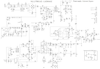
TCL L37M61AZ - L42M64AZ LCD TV Alignment Procedure - Power supply - Schematic Diagram - SMPS troubleshooting


How to troubleshoot the power board of TCL L37M61 and TCL L42M64 LCD TVs
Alignment Procedure – Service mode: 
To enter the factory mode
1.press the vol.- botton to 0 , enter the “picture” menu, cursor place the “ contrast”, input the digits 9735.
2. When using,  the heat key to open the factory menu , press the Freeze key if it is not the menu .
Factory menu white balance adjust and HDMI signal source inspection.
It is only adjusting white balance of the HDMI signal source Adjustment in HDMI mode.
1. Input HDMI signal: timing is 720P, Patter is 10 grey.
2. enter the factory menu, select white balance item, press OK key , system auto covering to HDMI signal source, and so on setting the color temperature item is standard 3. adjusting the white balance machine ,setting the color coordinate to adjust the color temperature
4. press OK key to auto adjusting, until cuing is finishing.
5. Looking into the fugue and screen menu , estimating screen menu or not in gear, exit the factory menu and inspecting the HDMI signal source.
Accessory 1: all the displaying item signification.
X/y: about standard color temperature of the color coordinate, it is manual setting before adjusting the white balance.
Manual adjustment mode.
The cursor placed to x or y, press “OK” key to enter manual adjustment of the white balance.
(2) The ADC in the factory menu is been adjusted and inspecting YpbPr /VGA/AV signal source only auto adjusting the YpbPr/VGA/AV signal source ,all signal source adjustment mode as  follows:
1.YpbPr
a. switching to YpbPr signal source ,input the
720@60 contrast of 100% eight grey-scale/color –bar signal reference machine model: timing81 of bsg360a, pattern85
b. enter the ADC of the factory menu item press OK key to auto adjusting
c. after cuing auto adjustment successfully, observing displaying figure and screen menu or not in gear, exit the factory menu and inspect the YpbPr signal source.
2.VGA
a. Switching to VGA signal source , input
1024x768@60Hz 16 grey or 10 grey reference machine model: BSG360A of Timing13,pattern105
b. Enter the factory menu ADC item, press OK key for auto adjusting.
c. after cuing auto adjustment successfully, observing successfully, observing displaying fugue and screen menu or not in gear, exit the factory menu and inspect the VGA signal source.
3.AV
d. Switching to AV signal source , input PAL
100% saturation of the 8 grey signal source reference machine model: BSG360A of Timing,pattern 85
e. enter the factory menu ADC item ,press OK key to auto adjusting.
f. after cuing auto adjustment successfully, observing successfully, observing displaying figure and screen menu or not in gear, exit the factory menu and inspect the AV signal source.
4 Inspect ATV/DTV signal source parting switch to ATV or DTV , and then scanningobserving or not losing channel and the picture displaying and volume in gear or not.
5 T
he factory menu function setting.
1) according to so you saying item: enactment LCD panel factory appellation, factory menu heat key setting to OFF, hotel mode setting to off; Electrify mode setting to STB.
2) select factory init item, press OK key to initialization operating about boot-strap
WARNING: during finishing the Factory init operating to packing , if the TV has been boot-strapped , the TV must operate again before packing.
SMPS schematic: Standby circuit working.
When switching on ,at first the standby circuit work. Supply 5V to the figure board , the main power start working when receiving the figure board boot-strap signal. Output: 24v 12v 300v volts d.c. pass the D810 R832 and then transformer(T803) primary coil there into 3 pin connect pin 5 6 7 of U4 VDD from U4 source drain put through and so that the transformer(T803) primary coil put through  telepathy secondary 9 pin outputting through D807 commute 5V
Standby voltage R838 sampling 5v voltage connect sampling 5V connect to pin 1 TLHPC92 therepathy U3 pin 3 4 put through  leave each other Connect from the signal to U4 PIN 3 4 control U4 outputting  and so that the transformer output the steady 5v.
At the same time the transformer T803 primary coil 4 pin divide into two-way outputting.
1 one-way output 15v to the VCC supply to IC supplying power.
2
one-way output to U4 supply power.
Switch - On work flow.
It passes R842 R841 D819 when receiving the figure board outputting the switch on high level signal  and then send to Q808 Base Q808 break over  TLU2 -1 2 pin break over the signal coupling to TL U2 pin 3 4.  At the same time Q807 cut off TLU2 pin 1 - 2 disconnection not coupling the signal to TLU2 pin 3 4. At the same time Q807 cut off 15V cannot supply through the Q807 outputting the VCC U5 and U6 stop working if they cannot receive the supply power.
PFC circuit.
15V ingress and U6 startup,P7 OUTPUT CONTROLLING Q801 CUT OFF AND BREAK OVER L801 is energy storage constantly commute the voltage Upgrade the 380V or not , pass the C807 filter, outputting to PWM circuit.
PWM circuit
After 15v enter u5 pin P6, U5 start working, p5 output the pulse signal control Q805 and Q802 base when the pulse signal is high level,Q805 cut off Q803 break over VCC pass though the Q802 and R813 to charge up C820. when the pulse signal is low level,Q805 break over Q803 cut off C802 pass though Q820 discharge . on account of C820 overlap cycle charge and discharge on account of T802 secondary coil coupling to signal variety,and so that control Q803 AND Q806 cut off and disconnect. In this way PFC Circuit output voltage connecting the transform T801 primary coil also repeat constantly deposited entry and released energy exchange course , and then telepathy to secondary coil and output voltage: 12v 24v 12V and 24V steady circuit. Pass through R811 sampling 24v and R808 sampling 12v,sampling the signal passing through U1 telepathy controlling U5 PIN P2 ,adjust U5 PIN P5 Output the pulse width adjust T801 output.
Overvoltage protect: When the voltage is over and sampling signal mix through D809 R856 , the high level send to Q812 base at the same time Q810 collector is high level.
Q810 is break over through D820 connect to R842 the potential alter low level  the switch on signal high level can not operate TV starts standby.
Low-voltage protect: When it is in gear about 24v , 24v through R1004 R1005 R1006 change the voltage the Q1001 break-over Q1001 collector is lower level.
When the voltage is lower 24v, D1002 cannot break –over Q1001 collector is high level ,D1001 and Q812 break-over switch-on signal voltage change lower, TV shift standby.
SMPS schematic
SMPS troubleshooting procedure
SMPS faults: No voltage
Analysis and detect: at first testing the switching on
 p802 gain 2.2v switching on voltage in power board, constant the power is on testing 12v and 24v is 0v measuring 5v is in gear. Showing the TV can standby in gear. If measuring 12v and 24v is 0V the problem cause is 12v and 24v commonality part.
12v and 24v commonality part is  PFC part and power PWN part  over current and voltage protect part. At first measure L809 PFC voltage.  If it discovering 380v is 0V the problem is PFC contact the PWM problem , primary analyzing cause is 15V circuit U5 and U6 can not work when only 15V has not in gear.
We know: the transformer T803 secondary coil 4 pin output second part:
1. one way output 15V to VCC
supply to ic power supply
2. one way to U4 supply power
supply to 5VSTB
because 5V is in gear IC power supply is 15V measure R826 VCC outputting voltage is 0V. measure R826 resistance to GND is in gear. And then measuring Q807 transmit is not voltage. Measure D824 discovering one pin has voltage  measure D824  discover the D824 disconnection replace the D824 the voltage is ok.
No voltage
Analysis and detect: at first testing the switching on
p802 gain 2.2v switching on voltage in power board, constant the power is on testing 12v and 24v is 0v measuring 5v is in gear. Showing the TV can standby in gear. Measuring 12v and 24v is 0V, the problem cause is 12v and 24v commonality part.
12v and 24v commonality part is PFC part and power PWN part  over current and voltage protect part. At first is there 15V of VCC Is there Q807 Transistor of 13V.  U2 has not gain the switch on controlling signal.  Disconnect D820 and than measure  now avoid the problem of over current and voltage  the problem is the switch on signal has not effect. Constant switch on signal has inputted the P802 testing discover R842 disconnection the Switch on signal has not send to the Q808 replace R842 The TV switch on testing the fault avoid.
No voltage
Analysis and detect: at first testing the switching on
p802 gain 2.2v switching on voltage in power board, constant the power is on testing 12v and 24v is 0v measuring 5v is in gear.  Showing the TV can standby in gear. If measuring 12v and 24v is 0V the problem cause is 12v and 24v commonality part.
12v and 24v commonality part is PFC part and power PWN part  over current and voltage protect part.
At first disconnect D820  affirm where the problem is part  and then measure 13V of VCC  if it is in gear continue testing PFC voltage is in gear
So that determinant the problem is protect circuit measuring D820 cathode to GND resistance discovery resistance is littler than in gear  testing Protect circuit discovery Q812 short circuit attain. Replacing the Q812 ,the TV is ok.
Switch on voltage moment 12V testing point is 20V 24V testing point is 30V. fall to 0.4V or not moment .
Analysis and detect: at first testing the switching on
p802 gain 2.2v switching on voltage in power board, constant the power is on switch on voltage moment 12V testing point is 20V,24V testing point is 30V. fall to 0.4V or not moment .measuring 5V is in gear the TV can standby in gear the problem is 12V and 24V steadfast voltage pass from R811 sampling 24V and R808 sampling 12V sampling signal pass though telepathy controlling U5 pin P5, and then output the pulse width adjust T801 outputting.
Detecting 12V and 24V steadfast voltage part discovering Q804 is bad, replace it the fault rectified.
When5V, dithering, and the output is 4V, no voltage at 12 V and 24V
Analysis, examine and repair: Open the panel and test, find out when 5V, dithering, the output is 4V, and no output at other voltage, it means there is something wrong with standby, it can’t export the stable 5V standby voltage.
At first, Check whether the commute bridge exports voltage: measure and find out there is 300 V direct current in D810, then check U4 to find out whether it starts work, measure the start voltage of U4 at first. There is dithering in 11V, but 13V is normal, the matter is in support part of work voltage, measure pin 4 voltage output of D803,there has voltage, measure D822, it is no voltage, then measure R847, find out there is plough, exchange it and eliminates the malfunction.
No voltage at 5V, 12 V and 24V.
Analysis, examine and repair: open the panel and test, there is no voltage, means the machine has something wrong with standby, it can’t output the 5V standby voltage, so it can’t produce 12V and 24V.
Check whether the commute bridge exports voltage: measure and find out there is 300V direct current in D810,then check U4 to find out whether it starts work,
measure the start voltage of U4 at first. There is dithering in 6-7V, but 13V is normal, measure 4 feet voltage output of D803, there has voltage, measure D822, it is
7V, find out no output when test D824,shows that it can’t run normally when at 5V , so exchange the U4, malfunction disappears.
No voltage for 12V and 14V.
Analysis, examine and repair: open the machine and test at first, find out when standby at 5V voltage is normal means no problem with standby, provide the 2.2V start voltage, no voltage output, so there is something wrong with the 12V and 14V voltage part, maybe the problem appears in PFC, PWM and protective circuit.
Measure the output voltage of VCC, 12V in R836, at this time there is noise in transformer, it is the voltage output reducing, maybe there is something wrong with the protective circuit, then cut D820 of protective circuit, test again, there is normal voltage output, so it can conclude that the problem is in protective circuit, the problem is over current and voltage or low-voltage
low-current protect circuit Cut the protect point after connect the D820, voltage goes back to normal when cuts the D1001, then test the low-voltage protect circuit , Q1001 is plough, exchange it and the malfunction disappears.
The TV has no power
Analysis, examine and repair: check the machine first, find out the fuse is cut and no obvious component burned-out mark, circuitry has over current or voltage circuit since the fuse is burned, means there is short circuit in somewhere. Measure and find out the Q801 has been short circuit, no short circuit finding in other parts, exchange the Q801, test against, 5V voltage is normal, but no output at 12V - 24V, because the PFC is broken, the voltage output of PFC is only about 320V, PFC doesn’t run, the power supply voltage of PFC at 14V, it is normal, so decide to exchange U6, the malfunction is still here, measure each feet against floor resistance of U6 in turn, find out the R869 is plough, exchange and test, eliminates malfunction, the fact is that R869 disconnect caused the U6 over current protect circuit runs U6 stop the output, so there is no voltage output of PFC, and no voltage.
No voltage for 12V and 14V.
Analysis, examine and repair: open the panel and test at first, find out when standby at 5 V, the voltage is normal, means no problem with standby, then provide 2.2 V start voltage, make out no output at12V and 14V. The TV is standby.
Problem both at 12V and 14V voltage, maybe there is some matter with PFC, PWM and protective circuit, so measure output of PFC first, it is 320V, means PFC doesn’t work, cut down the protective circuit, start the machine to test the output on 12V and 14V voltage, it is normal, so the problem appears in protective circuit, cut down the over current protect point separately to test , malfunction still, then cut down the exceed press protect, malfunction still,too, cut down the low-voltage protect Q1001 at last, malfunction disappears, and none of
base voltage with Q1001, test and find out that 24V low-voltage protect sampling resistance R1004 disconnection. Open the machine after exchange it, malfunction disappears.
No voltage for 12V and 14V.
Analysis, examine and repair: open the panel and test at first, find out when standby at 5 V, the voltage is normal, means no problem with standby, then provide 2.2 V start voltage, make out no output at 12V and 14V. The machine is standby, problem appears both at 12V and 14V voltage, maybe there is some matter with PFC, PWM and protective circuit, so measure output of PFC first, if is 380 V, means PFC runs normally. It can conclude that problem is at 12V and 14V voltage part.
Since no voltage for both at 12V and 14V, the chance that feedback loop gets in trouble is not big, check the PWM circuit first, examine the going of U5, check whether there is drive voltage of pin P5 on U5,dittering on 1.5V more or less is normal. Then measure against floor resistance of P5 on U5, cut down the outing circuit, short circuit, it can conclude that U5 has been broken, open after exchange it, find out that the malfunction disappears.

Tuesday, January 21, 2020

AV RECEIVER Yamaha RX-V767/HTR-7063, RX-A800 – software update, service adjustment, initialization, Idle current adjustment


How to update the firmware, how to enter service mode, service mode adjustments - Yamaha AV Receiver RX V767, Yamaha RX A800
Updating firmware
When the following parts are replaced, the firmware must be updated to the latest version.
DIGITAL P.C.B.
IC951 (TI (DSP) flash ROM) of DIGITAL P.C.B
Confirmation of firmware version and checksum
Before and after updating the firmware, check the firmware version and checksum by using the self diagnostic function menu.
Start up the self-diagnostic function and select “S4.
ROM VER/SUM” menu.
Using the sub-menu, have the firmware version and checksum displayed, and note them down.
* When the firmware version is different from written one after updating, perform the updating procedure again from the beginning.
Initializing the back-up IC
(EEPROM: IC903 of the DIGITAL P.C.B.)
After updating the firmware, the back-up IC MUST be initialized by the following procedure to have proper memorization of the set up information (sound field parameters, system memory and tuner presetting, etc.).
Start up the self-diagnostic function and select “S3.
FACTORY PRESET” menu. (See “SELF-DIAGNOSTIC FUNCTION”)
Select “PRESET RSRV”, press the “MAIN ZONE ” (power) key of this unit to turn off the power once and turn on the power again. Then the back-up IC is initialized.
Required Tools
• BD, DVD or CD player (with DIGITAL OUTPUT (OPTICAL or COAXIAL) jack)
• Optical cable (when OPTICAL jack is used)
• Digital audio pin cable (when COAXIAL jack is used)
• Firmware CD
* Download the latest firmware from the specified download source and create the firmware CD.
Operation Procedures
1. While pressing the “TUNING >>” key of this unit, connect the power cable of this unit to the AC outlet.
The FIRMWARE UPDATE mode is activated and “CDDA Upgrader” is displayed.
2. Play the firmware CD on the BD/DVD/CD player. Writing of the firmware starts automatically.
3. When writing of the firmware is completed, “Update Success”, “Please...” and “Power off!!” are displayed repeatedly.
* If the display remains unchanged for more than 10 seconds after starting the firmware CD play procedure, perform the firmware CD play procedure again from the beginning.
If “FILE CORRUPTED” is displayed after “Address:XXXXXX”, make sure that the written data is not corrupted and perform Steps 1 to 3 of “Operation Procedures” again.
If “Upgrade Failed” is displayed, perform "operation procedures" again from the beginning.
4. Press the “MAIN ZONE ” (power) key of this unit to turn off the power.
5. Eject the firmware CD from the BD/DVD/CD player.
6. Start up the self-diagnostic function and check that the firmware version and checksum are the same as written ones. (See “Confirmation of firmware version and checksum”)
Self-diagnostic function
This unit has self-diagnostic functions that are intended for inspection, measurement and location of faulty point.
There are 24 main menu items, each of which has submenu items.
Starting Self-Diagnostic Function.
While pressing the “TONE CONTROL” and “INFO” keys of this unit as shown in the figure below, press the “MAIN ZONE ”(power) key of this unit to turn on the power.
The self-diagnostic function mode is activated.
Starting Self-Diagnostic Function in the protection cancel mode
If the protection function works and causes hindrance to trouble shoot, cancel the protection function as described below, and it will be possible to enter the self-diagnostic function mode.
(The protection functions other than the excess current detect function will be disabled.)
While pressing the “TONE CONTROL” and “INFO” keys press the “MAIN ZONE ” (power) key to turn on the power and keep pressing those 2 keys for 3 seconds or longer.
The self-diagnostic function mode is activated with the protection functions disabled.
In this mode, the “SLEEP” segment of the FL display of this unit flashes to indicate that the mode is self-diagnostic function mode with the protection functions disabled.
CAUTION
Using this product with the protection function disabled may cause further damage to this unit. Use special care for this point when using this mode.
Canceling Self-Diagnostic Function
Before canceling self-diagnostic function, execute setting for FACTORY PRESET of main menu No. S3. (Memory initialization inhibited or Memory initialized).
* In order to keep the user memory preserved, be sure to select PRESET INHIBIT (Memory initialization inhibited).
2. Press the “MAIN ZONE ” (power) key of this unit to turn off the power
Display provided when Self-Diagnostic Function started
The display is as described below depending on the situation the last time the power to this unit is turned off.
1. When the power is turned off by usual operation:
The FL display of this unit displays “NO PROTECT” then the main menu (sub-menu “A1-1. DSP MARGIN” of main menu No. A1 DSP AUDIO) a few seconds later.
When the protection function worked to turn off the power:
The FL display of this unit displays the data of protection function which worked at that time then the main menu (sub-menu “A1-1. DSP MARGIN” of main menu No. A1 DSP AUDIO) a few seconds later.
Note: At that time if you reactivate the self-diagnostic function after turning off the power once by pressing the “MAIN ZONE ” (power) key, “NO PROTECT” will be displayed because that situation is equal to “1. When the power is turned off by usual operation:” described above.
However the protection function history is stored in a back-up IC with a backup. For details, refer to main menu P2 PROTECTION HISTORY.”
When there is a history of protection function due to excess current.

An excessive current flowed through the power amplifier.
Supplementary information: As current of the power amplifier is detected, the abnormal channel can be identified by checking the current detect transistor.
Turning on the power without correcting the abnormality will cause the protection function to work immediately and the power supply will instantly be shut off.
Notes
• Applying the power to this unit without correcting the abnormality can be dangerous and cause additional circuit damage. To avoid this, if “I PROTECT” protection function works 1 time, the power will not turn on even when the “MAIN ZONE ” (power) key is pressed. In order to turn on the power again, start up the self-diagnostic function.
• The output transistors in each amplifier channel should be checked for damage before applying power to this unit.
• Amplifier current should be monitored by measuring DC voltage across the emitter resistors for each channel.
 When the protection function worked due to abnormal DC output.
DC output of the power amplifier is abnormal.
Supplementary information: The protection function worked due to a DC voltage appearing at the speaker terminal. A cause could be a defect in the amplifier.
Turning on the power without correcting the abnormality will cause the protection function to work in 3 seconds and the power supply will be shut off.
When the protection function worked due to abnormal voltage in the power supply section.
The voltage in the power supply section is abnormal.
Supplementary information: The protection function worked due to a defect or overload in the power supply.
Turning on the power without correcting the abnormality will cause the protection function to work in 1 seconds and the power supply will be shut off.
Notes)
• Applying the power to this unit without correcting the abnormality can be dangerous and cause additional circuit damage. To avoid this, if “PS” and “DC” protection function works 3 times consecutively, the power will not turn on even when the “MAIN ZONE ” (power) key is pressed.
In order to turn on the power again, start up the self-diagnostic function.
• The output transistors in each amplifier channel should be checked for damage before applying power to this unit.
• Amplifier current should be monitored by measuring DC voltage across the emitter resistors for each channel.
When the protection function worked due to excessive heat sink temperature.
The temperature of the heat sink is excessive.
Supplementary information: The protection function worked due to the temperature limit being exceeded.
Causes could be poor ventilation or a defect related to the thermal sensor.
Turning on the power without correcting the abnormality will cause the protection function to work in 1 seconds and the power supply will be shut off.
History of protection function
When the protection function has worked, its history is stored in memory with a backup.
Even if no abnormality is noted while servicing the unit, an abnormality which has occurred previously can be defined as long as the backup data has been stored..
Initial settings used to start Self Diagnostic Function
The following initial settings are used when starting self diagnostic function.
When self-diagnostic function is canceled, these settings are restored to those before starting self-diagnostic function.
• Master volume: -20 dB / Zone volume: +2.5dB
• Input: HDMI1 / Zone: AUDIO1
• Main menu: A1-1. DSP MARGIN
• Speaker setting: LARGE, Bass out to SWFR (All channels)
• HDMI Control: Off
• Zone: On
Details of Self-Diagnostic Function menu
DSP AUDIO
This menu is used to check audio signal route via DSP.
A1-1. DSP MARGIN
The audio signal is output including the head margin via DSP.
* When input source is stereo, signal is assigned as below.
Front L: Front L, Center, Surround L,
Surround Back L
Front R: Front R, Surround R,
Surround Back R
Front L +10 dB: Subwoofer.
DSP NON MARGIN
The SUBWOOFER signal is output including the head margin via DSP.
The audio signal other than SUBWOOFER is output without including the head margin via DSP
CONFIRMATION OF IDLING CURRENT OF AMP UNIT
Right after power is turned on, confirm that the voltage across the terminals of R1152 (SURROUND BACK Rch), R1154 (SURROUND Rch), R1150 (FRONT Rch), R1148 (CENTER), R1149 (FRONT Lch), R1153 (SURROUND Lch), R1151 (SURROUND BACK Lch) are between 0.1mV and 10.0mV.
● If it exceeds 10.0 mV, open (cut off) R1090 (SURROUND BACK Rch), R1092 (SURROUND Rch), R1088 (FRONT Rch), R1086 (CENTER), R1087 (FRONT Lch), R1091 (SURROUND Lch), R1089 (SURROUND BACK Lch) and reconfirm the voltage.
Attention
If the measured voltage exceeds 10.0mV after an amplifier repair, first check for a defective component before cutting the bias resistor.
● Confirm that the voltage is 0.2 mV to 15.0 mV after 60 minutes.