Wednesday, July 15, 2020

Panasonic TX L42B6E, Panasonic TX L42B6ES KM21E Chassis LCD TV Service mode, adjustments, Option bytes, Error codes, Voltages and more

How to enter the service mode Panasonic TXL42BX6E, adjustments, error codes, LED blinking codes, data copy, service tool kit, option bytes, Power board circuit diagram
Service Mode Function
MPU controls the functions switching for each IICs through IIC bus in this chassis. The following setting and adjustment can be adjusted by remote control in Service Menu
How to enter into Service Mode
While pressing [VOLUME ( - )] button on the main unit, press the [RED] button on the remote control for 3 times within 2 seconds.
How to exit
Switch off the power with the [POWER] button on the main unit or the [POWER] button on the remote control.
Service key commands
Press the 3/4 button to change the adjustment values or function.
Press the 1/2 button to step up/down through the functions and adjustments
Press the numerical button VOLUME (+/-) to change of each option item.
Press the OK button after each adjustment has been made to store the required values.

Chassis Board Layout
Setting Inspection: Voltage Confirmation
Service Tool Mode
1. Select [SRV-TOOL] in Service Mode.
2. Press [OK] button on the remote control.
Service mode flow chart
Display of SOS History
SOS History (Number of LED blinking) indication.
From left side; Last SOS, before Last, three occurrence before, 2nd occurrence after shipment, 1st occurrence after shipment.
This indication will be cleared by [Self/check indication and forced to factory shipment setting].
Power ON Time, On/Off
Note: To display TIME/COUNT menu, highlight position, then press MUTE for 3sec.
Time: Cumulative power on time, indicated hour: minute by decimal.
On/Off: Number of On/Off switching by decimal.
Note: This indication will not be cleared by either of the self-checks or any other command.
Exit
Disconnect the AC cord from wall outlet or switch off the power with [Power] button on the main unit.

Hotel Mode
1. Purpose
Restrict a function for hotels.
2. Access command to the Hotel mode setup menu.
In order to display the Hotel mode setup menu,
please enter the following command (within 2 second).
[TV] : Vol.[Down] + [REMOTE] : AV (3 times)
Then, the Hotel mode setup menu is displayed.
3. To exit the “Hotel mode”:  Switch off the power with the [POWER] button
on the main unit or the [POWER] button
on the remote control.
4. Explain the Hotel mode setup menu.

Data Copy by USB Memory
Purpose
a) Board replacement (Copy the data when exchanging A-board):
When exchanging A-board, the data in original A-board can be copied to USB Memory and then copy to new A-board.
Following data can be copied.
User setting data
(inc. Hotel mode setting data)
Channel scan data
Adjustment and factory preset data.
b) Hotel (Copy the data when installing a number of units in hotel or any facility):
When installing a number of units in hotel or any facility, the data in master TV can be copied to USB Memory and the copy to other TVs.
Following data can be copied.
User setting data
(inc. Hotel mode setting data)
Channel scan data.
Preparation
Make pwd file as startup file for (a) or (b) in an empty USB Memory.
1. Insert an empty USB Memory to your PC.
2. Right-click a blank area in a USB Memory window, point to New, and then click text document. A new file is created by default (New Text Document.txt).
3. Right-click the new text document that you just created and select rename, and then change the name and extension of the file to the following file name (a) or (b) and press ENTER.
File name:
(a) For Board replacement: boardreplace.pwd
(b) For Hotel: hotel.pwd
Note:
Please make only one file to prevent the operation error.
No any other file should be in USB Memory.
Data Copy from TV set to USB Memory
1. Turn on the TV set.
2. Insert USB Memory with a startup file (pwd file) to USB Terminal.  On-screen Display will be appeared according to the startup file automatically.
3. Input a following password for (a) or (b) by using remote control.
(a) For Board replacement: 2770
(b) For Hotel: 4850
Data will be copied from TV set to USB Memory.
It takes around 2 to 6 minutes maximum for copying.
4. After the completion of copying to USB Memory, remove USB Memory from TV set.
5. Turn off the TV set.
Note:
Following new folder will be created in USB Memory for data from TV set.
(a) For Board replacement: user setup
(b) For Hotel: hotel.
Data Copy from USB Memory to TV set
1. Turn on the TV set.
2. Insert USB Memory with Data to USB Terminal.  On-screen Display will be appeared according to the Data folder automatically.
3. Input a following password for (a) or (b) by using remote control.
(a) For Board replacement: 2771
(b) For Hotel: 4851
Data will be copied from USB Memory to TV set.
4. After the completion of copying to USB Memory, remove USB Memory from TV set.
(a) For Board replacement: Data will be deleted after copying (Limited one copy).
(b) For Hotel: Data will not be deleted and can be used for other TVs.
5. Turn off the TV set.

Note:
1. Depending on the failure of boards, function of Data for board replacement does not work.
2. This function can be effective among the same model numbers.
Option Bytes Description
Self Check:  Self-check indication only:
While pressing [VOLUME ( - )] button on the main unit, press [OK] button on the remote control.

Self-check indication and forced to factory shipment setting:
While pressing [VOLUME ( - )] button on the main unit, press [MENU] button on the remote control for more than 3 seconds.
How to exit
Switch off the power with the [POWER] button on the main unit.
If the CCU ports have been checked and found to be incorrect or not located then " - - " will appear in place of "O.K."
Power LED blinking timing chart
When abnormality has occurred the unit, the protection circuit operates and reset to the standby mode. At this time, the
defective block can be identified by number of blinking of the Power LED on the front panel of the unit.
LCD Panel Test Mode
To find the possible failure point where in LCD Panel or Printed Circuit Board when the abnormal picture is displayed.
How to Enter:
While pressing [VOLUME ( - )] button of the main unit, press [YELLOW] button of the remote control three times.
How to Exit:
Switch off the power with the [POWER] button on the main unit or the [POWER] button on the remote control.
How to confirm:
If the abnormal picture is displayed, go into LCD Panel test mode to display the several test patterns.
And then, judge by the following method.
Still abnormal picture is displayed: The cause must be in LCD Panel.
Normal picture is displayed: The cause must be in A board.
Remarks:
The test pattern is created by the circuit in LCD Panel.
In LCD Panel test mode, this test pattern is displayed unaffected by signal processing for RF or input signal.
If the normal picture is displayed, LCD Panel must be okay and the cause of failure must be in A board.
Adjustment Method: White Balance Adjustment
Power board schematic

Saturday, July 11, 2020

Harman kardon SUB TS11 Sub woofer Troubleshooting, schematic and alignments, wiring details

The Sub-TS11 subwoofer is part of the HKTS 11 system, included in the harman kardon HS300 system – Circuit diagram, test methods and wiring details, Exploded view

Satellite loudspeakers SAT-TS11 order hk part  HKTS 14-A SAT-E-P
Center channel CEN-TS11 order hk part  HKTS 7-A CEN-E –P

Amplifier Power (RMS):  200 Watts.

Driver:  10" (254mm) woofer, Bass Reflex Enclosure.

Inputs:  Stereo Line Level, dedicated .Subwoofer (LFE) and Speaker Level with gold-plated binding posts.

Outputs:  Speaker Level with gold-plated binding posts.

External Trigger Input Voltage:  3-30 Volts AC/DC.

Dimensions (H x W x D):  20-1/2" x 14-1/2" x 14-1/2" (521mm x 368mm x 368mm)

Weight:  48 lb (21.8kg)

Dolby® Digital or DTS® (or Other Digital Surround Mode) Connection Use this installation method for dolby digital, dts or other digital surround processors:

Use the line-level input jack marked SUB (6) for the low-frequency effects channel.
Connect this jack to the subwoofer output or LFE output on your receiver or amplifier.
Connect each speaker to the corresponding speaker terminals on your receiver or amplifier.

Make sure you’ve configured your surround sound processor for “Subwoofer On.” The front left, front right, center and surround speakers should all be set to “Small.”
When all connections have been made, plug the AC power cord on the subwoofer into an AC outlet.

Dolby Pro Logic® (Non-Digital) – Line Level

Use this installation method for dolby pro logic applications (not dolby digital, dts or other digital processing), where the receiver/processor is equipped with a subwoofer output, or a volume controlled preamp (line-) level output:
Use the supplied RCA-type interconnect cable to connect the line-level subwoofer output on your receiver or amplifier to either the left or right Line-Level Full-Range Input (7) on the SUB-TS11 subwoofer.
Use both the left and right inputs on the subwoofer if your receiver or processor has both left and right line-level outputs. In that case, you will need to supply a second interconnect cable.
If your receiver is equipped with line-level outputs but does not have a separate subwoofer output, use a Y-adapter (not supplied) to bridge the receiver’s preamp output to the main amp input for that channel, and connect the long end of the adapter to the corresponding line-level input on the SUB-TS11.
IMPORTANT: Do not use the SUB Input (6) on the subwoofer with Dolby Pro Logic processors.
If your receiver/processor has a built-in lowpass-crossover filter for the subwoofer output, you may use the SUB Input (6) to bypass the subwoofer’s internal crossover.
Connect each speaker to the corresponding speaker terminals on your receiver or amplifier.
Make sure that you have configured your surround sound processor for “Subwoofer On.” The front left, front right, center and surround speakers should all be set to “Small.”
When all connections have been made, plug the AC power cord on the subwoofer into an AC outlet.

Dolby Pro Logic (Non-Digital) – Speaker Level
Use this installation method for dolby pro logic applications (not dolby digital, dts or other digital processing), where the receiver/processor does not have a  subwoofer output, or a volumecontrolled preamp (line-) level output:
Connect your receiver or amplifier’s front left and right speaker terminals to the left and right Speaker-Level Input (9) terminals on the SUB-TS11 subwoofer that are marked “High Level In.” Connect the left and right Speaker-Level Output (8) terminals on the SUB-TS11 subwoofer that are marked “High Level Out” to the corresponding terminals on the back of your front left and right speakers.
Connect your receiver or amplifier’s center, and surround left and right speaker terminals to the corresponding terminals on the back of your center, and surround left and right speakers.
When all connections have been made, plug the AC power cord on the subwoofer into an AC outlet.

General Unit Function (UUT = Unit Under Test)

1) From the signal generator, connect one line level (RCA) cable to the Subwoofer Line Level Input jacks L/R on the UUT. Use a Y-cable from a mono source if necessary to connect to both inputs. Do not connect to the single, purple SUB input.
2) Turn on generator; adjust to 60mV, 50 Hz.
3) Plug in UUT; turn the power switch ON. Turn LEVEL control full clockwise (MAX)
4) LED should turn from Amber to Blue (on top of UUT); immediate and vigorous bass response should be heard and felt from port tube opening.
5) Turn off generator, turn LEVEL control full counterclockwise (MIN), and disconnect RCA cable.
6) Connect one pair of speaker cables to Speaker Level input terminal (IN) on UUT. Cables should be connected to an integrated amplifier fed by the signal generator.
7) Turn on generator and adjust so that speaker level input at the amplifier is 1.2V, 50 Hz. Turn LEVEL control full clockwise.
8) LED should turn from Amber to Blue; immediate and vigorous bass response should be heard and felt from the port tube opening.

Sweep Function.

1)Follow steps 6-8 above, using a sweep generator as a signal source.
2) Sweep generator from 20Hz to 300Hz. Listen to the cabinet and drivers for any rattles, clicks, buzzes or any other noises. If any unusual noises are heard, remove woofers and test.

Driver Function.

1) Remove woofer from cabinet; detach + and - wire clips.
2) Check DC resistance of woofer; it should be 2.8 ohms ±10%.
3) Connect a pair of speaker cables to driver terminals. Cables should be connected to an integrated amplifier fed by a signal generator. Turn on generator and adjust so that speaker level output is 5.0V.
4) Sweep generator from 20Hz to 1kHz. Listen to driver for any rubbing, buzzing, or other unusual noises.

Troubleshooting.

Printed circuit board and component layout.

Components description.

Schematic.

Exploded view.


Thursday, July 09, 2020

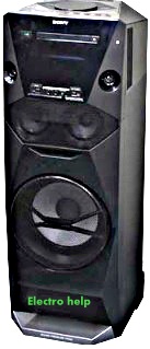
Sony MHC V6D – how to reset, service mode, service adjustments, main amplifier schematic, error codes

MHC V6D Sony hoe audio system, user reset, system reset, tuner step change, version display, power amplifier circuit diagram and more

DVD Mechanism Type:  CDM90-DVBU202 or CDM90-DVBU204

Optical Pick-up Block Name:  CMS-S76RFS7G or CMS-S76RFS7G1 or CMS-S76RFS7GP

COLD RESET
It can clears all data including preset data stored in the memory to initial conditions. Execute this mode when returning the this unit to the customer.

1. Press the [Power] button to turn the power on.
2. Press two buttons of the [
Stop] and [PAN] simultaneously for three seconds.
3. The message “COLD RESET” is displayed on the fluorescent indicator tube, then becomes the standby state.

USER RESET
It can clears all data including preset data stored in the memory to initial conditions (Only the connection history information of Bluetooth is not initialized).

1. Press the [Power] button to turn the power on.
2. Press two buttons of the [
Stop] and [BASS BAZUCA] simultaneously for three seconds.
3. The message “RESET” is displayed on the fluorescent indicator tube, then becomes the standby state.

AM TUNER STEP CHANGE
It can change AM step interval into 9 kHz or 10 kHz.

1. Press the [Power] button to turn the power on.
2. Press the [FUNCTION] button to turn the AM function.
3. Press the [
Power] button to turn the power off.
4. While pressing the [
|>> TUNING+] button, press the [Power] button.
5. The message “9K STEP” or “10K STEP” is displayed on the fluorescent indicator tube, and AM step interval changed.

DISC TRAY LOCK MODE
It can be unable to take sample disc out of disc tray in the shop

1. Press the [Power] button to turn the power on.
2. Press the [FUNCTION] button to turn the DVD/CD function.
3. Press the [
UP] button to open the disc tray and set the disc.
4. Press the [
UP] button to close the disc tray.
5. Press two buttons of the [
Stop] and [ENTER] simultaneously for three seconds.
6. The message “LOCKED” is displayed on the fluorescent indicator tube and the disc tray is locked.
(Even if pressing the [
UP] button, the message “LOCKED” is displayed on the fluorescent indicator tube and the disc tray is locked).

Releasing method:
1. Press two buttons of the [Stop] and [ENTER] simultaneously for three seconds.
2. The message “UNLOCKED” is displayed on the fluorescent indicator tube and the disc tray is unlocked.

Bluetooth PAIRING HISTORY CLEAR
It can clear the Bluetooth pairing history.

1. Press the [Power] button to turn the power on.
2. Press the [FUNCTION] button to turn the Bluetooth function.
3. Press two buttons of the [
Stop] and [FLANGER] simultaneously for three seconds.
4. The message “BT HISTORY” → “CLEAR” is displayed on the fluorescent indicator tube, and the pairing history of Bluetooth is cleared.

VERSION DISPLAY
It can confirm the SC and MTK version.

1. Press the [Power] button to turn the power on.
2. Press two buttons of the [ENTER] and [MOVIE/GAME] simultaneously for three seconds.
3. The SC and MTK version is displayed on the fluorescent indicator tube, and it returns to the display of the normal mode.

PANEL TEST
It can confirm the fluorescent indicator tube, LEDs, model name, destination, software version and button.

1. Press the [Power] button to turn the power on.
2. Press two buttons of the [ENTER] and [FOOTBALL] simultaneously for three seconds.
3. It enters the panel test mode, and all segments on the fluorescent indicator tube and all LEDs light up.

4. Each time the [ENTER] button is pressed; the screen display is changed in order as follows.


5. When pressing the [+PRESET+] button, the model name is displayed on the fluorescent indicator tube.

6. Each time [ +PRESET+] button is pressed, the display changes destination → SC version → MTK version → OPU version → UI version → PF version → SYS version → CD version → CMA version → CMB version → ST version → TA version → TM version this order, and returns to the model name display.


7. When pressing the [Stop] button while the each version is displayed, month and day of the software creation is displayed.  When pressing the [Stop] button again, the display returns to the each version display.

8. When pressing the [ –PRESET–] button, “K 0 V0” is displayed on the fluorescent indicator tube.

9. Each time a button is pressed, “K 0” value increases. However, once a button is pressed, it is no longer taken into account.
When pressing the all buttons, “K22” and “OK” are displayed alternately.

10. “V0” value increases “V1”, “V2”, “V3” · · · “V8”, “V9”, “V0” if turn the [VOLUME/DJ CONTROL] knob clockwise, or it decreases “V9”, “V8”, “V7” · · · “V2”, “V1”, “V0” if turn the knob counterclockwise.

Releasing method:
Press two buttons of the [ENTER] and [FOOTBALL] simultaneously for three seconds.

DVD COLOR SYSTEM CHANGE
It can change DVD color system into NTSC or PAL.

1. Press the [Power] button to turn the power on.
2. Press the [FUNCTION] button to turn the DVD/CD function.
3. Press two buttons of the [PAN] and [LED COLOR] simultaneously for three seconds.
4. The message “COLOR NTSC” or “COLOR PAL”is displayed on the fluorescent indicator tube, and DVD color system changed.

5. When the “NTSC” mark is lights up, DVD color system is NTSC.
When the “NTSC” mark is turns off, DVD color system is PAL.

5. When the “NTSC” mark is lights up, DVD color system is NTSC.  When the “NTSC” mark is turns off, DVD color system is PAL.

TEST DISC LIST
Be sure to use the DVD disc that matches the signal standards of your region.
For CD - Part No. Description

3-702-101-01
4-225-203-01
J-2501-307-A

DISC (YEDS-18), TEST
DISC (PATD-012), TEST
DISC (HLX-A1), TEST

For DVD SL (Single Layer)

Part No. Description

J-6090-069-A
J-6090-088-A
J-6090-077-A

DISC (HLX-503), TEST (NTSC)
DISC (HLX-504), TEST (NTSC)
DISC (HLX-506), TEST (PAL)

For DVD DL (Double Layer)
Part No. Description

J-6090-071-A
J-6090-089-A
J-6090-078-A

DISC (HLX-501), TEST (NTSC)
DISC (HLX-505), TEST (NTSC)
DISC (HLX-507), TEST (PAL)

Procedure to enter to DVD Service Mode:
1. Press the [Power] button to turn the power on.
2. Press the [FUNCTION] button to turn the DVD/CD function.
3. Press two buttons of the [WAH] and [LED COLOR] simultaneously for three seconds.
4. The message “SERVICE IN” appears on the fluorescent indicator tube and the Top Menu of Remocon Diagnosis Menu appears on the on-screen display on the TV. The model name, main unit’s micom version information (IF-con) and DVD firmware version information (Syscon) are displayed at the bottom of the on-screen display.

Remocon Diagnosis Menu
0. External Chip Check
1. Servo Parameter Check
2. Drive Manual Operation
3. Emergency History
4. Version Information
Model Name : V6D_GA
IF
–con : Ver. 01.02 (0000)
Syscon : Ver. 1.020

5. To execute each function, press its number by using numeric button on the remote commander.

Releasing method:
Press the [Power] button to turn the power off.

Execute IOP Measurement
In order to execute IOP measurement; the following standard procedures must be followed.
1. From the Top Menu of Remocon Diagnosis Menu, select “2.
Drive Manual Operation” by pressing the [2] button on the remote commander. The following screen appears on the onscreen display.

2. Select “3. Manual Adjustment” by pressing the [3] button on the remote commander. The following screen appears on the on-screen display.

3. Select “6. Iop:” by pressing the [6] button on the remote commander.
4. Wait until a hexadecimal number appears in the on-screen display as below:

Manual Adjust
1. Track Balance Adjust:
2. Track Gain Adjust:
3. Focus Balance Adjust:
4. Focus Gain Adjust:
5. Eq Boost Adjust:
6. Iop: ED
7. TRV. Level:
8. S curve(FE) Level:
9. RFL(PI) Level:
0. MIRR Time:
O Change Value
[RETURN] Return to previous menu.

5. Convert data from hexadecimal to decimal by using conversion table.
6. Please find the label on the rear of the BU (Base Unit).
The default IOP value is written in the label.
7. Subtract between these two values.
8. If the remainder is smaller than 93 (decimal), then it is OK.
However if the value is higher than 93, then the BU is defective and need to be change.
9. Press the [RETURN] button on the remote commander to return to previous menu.
10. Press the [0] button on the remote commander to return to the
Top Menu of Remocon Diagnosis Menu.
11. Press the [
Power] button to turn the power off.

Check Emergency History
To check the emergency history, please follow the following procedure.

From the Top Menu of Remocon Diagnosis Menu, select “3. Emergency History” by pressing the [3] button on the remote commander. The following screen appears on the on-screen display.

2. You can check the total time when the laser is turned on during playback of DVD and CD from the above menu. The maximum time, which can be displayed are 999h 59min.
3. You can check the error code of latest 10 emergency history from the above menu. To view the previous or next page of emergency history, press the [|<<
.] button or [>>|] button on the remote commander. The error code consists of “Error Code”, “Parameter of error code” and “Time of error code”.


Error code


Parameter of error code
This is the detail of error code.

Time of error code
This is the laser time when an error occurred.

To clear the Laser Hours
While pressing the [SHIFT] button on the remote commander, press the [ DISPLAY] button on the remote commander and then press the [CLEAR] button on the remote commander. The data for both CD and DVD data are reset.

To clear the Emergency History
Press the [DVD TOP MENU] button on the remote commander.
And then while pressing the [SHIFT] button on the remote commander, press the [CLEAR] button on the remote commander.
The error code for all emergency history would be reset.


To clear the Initialize Setup Data
Press the [DVD/TUNER MENU] button on the remote commander. And then while pressing the [SHIFT] button on the remote commander, press the [CLEAR] button on the remote commander

To return to the Top Menu of Remocon Diagnosis Menu Press the [0] button on the remote commander.

Check Version Information
To check the version information, please follow the following procedure.

1. From the Top Menu of Remocon Diagnosis Menu, select “4.
Version information” by pressing the [4] button on the remote commander.

To return to the Top Menu of Remocon Diagnosis Menu, press the [0] button on the remote commander.

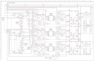
Power amplifier schematic