After correcting the original service
problem, perform the following safety check before releasing the set to the customer:
Check the antenna terminals, metal trim, “metallized” knobs, screws, and all
other exposed metal parts for AC leakage.
All of the units
included in the HT-ST9 (SAST9 - SA-WST9-Remote control) are required to
confirming operation of SA-ST9. Check in advance that you have all of the
units.
Be sure to keep your PC
used for service and checking of this unit always updated with the latest
version of your anti-virus software.
In case a virus affected unit was found during service, contact your Service
Headquarters
NETWORK INFORMATION WRITING AND CHECKING OF NETWORK-NFC OPERATION
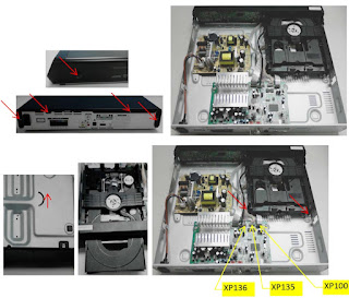
When
the complete MB1406 board or card WLAN-BT combo are replaced, execute the below
BD service mode. And check the operation of wireless or wired LAN and NFC.

Network information writing Procedure:
1.
Connect this unit with TV monitor.
2. Press the POWER button to turn the power on.
3. Press button in order of the STOP → [DISPLAY] → PAUSE → [UP] on the remote
commander.
(Make the interval when each button is pressed within one second)
4. Enter the BD service mode. The OSD menu on TV monitor can be operated by
remote commander.
5. Press the DOWN button on the remote commander to select “Diag”, and press
the [+] button on the remote commander.
6. Press the RIGHT button on the remote commander to select “Wireless LAN
Test”. (Screen 1)
7. Press the DOWN button on the remote commander to select “[5] Write P2P
address to Registry”.
8. Press the [+] button on the remote commander, wait until the display show
“Status: Write Successful!” (Screen 2).
9. Press the [BACK] button on the remote commander to return
to category select screen, and press the RIGHT button on the remote commander
to select “Bluetooth Device Test”. (Screen 3)
10. Press the [+] button on the remote commander to select “(1) Bluetooth
Enable”
11. Press the [+] button
on the remote commander, wait until the display show “Status: Bluetooth Enable
Successful!” (Screen 4).
12. Press the DOWN button on the remote commander to select “(3) Write
Bluetooth device address to Registry”.
13. Press the [+] button on the remote commander, wait until the display show
“Status: Write Successful!” (Screen 5).
14. Press the POWER button to turn the power off.

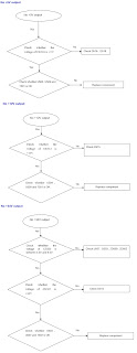
How to enter the BD
service mode
BD SERVICE MODE
Note: The operation in this mode must use a remote commander and TV monitor.
Setting method of the BD service mode:
1. Connect this unit with TV monitor.
2. Press the POWER button to turn the power on.
3. Press button in order of the STOP → [DISPLAY] → PAUSE → [UP] on the remote
commander.
(Make the interval when each button is pressed within one second)
4. Enter the BD service mode. The OSD menu on TV monitor can be operated by
remote commander.
WIRELESS SOUND COLD RESET
It
can initialize various backup information of Subwoofer (SAWST9).
Preparation:
Connect the Subwoofer (SA-WST9) and the Bar Speaker (SAST9) by wireless.
Procedure:
1. Press the POWER button to turn the power on.
2. Press the buttons on the remote commander in the order of STOP → [DISPLAY] →
[BACK] → [UP].
3. The on/standby indicator on the Subwoofer (SA-WST9) turns red and flashes,
then turns on orange.
4. Unplug the AC cord on
the Subwoofer (SA-WST9) from an outlet and insert the AC cord again.
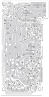
Power board schematic
and PWB


Amplifier board
schematic