Before Repair and Adjustment:
Disconnect
AC power, discharge Power Supply Capacitors C566~C569, C782 and C591 through a
10Ω, 5W resistor to ground.
DO NOT SHORT-CIRCUIT DIRECTLY (with a screwdriver blade, for instance), as this
may destroy solid state devices.
After repairs are completed, restore power gradually using a variac, to avoid over
current. Current consumption at AC 120V,
60 Hz in NO SIGNAL mode should be ~650mA.
Protection Circuitry
The
protection circuitry may have operated if either of the following conditions
are noticed:
• No sound is heard when the power is turned on.
• Sound stops during a performance.
The function of this circuitry is to prevent circuitry damage if, for example,
the positive and negative speaker connection wires are “shorted”, or if speaker
systems with an impedance less than the indicated rated impedance of the
amplifier are used.
If this occurs, follow the procedure outlines below:
1. Turn off the power.
2. Determine the cause of the problem and correct it.
3. Turn on the power once again after one minute.
Note : When the protection circuitry functions, the unit will not operate
unless the power is first turned OFF and then ON again.
Power supply: AC 120 V, 60Hz
Area: U.S.A - Canada, Signal system: NTSC

CD SECTION : RAE0152Z-3 TRAVERSE DECK SERIES
1.The traverse deck (optical
pickup) is an extremely high precision construction and should not be subjected to impact,
excessive vibration, or other types of rough handling.
2. In order to prevent static electricity damage to the laser diode, use a
short pin or similar tool to short the optical pickup’s flexible circuit boards
after they have been disconnected from the main circuit board.
3. Handle the flexible circuit boards with care; excessive force could cause
them to be broken.
4. Do not turn the pre-set variable resistor (for adjustment of the laser
power); it has been adjusted at the factory.
Beam
source: Semiconductor Laser
Total
stereo mode power: 65 W per channel (8 Ω)
Record
- playback head: Solid permalloy head
Erasure
head: Double gap ferrite head
Disc:
DVD-Video
Gear
for servicing (jig) information

Head
Azimuth adjustment
1. Connect the measuring
instrument.
2. Replace azimuth screws for both forward and reverse direction after removing
the screw-locking bond left on the head base.
3. Playback the azimuth adjustment portion (8kHz, -20dB) of test tape (QZZCFM).
Adjust the azimuth adjusting screw until the outputs of the L/Rch are
maximized.
Make sure that the difference in the peak level between the left and right
channels does not exceed 5dB.
4. Perform the same adjustment in reverse playback mode.
Check of the level difference forward and reverse directions
5.
Playback the playback gain adjustment portion (315Hz, 0dB) of test tape (QZZCFM).
Check if level difference between forward and reverse direction is within
1.5dB.
6. After the adjustment, apply screw lock to the azimuth adjusting screw.

Transistors and Diodes

Power Amp and Power schematic

Transformer circuit diagram

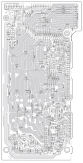
Printed circuit board – Power Amp
Repairing the mechanism is an expertise work. Please do not try to do it yourself at home.
No comments:
Post a Comment