Tuesday, April 30, 2013

SONY KLV-32BX500 - KLV-26NX400 - KLV-32NX400 - KLV-32NX500 - KLV-40NX500 - SERVICE ADJUSTMENTS - SERVICE MODE - LED BLINKING CODES


SERVICE ADJUSTMENTS
ACCESSING SELF DIAGNOSTIC MENU
  • While TV on standby mode, press the following sequence on the Remote commander.
[< Display> =>  <5> => <Vol Down> =>  <Power>]
  • To Reset Error Count & Error History, Press < 8 > à < 0 > key.
  • To Reset Panel Operation Time, Press < 7 > à < 0 > key
  • To exit, turn the power off using Remote.
ACCESSING SERVICE MODE
  • While TV on standby mode, press the following sequence on the Remote commander.

[< Display> => <5> => <Vol Up> => <Power>]
  • Use the ▲/▼ button to select the item you want to refer and press for details.
Example Status information.
GAISOU Adjustment (For Board Replacement)
  • When new board is replaced, please confirm the color ornamental of the TV set.
  • While TV on standby mode, press the following sequence on the Remote commander.
  • [<Display> <5> <Vol Up> <Power>]
  • Use the▲/▼ button to select the GAISOU item.
  • The color variation table of each TV set as below:
  • For example if color is Red than it should be, select 03 in the service mode of the TV set.
LED BLINKING
  • Standby LED Error Display and Board Replacement Order
  • Perform below countermeasures according to Standby LED blinking times.
  • When safety shutdown occurs, Standby LED display reports the cause by using the lightning patterns as indicated below.
  • The figure above shows LED display when Balancer Error causes SHUTDOWN. It repeats flashing for a specified number of times in 0.5sec/cycle and has a 3 seconds interval of lighting off.  Note that a 3 seconds interval of lighting off is fixed regardless of abnormal state types.
Click on images to Enlarge

H-BUSTER - HBTV 3204HD - LCD TV - POWER - SCHEMATIC [CIRCUIT DAGRAM]


 POWER-1
POWER - 2
POWER - INPUT
Click on images to Enlarge

Monday, April 29, 2013

ATLAS - PATIENT MONITOR - SERVICE MODE - SOFTWARE UPGRADE PROCEDURE [MEDICAL EQUIPMENT]


EXPLANATION OF AN ATLAS SERVICE SCREEN

Line A
Indicates that the Atlas is a model 220 and that the Atlas has a printer. If the Atlas did not have a printer then the text “with printer” would be absent. The date field following indicates the date the Atlas was last calibrated.
Line B
Starts with a numeric sequence. The first three digits are the model number of the Atlas. The next five numbers are the Atlas serial number. The next sequence,alphanumeric, indicates what software version is currently loaded into the Atlas. The third sequence, alphanumeric, indicates what version boot software is currently loaded into the Atlas.
Line C
Starts with the SpO2 OEM board used in the Atlas. There are two SpO2 OEM boards used in the Atlas. One is Nellcor and the other is Nonin. The next sequence indicates the model of the SpO2 board. The next sequence that starts with a letter “V” is the version software used with the current SpO2board. The date following the SpO2 software is the date  the OEM loaded the software into the SpO2board. SpO2 OEM software can not be upgraded. If the most current software is needed, you will need to replace the SpO2 board.
Line D
Is the CO2 information if your Atlas has CO2 installed. Only models 623 have CO2 installed. If your Atlas does not have CO2 installed then line Dwill be absent. If your Atlas has CO2 installed then line Dwill start with CO2 followed by a numeric number. That numeric value is the software loaded into the CO2 board. The next alphanumeric sequence, starting with a “V”, is the version of that software. The next numeric sequence starting with a “#” is the serial number of the CO2 board. The next sequence, a date, is the date the CO2 was last calibrated. The last sequence, a date, is the date the CO2was reset. CO2 OEM software can not be upgraded. If the current software is needed, you will have to replace the CO2 board.
SOFTWARE REVISION TABLE
SOFTWARE UPGRADE
NOTE:The following procedures are required to upgrade the software on a fully functioning Atlas or to reload software after replacing the CPU board. The download utility “atlas_dl.exe” loads the following files automatically.
  1. atlas.out.gz
  2. nvram_common.txt
  3. nvram_(model#).txt
  4. nvram_(language).txt
“Atlas_dl.exe” will also query the Atlas to determine what model number the Atlas is and what language to download.
Equipment or supplies required:
  • PC with Windows795 or higher
  • Atlas serial cable
  • File: atlas_dl.exe (Included in the Atlas Repair Software listed in Table)
NOTE: Make sure you have HyperTerminal turned off or the following utility download will not work.
Run the program atlas_dl.exe from the CD or copy the file toyour hard drive and run the program from there.
  • Connect the serial cable between the Atlas and the PC s’“COM1 port”.
  • Turn your computer on and locate the “atlas_dl.exe” file.
  • Double left click on the “atlas_dl.exe” file.
  • When the file starts to download, the CRT will go blank on the Atlas.
NOTE: Do not use the computer while the program is downloading.
  • After down loading is complete, check all alarm settings and all user advanced configuration settings since these are RESET by this utility software download procedure.
NOTE: Stop hereof you are just upgrading software on a fully functional Atlas monitor or if you have replaced the CPU board.
NOTE: If you have replaced the MAIN BOARD then you MUST continue with the next procedure (DOWNLOADING NVRAM FILES).
NOTE: Perform the following NVRAM downloading procedure if you have replaced the MAIN BOARD. The NVRAM resides on Main Board.
DOWNLOADING NVRAM FILES
Required Materials.
  1. Computer with Windows795 or higher.
  2. The latest Atlas repair software. Call your local Welch Allyn representative.
Once you have procured the latest Atlas Repair Software, you will be able  to run the programs straight from the CD or copy the files to your hard drive.
NOTE: Through Hyper Terminal you will need to load the following files:
  • nvram_cal_init.txt
  • nvram_common.txt
  • model# of Atlas
  • You will load “nvram200.txt” if your Atlas is a model 621xx.
  • You will load “nvram210.txt” if your Atlas is a model 622xx.
  • You will load “nvram220.txt” if your Atlas is a model 623xx.
“language.txt”Any combination ofor all of the following files
  1. “nvram_english.txt” for the English language
  2. “nvram_french.txt” for the French language
  3. “nvram_german.txt” for the German language
  4. “nvram_spanish.txt” for the Spanish language
  5. “nvram_potuguese.txt” for the Portuguese language
  6. “nvram_italian.txt” for the Italian language
  7. “nvram_chinese.txt” for the Chinese language
  8. “nvram_japanese.txt” for the Japanese language
  9. printer.txt (if fitted with a printer), or no_printer.txt. (if not fitted with a printer)
NOTE: After loading the preceding files you, must then type the following commands at the Pangea prompt.
  1. “nvram set serial xxxxx” where xxxxx is the serial number of the Atlas monitor.
  2. “nvram write” writes the information to memory.
  3. “hw reset” performs a hardware reset.
  • Connect the serial cable between the Atlas and the PC COM1 port.
  • Open HyperTerminal program on PC.
Hyper Terminal Settings are:
  • 9600 Baud, 8 bit word, 1 stop bit no parity, no flow control ANSI character set
  • Find HyperTerminal in Windows795 or higher
  • Start =>Pograms =>Accessories =>Communication =>HyperTerminal.
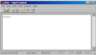
  • Turn Atlas on. You should see the Pangea prompt.
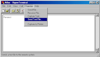
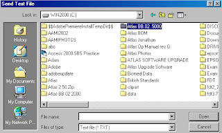
  • Scroll over to “Transfer” and then scroll down and choose “Send Text File”
  • Another window will then appear and prompt you for the location of the files. Double left click on that folder to open that directory. You can also run these programs from the CD.
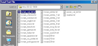
  • Once the folder is open, open the file “nvram_cal_init.txt”file by double left clicking on that file or by highlighting the file and then click on the Open button.
  • Remember that after you have download the files in this section and you must complete this entire “Downloading NVRAM files” section, that you must perform a complete calibration on the Atlas monitor.
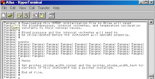
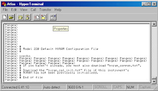
  • NOTE: After the nvram_cal_init.txthas executed you should see a Pangea screen similar to window as shown.
  • From your pangea window choose Transfer then choose Send Text File.
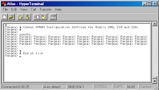
  • Open the directory where the file nvram_common.txtis located or open from the CD.
  • Double left click on nvram_comm.txtfile or highlight the file and then choose Open.
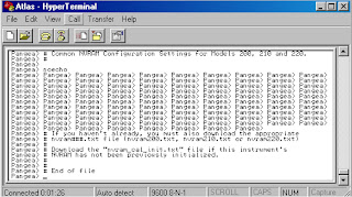
  • NOTE:After opening the nvram_common.txtfile you should see a screen similar to the window shown.
NOTE: Next you will download the model# of the Atlas by choosing only one of the three following files.
  1. If you have an Atlas model 621 then you will onlydownload the file nvram200.txt.
  2. If you have an Atlas model 622 then you will onlydownload the file nvram210.txt.
  3. If you have an Atlas model 623 then you will onlydownload the file nvram220.txt
  • Open the directory where the model number files are located or open from CD.
  • Open the file by double left clicking on the file that represents the model number of the Atlas you are working on or highlight that file then choosing Open.
  • NOTE:After opening the Atlas model# file you should see a Pangea screen similar to the window as shown.
NOTE: Next you will download the language(s) that you want the Atlas to store in its Advanced Configuration menu for languages. You can have one or all the languages loaded in the Atlas. Listed in Table are the language(s) choices and the files you will need to download to have the language(s)loaded in the Atlas. Each language you want loaded in the Atlas will require that the file associated with that language be loaded.
  • Open the directory where the language files are located or open from CD.
  • Double left click on language.txt file or highlight the file and then choose Open.
  • NOTE: After you download a language.txt file you should see a Pangea screen similar to Figure.
NOTE: Next you tell the Atlas if it does or does not have a printer.
  1. If the Atlas has a printer you will download the file nvram_printer.txt.
  2. If the Atlas does not have a printer then you will download the file nvram_no_printer.txt.
  • Open the directory where the printer.txt files are located or open from CD.
  • Double left click on the printer file or the no printer file or highlight the printer file or the no_printer fileand then choose Open.
  • NOTE: After you have downloaded the printer or no_printer file you should see a Pangea screen similar to the window as shown in Figure.
NOTE: The next three commands will require that you actually type the command at the Pangea prompt.
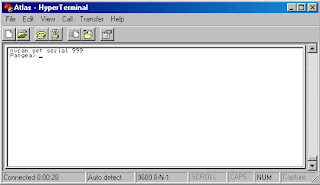
NOTE:XXXXX on line 17 is the Atlas 5 digit serial number. The serial number is located on the bottom of the Atlas. Make sure that you have a space between the command serial and the five numbers you are entering.
  • At the Pangea prompt type the following command “nvram set serial XXXXX”<ENTER>
NOTE: After you have typed the nvram set serial XXXXX command and hit ENTER you should see a Pangea screen similar to the example in Figure.
NOTE: To finish downloading the NVRAM files, type the next two commands at the Pangea prompt.
  • At the Pangea prompt type the command nvram write<ENTER>.
  • At the Pangea prompt type the command hw reset<ENTER>.

NOTE: The hw reset command will reboot the Atlas.
Remember that after you have download the files in this section and you must complete this entire “Downloading NVRAM files” section, that you must perform a complete calibration on the Atlas monitor.
NOTE:The firmware is not up grade able on the OEM boards (SpO2and CO2) boards. If higher version software is needed, then you will need to replace the OEM board.

ATLAS - PATIENT MONITOR - BP - CO2 & ET CO2 CALIBRATION PROCEDURE [MEDICAL EQUIPMENT]

CALIBRATION
Authorized Welch Allyn personnel or agents must service the Atlas Monitor at 6 month intervals. Maintenance requirements are specified for 6 month and 12 month service intervals. The monthly CO2.  Reset operation can be performed by the user.
  • Every 6 months: CO2Calibration.
  • Every 12 months: BP calibration, CO2 reset, battery voltage calibration, printer adjustment, and temperature calibration.  Complete functional test.
TOOLS REQUIRED FOR SERVICE Click on image to Enlarge
SETTING DATE & TIME
Check date and time before doing any calibration. Set date and time if incorrect. Set time and date as follows:
  • Turn Atlas on.
  • Press CLOCK button next to power on button to check date and time. Use the far right SELECT button to scroll. Highlight the date or time that needs changed.
  • Press the SET button to adjust date and time.
  • Press CLOCK button to exit.
Pangea Communication Protocol
The Pangea Communication Protocol allows interaction of the Atlas with the computer through the serial interface port. A prompt is emitted at the computer screen when the instrument powers up and is ready to accept commands. The prompt is Pangea>. A prompt is emitted after the completion of each pangea command. Pangea commands are case sensitive. They are in English only.
BP CALIBRATION
Required material.
  • 500cc vessel 4.
  • Squeeze bulb with one-way valve
  • PC with HyperTerminal
  • Calibrated digital manometer
  • Tubing and T fittings
  • Serial cable
  1. To start HyperTerminal you must have Windows7 95 or higher installed on your computer.
  2. From the Windows main screen follow the following sequence:  Start => Programs => Accessories => Communication => HyperTerminal.
  3. HyperTerminal setting are: 9600 baud rate, 8 bit word, 1 stop bit no parity, no flow control ANSI character set.
  • When you open HyperTerminal you will see a screen similar to the example in Figure. You will be prompted for a connection description. Choose any name. After you type in a name click OK.
  • The next window you will see will be the window as shown. Click on Connect using then click on COM1.
  • Set the port settings as shown in the example in Figure. Now click OK.
  • Connect the pressure meter, bulb, and 500cc vessel to BP port with “T” connectors as shown below..
  • Connect the Atlas to PC with serial cable.
  • Turn the Atlas on. Start Hyper Terminal on PC. Press the <Enter> key and you should see a Pangea>prompt.
NOTE: Take no more than 3 minutes for the 50mmHg calibration nor more than 3 minutes for the 250mmHg calibration as the Atlas will automatically, as a safety feature, open the blood pressure valve. If this happens you will have to turn the Atlas off then back on again and restart the calibration again.
50mmHg Calibration
  • Enter the following commands at the Pangea prompt.

Pangea> bp valve close<ENTER>
Pangea> bp safety off<ENTER>
Pangea> bp cal 5000 Do not press <ENTER> yet
  • Raise the pressure with bulb to as close to 50.00mmHg as possible.Now press <ENTER>.
  • Release the pressure.
250mmHg Calibration
  • Enter the following command Pangea> bp cal 25000 Do not press <ENTER> yet
  • Raise the pressure with bulb as close to 250.00 mmHgas possible. Now press < ENTER>
  • Enter the following command to save the calibration in the Atlas. Pangea> nvram write<ENTER>
  • Release the pressure.
CO2
Reset (623xx Models Only)
Required material.
  • Watertrap
  • Scrubber
NOTE: The Scrubber looks similar to a watertrap, but it is filled with white granules. The scrubber is a included withthe 623XX model only.
NOTE: Make sure date and time are correct before performing the CO2 reset.
  • Turn Atlas on. Make sure the watertrap and scrubber are Non attached to the Atlas.
  • Press the DATE/TIME button on the lower right of the monitor. The Set Date and Time and Other Options menu will be displayed.
  • Press the CO2 /RESP ALARMS Off button. The CO2.  Reset screen will appear.
  • You will see the following messages on the CRT.
“CO2
Reset”
“Install CO
2scrubber”
“Press Trend to abort”
  • Install the watertrap to the Atlas. Install the scrubber to the watertrap.
  • You will see the following instructions on the screen.
“Warming up” will be flashing on CRT.
“May take up to five minutes” on CRT.
“Press Trend to abort” on CRT.
  • After about 5 minutes you will see on the CRT.
“CO2
Reset”
“Reset complete”
“Remove CO2
scrubber”
“Press the trend button to exit”
  • Remove the CO2 watertrap and scrubber.
  • Press TREND button to return to idle screen.
Replace watertrap after every six hours of use. Treat watertrap and used CO2 sample lines as bio hazard material.
ET CO2 Calibration
Required material:
  • Tank of approximately 10% CO2, balance N2 (certified) Blood Gas Mixture.
  • Tubing and T connectors.
  • Watertrap and scrubber.
  1. Make sure the watertrap and scrubber is not attached to the Atlas. Turn the Atlas on.
  2. Place the instrument into the Service Mode by pressing the DATE/TIME button. Make sure date and time are correct. Press the LEAD SELECT button.
  3. Press SELECT button and scroll down to Calibrate CO2.
  4. The message “Install CO2Scrubber” will appear on the right side of screen.
  5. Attach the scrubber to the water trap.
  6. Insert the scrubber/water trap assembly into water trap socket. The message.  “Enter span gas value using Set button 10%” will appear.
  7. Press the SET button to change the value of span gas being used. The factory default value is 10%. Calibrate with a 8% to 12% certified CO2 concentration known to be ±0.01%).
  8. The message press “BP Start/Cancel” will appear at the bottom right of CRT. Press the BP/Start/Cancel button.
  9. If you receive a “Calibration Failed” message at this point, check the date. If date is 2022 or above it will fail CO2 calibration.
  10. Next you will see a message “Warming up”. After the Atlas warms up you will see a message “Attach CO2 gas”. Remove the scrubber from the CO2 water trap. Do not remove water trap.
  11. Attach the certified source of CO2gas to the CO2 side-stream sampling tube as per Figure below.
  • Adjust the CO2 regulator just enough to allow a small amount of gas to flow out of the vent (approximately 2 psi).
  • Press the BP START/CANCEL button. The message: “Sampling” will appear on CRT. “CO2 calibration successful” or “CO2calibration failed” will appear on the CRT display.
  • Press the TREND button to exit.
CAUTION: IMPROPER USE, STORAGE OR HANDLING OF COMPRESSED GAS VESSELS CAN CAUSE DEATH ORINJURY. FOLLOW GAS MANUFACTURES SAFETY PROCEDURES.

PANASONIC PLASMA TH-42PY8P - TH-42PZ8P - TH-42PZ8E - POWER LED BLINKING CODES - TROUBLESHOOTING CHART


LED BLINKING CODES
When an abnormality has occurred the unit, the protection circuit operates and reset to the stand by mode. At this time, the defective block can be identified by the number of blinks of the Power LED on the front panel of the unit.     {Click on image to Enlarge}
NO POWER
First check point
There are following 2 states of No Power indication by power LED.
  • No lit
  • Red is lit then turns red blinking a few seconds later.
NO PICTURE
LOCAL SCREEN FAILURE
Plasma display may have local area failure on the screen. The possible defect P.C.B. for each local area.

PANASONIC PLASMA TH-42PY8P - TH-42PZ8P - TH-42PZ8E - SERVICE MODE - SERVICE TOOL MODE - MEASUREMENTS & ADJUSTMENTS - TROUBLESHOOTING


TO ENTER SERVICE MODE
While pressing [VOLUME ( - )] button of the main unit, press [0] button of the remote control three times within 2 seconds.
SERVICE MODE DISPLAY
KEY COMMAND
[1] button...Main items Selection in forward direction
[2] button...Main items Selection in reverse direction
[3] button...Sub items Selection in forward direction
[4] button...Sub items Selection in reverse direction
[RED] button...All Sub items Selection in forward direction
[GREEN] button...All Sub items Selection in reverse direction
[VOL] button...Value of sub items change in forward direction ( + ), in reverse direction ( - ).

Contents of adjustment mode
  • Value is shown as a hexadecimal number.
  • Preset value differs depending on models.
  • After entering the adjustment mode, take note of the value in each item before starting adjustment.
TO EXIT SERVICE MODE
  • Switch off the power with the [POWER] button on the main unit or the [POWER] button on the remote control.
SERVICE TOOL MODE
  • Select [SRV-TOOL] in Service Mode.
  • Press [OK] button on the remote control.
Display of SOS History
  • SOS History (Number of LED blinking) indication.
  • From left side; Last SOS, before Last, three occurrence before, 2nd occurrence after shipment, 1st occurrence after shipment.
  • This indication except 2nd and 1st occurrence after shipment will be cleared by [Self-check indication and forced to factory shipment setting].
POWER ON TIME/COUNT
  • To display TIME/COUNT menu, highlight position, then press MUTE for 3sec.
  • Time: Cumulative power on time, indicated hour : minute by decimal
  • Count: Number of ON times by decimal
  • Note: This indication will not be cleared by either of the self-check or any command.
TO EXIT
  • Disconnect the AC cord from wall outlet or switch off the power with the [POWER] button on the main unit.
HOTEL MODE
  • Access command to the Hotel mode setup menu In order to display the Hotel mode setup menu, enter the following command (within 2 second).
  • [TV] : Vol. [Down] + [REMOTE] : AV (3 times)
  • Then, the Hotel mode setup menu is displayed.
To exit the Hotel mode setup menu
  • Disconnect AC power cord from wall outlet or switch off the power with the [POWER] button on the main unit.
Explain the Hotel mode setup menu
MEASUREMENTS & ADJUSTMENTS
Item / Preparation
  • Input a white signal to plasma video input.
  • Set the picture controls as follows.
  • Picture menu:
Dynamic
PNR: OFF
Aspect: 16:9
Caution
  • First perform Vsus adjustment.
  • Confirmation of Vscn voltage should be performed after confirmation of Vad adjustment. When Vad= -140V, Voltage of Vscn is 8V ±1V.
See the Panel label.
Adjustments
  • Adjust driver section voltages referring the panel data on the panel data label.
  • Check or adjust the following voltages with the multimeter.
INITIALIZATION PULSE ADJUST
  • Input the White signal to plasma video input.
  • Set the picture controls as follows.
Picture menu : Dynamic
PNR: OFF
Aspect : 16:9
  • Connect Oscilloscope to TPSC1 (SC).  Check the voltage (T2) at 100 us period on the down slop.
Quick adjustment after P.C.B. exchange.
  • Adjust the following voltages with the multimeter
{Click on images to Enlarge}
See the Panel label.
Caution:
Absolutely do not reduce Vsus below +Ve not to damage the P.C.B.
ADJUSTMENT VOLUME LOCATION
TEST POINT LOCATION
BOARD NAME AND LOCATION

Applicable signals
Troubleshooting.
Use the self-check function to test the unit.
  • Checking the IIC bus lines
  • Power LED Blinking timing
Check of the IIC bus lines.   How to access
Self-check indication only:
  • Produce TV reception screen, and while pressing [VOLUME ( - )] button on the main unit, press [OK] button on the remote control for more than 3 seconds.
Self-check indication and forced to factory shipment setting:
  • Produce TV reception screen, and while pressing [VOLUME ( - )] button on the main unit, press [MENU] button on the remote control for more than 3 seconds.

SCREEN DISPLAY


Check Point
Confirm the following parts if NG was displayed.
To Exit
Disconnect the AC cord from wall outlet or switch off the power with the [POWER] button on the main unit