
MPU controls the functions switching for each IICs through IIC bus in this chassis.
The following setting and adjustment can be adjusted by
remote control in Service Mode.
SERVICE MODE-1
- In sound menu, set BASS to MAXIMUM, and set TREBLE to MINIMUM.
- Set the Volume to minimum, and set the off timer.
- Simultaneously press Recall button on remote control and DOWN button on the TV set.
SERVICE MODE-2
- Set the channel to CH99.
- Select the EQ 12kHz.
- Press Mute button on remote control and DOWN button on the TV set.
- To exit to Service mode, press EXIT or Power button on remote control.


OPTION DESCRIPTION


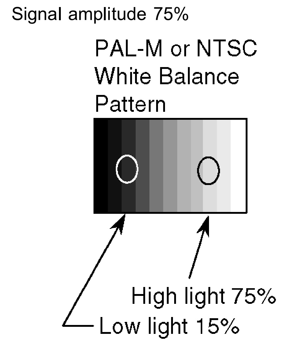
PAL-WHITE BALANCE ADJUSTMENT
- Display the white balance pattern.
- Check that the color balance is “cool”.
- Enter the <Service1> mode.
- Select “G-CUTOFF” item, using the color-key “Red” or “Green”, and set to “128”, using the color-key “Yellow” or “Blue”. Also, “B-CUTOFF” and “R-CUTOFF” set to “128”.
- Set “G-DRIVE” at “224”.
- Touch the signal receiver of color analyzer to the highlight window’s center, and adjust B drive and R drive so x, y become the “Color balance Cool”.
- Set “ALL-DRIVE” to “252”.
- Set color balance to “Normal”.
- Fix G cutoff , B cutoff and R cutoff at “128”.
- Fix G drive at “224”.
- Adjust B drive and R drive so the highlight window’s x, y become the “Color balance “Normal”.
- Set “ALL-DRIVE” to “252”.
- Set color balance to “Warm”.
- Set G cutoff, B cutoff and R cutoff to “128”.
- Set G drive to “224”.
- Adjust B drive and R drive so the highlight window’s x, y become the “Color balance Warm”.
- Set “ALL-DRIVE” to “252”.

HD-WHITE BALANCE ADJUSTMENT
- Display the white balance pattern.
- Check that the color balance is “cool”.
- Enter the <Service1> mode.
- Select “G-CUTOFF” item, using the color-key “Red” or “Green”, and set to “128”, using the color-key “Yellow” or “Blue”. Also, “B-CUTOFF” and “R-CUTOFF” set to “128”.
- Set “G-DRIVE” at “224”.
- Touch the signal receiver of color analyzer to the highlight window’s center, and adjust B drive and R drive so x, y become the “Color balance Cool” in the below table.
- Set “ALL-DRIVE” to “252”.
- Set color balance to “Normal”.
- Fix G cutoff, B cutoff and R cutoff at “128”.
- Fix G drive at “224”.
- Adjust B drive and R drive so the highlight window’s x, y become the “Color balance “Normal” in the below table.
- Set “ALL-DRIVE” to “252”.
- Set color balance to “Warm”.
- Set G cutoff, B cutoff and R cutoff to “128”.
- Set G drive to “224”.
- Adjust B drive and R drive so the highlight window’s x, y become the “Color balance Warm” shown in the below table.
- Set “ALL-DRIVE” to “252”.


SUB-BRIGHT ADJUSTMENT
- Display the 10 step gray-scale pattern for adjusting sub-bright from video input.
- Use "Sub-Bright" in the <Sevice1> mode to adjust so the 6th section shows up and the 7th fades away.
Sub-Bright (upper) A0-0116
Sub-Bright (lower) A0-0117

ABL ADJUSTMENT
- Connect the set’s AC power to the wattmeter.
- Input the signal (top half: color bar, Bottom half :Horizontal 10steps bar).
- Select the “PWRCTL” item in the <Service1> mode.
- Adjust PWRCTL so the set’s power consumption is 289 (+5/-10)W
- The initial data are
Data address : A0-0102
Default data : 0×00
The power and data are in reverse relationship. Data is
displayed by 2’C. (Lower the data to raise the power.)
Raising direction (▲): 0 à255, 254, 253.....
Lowering direction (▼):0 à1, 2, 3.....
There is a possibility that the adjustment value can do two
places, adjust it in that case, that the value of PWRCTL is large.

SUB-CONTRAST ADJUSTMENT
Adjustment AV system
- Receive AV1 (PAL-M or NTSC 100% Full White or Split Color bar shown as below).
- Go into service mode, choose Sub-Contrast, and it checks that data value is 512. (It checks that an initial value is a default)
- The color key yellow button of remote control is pushed
- The OSD character of sub-contrast becomes red. (Inside under automatic adjustment)
- The OSD character of sub-contrast returns to white.
- End.
- Receive a RF. (PAL-M or NTSC 100% Full White or Split Colour bar shown as below).
- Go into service mode, choose Sub-Contrast, and it checks that data value is 512. (It checks that an initial value is a default)
- The color key yellow button of remote control is pushed.
- The OSD character of sub-contrast becomes red. (Inside under automatic adjustment)
- The OSD character of sub-contrast returns to white.
- End.

Adjustment HD system
- Receive Component: (1080i/ 60Hz or 1080i/ 50Hz, 100% Full White or Split color bar as shown below).
- Go into service mode, choose Sub-Contrast, and it checks that data value is 384. (It checks that an initial value is a default)
- The color key yellow button of remote control is pushed.
- The OSD character of sub-contrast becomes red. (Inside under automatic adjustment)
- The OSD character of sub-contrast returns to white.
- End.
