Saturday, May 29, 2021

Panasonic 50 inch Class 1080p Plasma HDTV TC-50PS14-GPF12DU Chassis – Service mode, Adjustments, LED blinking codes, SMPS circuit diagram [Schematic], Troubleshooting

 Power source - AC 120 V, 60 Hz

How to enter into Service Mode

While pressing [VOLUME ( - )] button of the main unit, press [INFO] button of the remote control three times within 2 seconds.

Service mode screen

Contents of adjustment mode
• Value is shown as a hexadecimal number.
• Preset value differs depending on models.
• After entering the adjustment mode, take note of the value in each item before starting adjustment.

How to exit
Switch off the power with the [POWER] button on the main unit or the [POWER] button on the remote control.

Service tool mode:  How to access
1. Select [SRV-TOOL] in Service Mode.
2. Press [OK] button on the remote control.

Display of SOS History
SOS History (Number of LED blinking) indication.
From left side; Last SOS, before Last, three occurrence before, 2nd occurrence after shipment, 1st occurrence after shipment.
This indication except 2nd and 1st occurrence after shipment will be cleared by [Self-check indication and forced to factory shipment setting].
POWER ON TIME/COUNT
Note : To display TIME/COUNT menu, highlight position, then press MUTE for (3sec).
Time : Cumulative power on time, indicated hour : minute by decimal
Count : Number of ON times by decimal
Note : This indication will not be cleared by either of the self-checks or any other command.
Exit
1. Disconnect the AC cord from wall outlet.

Hotel mode
Check of the IIC bus lines:  How to access
Self-check indication only:
Produce TV reception screen, and while pressing [
VOLUME ( - )] button on the main unit, press [OK] button on the remote control for more than 3 seconds.
Self-check indication and forced to factory shipment setting:
Produce TV reception screen, and while pressing [
VOLUME ( - )] button on the main unit, press [MENU] button on the remote control for more than 3 seconds.
Exit
Disconnect the AC cord from wall outlet.

Restrict a function for hotels.
2. Access command to the Hotel mode setup menu
In order to display the Hotel mode setup menu, please
enter the following command (within 2 second).
[TV] : Vol. [Down] + [REMOTE] : INPUT (3 times)
Then, the Hotel mode setup menu is displayed.

3. To exit the Hotel mode setup menu
Disconnect AC power cord from wall outlet.
4. Explain the Hotel mode setup menu.

Troubleshooting
Use the self-check function to test the unit.
1. Checking the IIC bus lines
2. Power LED Blinking timing.

Power LED Blinking timing chart
1. Subject
Information of LED Flashing timing chart.
2. Contents
When an abnormality has occurred the unit, the protection circuit operates and reset to the stand by mode. At this time, the
defective block can be identified by the number of blinks of the Power LED on the front panel of the unit.

No Power
First check point
There are following 2 states of No Power indication by power LED.
1. No lit
2. Red is lit then turns red blinking a few seconds later


Local screen failure

Adjustment Procedure

1. Input a white signal to plasma video input.
2. Set the picture controls as follows.
Picture menu: Vivid
Normal: Set
Aspect: Full
Caution
1. First perform Vsus adjustment.
2. The Vscn voltages are measured from the Vad (Vad_base), but may be measured from the GND (GND_base) in an unavoidable case,

Adjustments
Adjust driver section voltages referring the panel data on the panel data label.
Check or adjust the following voltages with the multimeter.

Initialization Pulse Adjust
1. Input the White signal to plasma video input.
2. Set the picture controls as follows.
Picture menu : Vivid
Normal : Set
Aspect : Full
3. Connect Oscilloscope to TPSC1 (SC).
Check the voltage (T2) at 100μs period on the down slop.

P.C.B. (Printed Circuit Board) exchange

Caution
1. To remove P.C.B., wait 1 minute after power was off for discharge from electrolysis capacitors.
Quick adjustment after P.C.B. exchange
Adjust the following voltages with the multimeter.

White balance adjustment

POWER BOARD - ETX2MM747AFK: schematic


Tuesday, May 18, 2021

Sharp LC48CFG4042E, Sharp LC49CFE4041E – How to enter the service mode, Software update, Service mode adjustments


LC-48CFG4042E, LC-49CFG4041E, LC-49CFE4042E – Sharp LCD TV-service mode, service mode adjustments, software update, Panel and EMC setting and more

MSD3463 Factory Menu Specification

How to Enter Factory Menu
Press the RC buttons in this sequence: “Menu 1 1 4 7” to enter the factory menu.

INTRODUCTION
SHIPPING INIT:
TV Initialization to set default TV parameters. Designed for Shipment.
AGING MODE: TV aging mode switch.
ADC ADJUST: Change ADC parameters
PICTURE SETTING: Change Picture Setting
SOUND SETTING: Change Sound Setting
GENERAL SETTING: Some other settings usually used, and also for Debug.
PANNEL SETTING: Change panel parameters like BitMap, ODD.EVEN and Etc.
EMC SETTING: Some settings may affect EMC.
SYSTEM INFO: Display system information.
BOARD INIT: Factory reset.
SW UPGRADE: Software update item.

ADC ADJUST & WHITE BALANCE AUTO ADJUST
It’s for adjusting the YPBPR and PC color. Press key “right” or “ok” to enter the subpage.
Auto Adjust: Start to auto color to get ADC value.
Source: Set source for adjusting
R-Gain: Display current ADC R value.
G-Gain: Display current ADC G value.
B-Gain: Display current ADC B value.
R-Offset: Display current ADC R offset value.
G-Offset: Display current ADC G offset value.
B-Offset: Display current ADC B offset value
Reset: Reset to default values.

PICTURE
Source:
Choose source
Picture Mode: Change picture mode parameters
Picture Curve: Picture mode parameter curve.
WB Adjust: White Balance parameter setting
Over scan: Over scan setting
PQ Advanced: For PQ Adjustment.
Gamma: Preset several Gamma Curves, for PQ debug.
DLC: Preset several Curves, for PQ debug.
HDMI RGB Range: Change Limit range or Full Range.

PICTURE MODE
Source:
Choose sources
Picture Mode: Select picture mode which is same with main menu.
Contrast: Adjust contrast which is same with main menu.
Brightness: Adjust brightness which is same with main menu.
Color: Adjust Color which is same with main menu.
Sharpness: Adjust Sharpness which is same with main menu.
Tint: Adjust tint which is same with main menu.

PICTURE CURVE
Adjust the real value of main menu from 0 to 100
Source: Choose source
Contrast: Adjust the real contrast for main menu from OSD 0 to OSD 100.
Brightness: Adjust the real brightness for main menu from OSD 0 to OSD 100.
Color: Adjust the real color for main menu from OSD 0 to OSD 100.
Sharpness: Adjust the real sharpness for main menu from OSD 0 to OSD 100.
Tint: Adjust the real tint for main menu from OSD 0 to OSD 100.

CONTRAST
Contrast-0:
The real value of main menu contrast OSD 0
Contrast-25: The real value of main menu contrast OSD 25
Contrast-50: The real value of main menu contrast OSD 50
Contrast-75: The real value of main menu contrast OSD 75
Contrast-100: The real value of main menu contrast OSD 100
The Brightness, Color, Sharpness, Tint are same with the contrast.

WB [White Balance] ADJUST
White-Balance Adjustment
This page only for current source White Balance Adjustment.  Different source may have different values. There are Warm, Cool, Normal modes and save every separate source. We can change the R-GAIN, G-GAIN, B-GAIN, R-OFFSET, G-OFFSET, B-OFFSET.
SYNC ALL: SYNC the white balance of the current source to all other sources.

White Balance
 Load 80% White pattern from signal generator
 Enter Factory Menu by pressing MENU + 1147
 Choose 3 PICTURE SETTING
 Choose 3 WB ADJUST
 Change 0 SOURCE to HDMI
 In 1 COLOUR TEMP choose Warm/Normal/Cold
 Change R-GAIN/G-GAIN/B-GAIN to meet specification

OVERSCAN
This page can adjust over scan.
Note: Over scan should check with every timing.

PQ ADVANCED
PQ Adjustment Page
Adjust luminance, Colors, peaking, NR and etc.

SOUND
Source:
Choose source
Sound Mode: BASS, TREBLE, EQ-Settings.
Volume Curve: Adjust volume curve.
Audio Pre-scale: Adjust the power of current source.
Audio AVC: For Software Designer Only
PEQ: For Software Designer Only
Audio DRC: For Software Designer Only
Treble/Bass Range: Adjust the Treble/Bass range
SPDIF Audio Delay: Adjust the SPDIF Audio delay.

VOLUME CURVE
Volume Offset:
User overall volume control, every source has a unique value.
VOL1–VOL100: All sources share a same value, make sure the next value bigger than the before.

GENERAL SETTING
Power Mode:
On/Standby/Last boot status.
LOGO: Set boot logo on or off.
Test Pattern: Test pictures from IC which can help to judge panel issue or not.
Channel Export: Export channel table.
Channel Import: Import channels table to TV.
Watch Dog: watch dog switch.

DEBUG
UART Debug:
For Software Designer only
QMAP: Map adjustment
Timer Test: Speed up timer

PANEL and EMC SETTING

SYSTEM INFORMATION

SW UPGRADE
Upgrade TV: update item
Bin Name: Software bin name.

Upgrading the software
MSD3463 has two kinds of chips: MSD3463GSA and MSD3463GU. Please make sure that you get
the correct upgrading file for a certain chipset (refer to the chart below).   Introducing 4 upgrading methods one by one: User menu Upgrading, Power on Upgrading, Factory Setting Upgrading, ISP Upgrading. The former three are most commonly-used.

Preparation
This step only applies to power integrated board.
Prepare mini power board(CN.UPGRADE01) for upgrading.

Connect the mini board with main board as below:

Make sure connect the 12V to 12V and GND to GND, or it will cause hardware damage.
 The main board should be connected to mains to work if we do not use the CN.UPGRADE01 board. The power module of main board have more than thousands of volts at working. It is easily leads personal injury or damage to equipment if  mistakenly touch the main board or some objects fallen into the main board during the upgrading procedure. So  use the CN.UPGRADE01 board to reduce the risk of upgrading.

Please keep the electricity ON in the upgrade process.
Operation Procedure
Copy the Upgrading File (SW) to a USB disk and then insert it to the USB port. Search for the SETUP and select Software Update by Left or Right  remote control key on User OSD Menu. The pictures below are the upgrading procedure for your reference:

Upgrade Prompt
When upgrading, the TV set will light panel according to the panel parameter, and display the progress bar. If the panel parameter of board matches the panel, you will see the following image:

100% indicates the upgrade finished, and TV will auto reboot after user menu upgrading finished.
 Upgrade Flashing Status
You can judge the upgrade progress by flashing of the remote control LED light:
Upgrading:
Red 1000ms Green 1000ms alternates, the TV set will turn to Upgrade succeed or Upgrade Failed status after the upgrading process.
Main program upgrade succeed:
Red 250ms Green 250ms alternates, flashing before power off.
Main program upgrade Failed:
Red 1750ms Green 250ms alternates, flashing before power off.
Notes: In the upgrade process, as timer software is used to control flashing, situations such as LED light stuck when creating partition of flash, is normal phenomenon.
Power On Upgrading
Copy the SW to a USB disk, link it to the USB port, Re-power on, if the LED blinks continually, it means the upgrading is on process, while the LED light off means the upgrading has been completed.

Factory Setting Upgrading
Press <MENU>+1147 to enter the factory setting, search for the “Upgrade” item by the remote control, just like the picture below, then you can follow the steps in the screen.


Install USB driver. Make sure the USB ISP tool is connected to PC before setup


HOTEL MODE
To enter Hotel mode you need press buttons on RC in following sequence: MENU 7 9 0 6.
Structure of Hotel menu:
1. Hotel Mode – on/off hotel mode
2. Source Lock – you can lock any source
3. Default Source – source which appears after turn on TV
4. Default Prog – channel which appears after turn on TV
5. DTV channel type – type of channel which appears after turn on TV
6. Default volume – volume which will be set itself after turn on TV
7. Max volume – maximum volume which can be set
8. Import Database – import all channels and settings from USB
9. Export Database – export all channels and setting to USB
10. Clear Lock – reset all hotel mode settings.


Friday, May 07, 2021

Philips 40PFT6709- Service mode, Option settings, Alignments, Error codes, LED blinking codes and more - TPM14.2A Chassis


Always respect voltages. While some may not be dangerous in themselves, they can cause unexpected reactions that are best avoided. Before reaching into a powered TV set, it is best to test the high voltage insulation.
It is easy to do, and is a good service precaution.

The TPM14.2A LA is a new chassis launched in Asia in 2014.
The whole range is covered by SCALER MT5591.
The major deltas versus its predecessor DVB-TC; DVB-TC/T2, with also multi-media, 3D, Ambilight, WIFI, Smart TV, Light Sensor functionality.
The TPM14.2A LA chassis comes with the following styling:
• series xxPFT6700
• series xxPFT6900
• series xxPUT8500
• series xxPUT8600

Key components of this chassis are:
• SCALER MT5591IVDJ HSBGA-758 TV Processor
• TUNER EUROPE - SUT-RE231ZN (DVB-T/C, T2 analogue)
• DEMODULATOR CXD2837ER-T4 VQFN-48
• STA381BWTR 20W VQFN-48 for AUDIO Amplifier
• THGBM5G5A1JBAIR 4GB P-VFBGA153 for EMMC IC


It should be noted that on the European Service website, “Alternative BOM” is referred to as “Design variant”.
The third digit in the serial number (example: AG2B0335000001) indicates the number of the alternative B.O.M. (Bill Of Materials) that has been used for producing the specific TV set. In general, it is possible that the same TV model on the market is produced with e.g. two different types of displays, coming from two different suppliers. This will then result in sets which have the same CTN (Commercial Type Number; e.g. 28PW9515/12) but which have a different B.O.M. number.
By looking at the third digit of the serial number, one can identify which B.O.M. is used for the TV set he is working with.
If the third digit of the serial number contains the number “1” (example: AG1B033500001), then the TV set has been manufactured according to B.O.M. number 1. If the third digit is a “2” (example: AG2B0335000001), then the set has been produced according to B.O.M. no. 2. This is important for ordering the correct spare parts.
For the third digit, the numbers 1...9 and the characters A...Z can be used, so in total: 9 plus 26= 35 different B.O.M.s can be indicated by the third digit of the serial number.
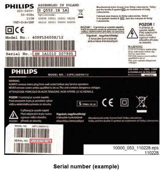
Identification

The bottom line of a type plate gives a 14-digit serial number. Digits 1 and 2 refer to the production centre (e.g. SN is Lysomice, RJ is Kobierzyce), digit 3 refers to the B.O.M. code, digit 4 refers to the Service version change code, digits 5 and 6 refer to the production year, and digits 7 and 8 refer to production week (in example below it is 2010 week 10 / 2010 week 17). The 6 last digits contain the serial number. 

Board Level Repair (BLR) or Component Level Repair (CLR)
If a board is defective, consult your repair personal to decide if the board has to be exchanged or if it should be repaired on component level.
If your repair personal says the board should be exchanged completely, do not solder on the defective board. Otherwise, it cannot be returned to the O.E.M. supplier for back charging.


Service Mode.  Service Alignment Mode (SAM)

How to Activate SAM
To activate SAM, use one of the following methods:
• Press the following key sequence on the remote control transmitter: “062596”, directly followed by the “INFO/OK” button. Do not allow the display to time out between entries while keying the sequence.
• Or via ComPair.
After entering SAM, the following items are displayed, with “SAM” in the upper right corner of the screen to indicate that the television is in Service Alignment Mode.

Software Identification, Version, and Cluster
The software ID, version, and cluster will be shown in the main menu display of SAM and CSM.
The screen will show: “AAAAB-X.YYY”, where:
• AAAA is the chassis name: QN142A x.yy.
• B is the region indication: E = Europe, A = AP/China, U = NAFTA, L = LATAM.
• X is the main version number: this is updated with a major change of specification (incompatible with the previous software version). Numbering will go from 1 - 99 and AA - ZZ.
- If the main version number changes, the new version number is written in the NVM.
- If the main version number changes, the default settings are loaded.
• YYY is the sub version number: this is updated with a minor change (backwards compatible with the previous versions). Numbering will go from 000 - 999.
- If the sub version number changes, the new version number is written in the NVM.
- If the NVM is refreshed, the software identification, version, and cluster will also be written to NVM.

Display Option Code Selection
When after an SSB or display exchange, the display option code is not set properly, it will result in a TV with “no display”.
Therefore, it is required to set this display option code after such a repair.
To do so, press the following key sequence on a standard RC transmitter: “
062598” directly followed by MENU and “xxx”, where “xxx” is a 3 digit decimal value of the panel type.  

When the value is accepted and stored in NVM, the set will switch to Stand-by,
to indicate that the process has been completed.
During this algorithm, the NVM-content must be filtered, because several items in the NVM are TV-related and not SSB related (e.g. Model and Prod. S/N). Therefore, “Model” and “Prod. S/N” data is changed into “See Type Plate”. In case a call centre or consumer reads in CSM mode.

How to Navigate
• In the SAM menu, select menu items with the UP/DOWN keys on the remote control transmitter. 

The selected item will be indicated. When not all menu items fit on the screen, use the UP/DOWN keys to display the next/previous menu items.
• With the “LEFT/RIGHT” keys, it is possible to:
– (De) activate the selected menu item.
– (De) activate the selected sub menu.
– Change the value of the selected menu item.
• When you press the MENU button once while in top level SAM, the set will switch to the normal user menu (with the SAM mode still active in the background).
• Press the following key sequence on the remote control transmitter: “
062596” directly followed by the “Home/Menu” button to switch to SDM (do not allow the display to time out between entries while keying the sequence).
How to Store SAM Settings
To store the settings changed in SAM mode (except the RGB Align settings), leave the top level SAM menu by using the POWER button on the remote control transmitter or the television set. The mentioned exceptions must be stored separately via the STORE button.
How to Exit SAM
Use one of the following methods:
• Switch the set to STANDBY by pressing the mains button on the remote control transmitter or the television set.
• Via a standard RC-transmitter, key in “00” sequence.
Note: When the TV is switched “off” by a power interrupt while in SAM, the TV will show up in “normal operation mode” as soon as the power is supplied again. The error buffer will not be cleared.

How to Activate the Factory mode
To activate the Factory mode, use the following method:
• Press the following key sequence on the remote control transmitter: from the “
menu/home” press “1999”, directly followed by the “Back/Return” button. Do not allow the display to time out between entries while keying the sequence.
After entering the Factory mode, the following items are displayed,

How to Exit the Factory mode
Use one of the following methods:
• Select
EXIT-FACTORY from the menu and press the “OK” button.
Note: When the TV is switched “off” by a power interrupt, or normal switch to “stand-by” while in the factory mode, the TV will show up in “normal operation mode” as soon as the power is supplied again. The error buffer will not be cleared.

SAM mode and Factory mode overview.


How to Copy NVM Data to/from USB.

When copying data to and from a USB memory stick, the folder “repair” is used. When inserting an empty USB memory stick, and downloading data to the stick, the TV will create this folder.
When sending data from a USB memory stick to a TV, the intended data must be available in the “repair” folder.
Note that when copying EDID data to the TV, all necessary EDID files must be in this folder.
Service mode overview for your reference.

Error Codes
Error codes are required to indicate failures in the TV set. In principle a unique error code is available for every:
• Activated (SW) protection.
• Failing I2C device.
• General I2C error.
The last five errors, stored in the NVM, are shown in the Service menu’s. This is called the error buffer.  The error code buffer contains all errors detected since the last  time the buffer was erased. The buffer is written from left to  right. When an error occurs that is not yet in the error code buffer, it is displayed at the left side and all other errors shift one position to the right.
An error will be added to the buffer if this error differs from any error in the buffer. The last found error is displayed on the left.
An error with a designated error code never leads to a deadlock situation. It must always be diagnosable (e.g. error buffer via OSD or blinking LED or via ComPair).
In case a failure identified by an error code automatically results in other error codes (cause and effect), only the error code of the MAIN failure is displayed.

How to Read the Error Buffer.
You can read the error buffer in three ways:
• On screen via the SAM/CSM (if you have a picture).
Example:
ERROR: 000 000 000 000 000: No errors detected
ERROR: 013 000 000 000 000: Error code 13 is the last and only detected error
ERROR: 034 013 000 000 000: Error code 13 was detected first and error code 34 is the last detected (newest) error

• Via the blinking LED procedure (when you have no picture).

Error codes.
In this chassis only “layer 2” error codes are available and point to problems on the SSB. They are triggered by LED blinking when CSM is activated. Only the following layer 2 errors are defined:

How to Clear the Error Buffer.
The error code buffer is cleared in the following cases:
• By using the CLEAR command in the SAM menu
• By using the CLEAR command in the Factory mode:
• By using the following key sequence on the remote control transmitter: “
062599” directly followed by the OK button.
• If the contents of the error buffer have not changed for 50 hours, the error buffer resets automatically.
Note: If you exit SAM by disconnecting the mains from the television set, the error buffer is not reset.

The Blinking LED Procedure.
The software is capable of identifying different kinds of errors.
Because it is possible that more than one error can occur over time, an error buffer is available, which is capable of storing the last five errors that occurred. This is useful if the OSD is not working properly.
Errors can also be displayed by the blinking LED procedure.
The method is to repeatedly let the front LED pulse with as many pulses as the error code number, followed by a period of 1.5 seconds in which the LED is “off”. Then this sequence is repeated.
Example 
(1): error code 4 will result in four times the sequence LED “on” for 0.25 seconds / LED “off” for 0.25 seconds. After this sequence, the LED will be “off” for 1.5 seconds. Any RC command terminates the sequence. Error code LED blinking is in red color.

Example (2): the content of the error buffer is “12 9 6 0 0” After entering SDM, the following occurs.
• 1 long blink of 5 seconds to start the sequence.
• 12 short blinks followed by a pause of 1.5 seconds.
• 9 short blinks followed by a pause of 1.5 seconds.
• 6 short blinks followed by a pause of 1.5 seconds.
• 1 long blink of 1.5 seconds to finish the sequence.
• The sequence starts again with 12 short blinks.

RGB Alignment.
Before alignment, set the picture as follows:


White Tone Alignment:
• Activate SAM.
• Select “RGB Align.” and choose a color temperature.
• Use a 100% white screen as input signal and set the following values:
– “Red BL Offset” and “Green BL Offset” to “7” (if present).
– All “White point” values initial to “128”.

In case you have a colour analyser:
• Measure with a calibrated (phosphor- independent) color analyser (e.g. Minolta CA-210) in the centre of the screen.
Consequently, the measurement needs to be done in a dark environment.
• Adjust the correct x, y coordinates (while holding one of the White point registers R, G or B on max. value) by means of decreasing the value of one or two other white points to the correct x, y coordinates (see Table below) tolerance: dx: ± 0.003, dy: ± 0.003.
• Repeat this step for the other colour Temperatures that need to be aligned.
• When finished return to the SAM root menu and press STANDBY on the RC to store the aligned values to the NVM.  If you do not have a colour analyser, you can use the default values. This is the next best solution. The default values are average values coming from production (statistics).
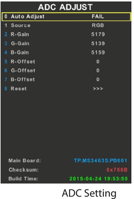

Display Adjustment.
You can use the default values. The default values are average values coming from production.
• Enter SAM mode.
• Select a colour temperature (e.g. COOL, NORMAL, or WARM).
• Set the RED, GREEN and BLUE default values according to the values.
• When finished press OK on the RC, then press STORE to store the aligned values to the NVM.
• Restore the initial picture settings after the alignments.


Option Settings.
The microprocessor communicates with a large number of I2C ICs in the set. To ensure good communication and to make digital diagnosis possible, the microprocessor has to know which ICs to address. The presence / absence of these NT72567 ICs is made known by the option codes.
Notes:
• After changing the option(s), save them by pressing the OK button on the RC before the cursor is moved to the left, select STORE and press OK on the RC.
• The new option setting is only active after the TV is switched “off” / “stand-by” and “on” again with the mains switch (the NVM is then read again).

Reset of Repaired SSB.
A very important issue towards a repaired SSB from a Service repair shop (SSB repair on component level) implies the reset of the NVM on the SSB.
A repaired SSB in Service should get the service Set type “00PF0000000000” and Production code “00000000000000”.
Also the virgin bit is to be set. To set all this, you can use the ComPair tool or use the “NVM editor” and “Dealer options” items in SAM (do not forget to “store”).
After a repaired SSB has been mounted in the set (set repair on board level), the type number (CTN) and production code of the TV has to be set according to the type plate of the set. For this, you can use the NVM editor in SAM. The loading of the CTN and production code can also be done via ComPair.
(Model number programming).
In case of a display replacement, reset the “Operation hours display” to “0”, or to the operation hours of the replacement display.
Remark:
- After the NVM has been replaced, go to SAM and scroll to the <Reload MAC address>
- Select the item and press <OK> on the RC.

Reset of Repaired SSB.
After NVM replacement, reload MAC address via SAM menu. This ensures the correct MAC address to be available in CSM for future repair actions.
Way of working:
• After the NVM has been replaced, go to SAM and scroll to the <Reload MAC address> .
• Select the item and press <OK> on the RC.
Notes:
• Only applicable to all related models that are “Smart TV level 0”enabled (only YouTube access). For models without internet connection feature, no action is needed.
• HDCP keys are located in the NVM. If you are loading NVM with the ComPair tool, there is warning message displayed.
New NVM EEPROMs are shipped with pre-loaded HDCP keys.
SSB Identification.
SSB’s of this chassis are identified by a “715” code on the SSB.
715Axxxx-Nnn-MMM-OOOO
715 main category, Printed Wiring Board
Axxxx sub category, sequential coding number
Nnn Version code
N Development number
nn Production number
MMM Mounting variation code
OOOO Optional variation code
Make sure when replacing an SSB the SSB identification codes match the replacement panel.


Thursday, May 06, 2021

SEMP TCl 50P715. 55P715, 65P715 and 75P715 – how to enter the service mode, software update, power board schematic

 TCL 50P715 127cm (50 Inch) Ultra HD (4K) QLED Smart Android TV

ACCESSING THE FACTORY MENU

Whenever in this manual you request to access the factory menu, the following procedure must be performed:

- Turn on the device;

- On the remote control, press the SETUP key (key) (1);

- Select “Image” option (1);

- Scroll down the options until you find “Advanced Settings” (2) and select;

- Select “Brightness Adjustment” (3);

- Keep the cursor on the “Contrast” option (4)

- On the remote control press the number sequence 9735

Note: Since the original remote control for this model does not have the numeric keys to enter this code, a control of another model of the same brand must be used, in the case of “TCL”, to be able to access the menu of factory.

- Once control is obtained and the sequence is entered, the factory menu will be available.


CHECKING THE SOFTWARE VERSION.

Entering the Factory Menu we can see the version of the software in use:

Main SW update via the User Menu.

- Save the file to the root of a USB device by renaming it as “update.img”.

- With the device disconnected from the mains, connect the USB device, with the installation software, on the USB port.

- Press the TV's Power key and, keeping it pressed, connect the TV to the mains.

- The update will start. After approximately 7 minutes the TV will automatically restart

PROJECT ID update

(If panel information is wrong)

If the screen is completely dark due to the difference in panel x installed software, press 062598 + MENU + xxx (xxx: Panel ID).

In this part, put a note: If the panel used is not included in this list, contact the assistance department technique to obtain the correct ID


After the update, the TV will enter TV mode and the channel that was previously selected.

INTERNET UPDATE

Main Processor

During the update process via the internet, connection failures and even power outages can occur. In these cases the behavior of the device is as follows:

Loss of Internet connection - For download, inform the user and exits the process. Does not compromise the functioning of the TV - Smoothly. The update will continue

Power outage - For download. Does not compromise the functioning of the TV - For the update. Does not compromise the functioning of the TV

PANEL TEST MODE (WARM UP)

Recommended for panel analysis (spots, dots, scratches, etc.).

Enter the Factory Menu as indicated before, choose the option “9-Sita P mode” and turn it on Turn off the TV by the Power key and turn it on again.

Enter the Factory menu again and then select the warm up option. A sequence of screens in different colors where you can check in more detail, possible panel failures.

To EXIT the warm up mode, press the POWER key on the device as the remote control functions will be disabled and if the device is just disconnected from the network, the “warm up” mode will return when is connected to the network again.


Verification of Software Keys

-After turning on the TV with the Sita P mode option on, we will see a frame on the bottom left of the screen with The informations:

In it we can see again the software version, the project ID and the activation keys of the different resources of product:


TENSION TABLE AND SOFTWARE UPDATE

MID: MAC & DID & HDCP & WIDI & WideVine & MGK

MAC (Mac Address) aWithout recording this key, it is not possible to connect to the internet network via ethernet (LAN);

DID: Project identification, already included in the product software,

HDCP without recording this key, high definition images via wireless will not be reproduced;

WIDI without recording this key, image mirroring via wireless will not be reproduced;

Widevine without recording this key, content from YOUTUBE and other sites will not be played;

MGK without recording this key, we will not have access to Netflix content.

IMPORTANT NOTE: If some of the keys are not recorded, the information “NULL” will appear in replace the respective key on that line.  In this case, SEMP TCL support should be contacted for instructions on the recording.

USE TIME INFORMATION

In this model we can check the time of use of the product. Perform the same procedures to enter the Factory Menu, but instead of using the password 9735, enter the code 6425 to enter the Service Menu. In this Menu can be seen on the 9th line the operating time of the device:


Power board schematic diagram