Monday, December 20, 2021

Panasonic TH49EX430M LED TV – how to enter the factory mode, adjustment procedures, audio amplifier schematic and more


Always respect voltages. It makes sense to avoid exposure to electrical shock.  While some sources are expected to have a possible dangerous impact, others of quite high potential are of limited current and are sometimes held in less regard.

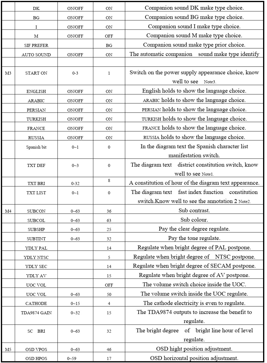
These chassis are designed for Latin America (LA) markets ready for IPTV. The main chip is from Mstar and supports below features matrix.

All tests and measurements mentioned hereafter have to be carried out at a normal mains voltage (100 ~ 240 VAC)
All voltages have to be measured with respect to ground, unless otherwise stated
All final tests have to be done on a complete set including LCD panel in a room with temperature of 25+or-7°C

The Picture Performance assessment such as White Balance (luminance and colour temperature) has to be performed into subdued lighted room after at least 45min of warm-up in order to avoid any temperature drift influence (colorimetry vs time)

Pre-Conditions and DC/DC Check
Before power-on, please check the board according to the relevant block diagram and circuit diagram, and make sure that no serious issue or mistake can destroy the board. 

For example, the output of DC/DC and LDO should not be shorted to ground.
Supply a suited voltage and power-on, then check the voltage according to the relevant block diagram, circuit diagram and voltage spec. The error should less than 5%. 

For example, the voltage for main chip (+3V3, AV3.3, +1V2, CORE1V, etc.), the voltage for DDR (DDRV), the voltage for amplifier (AMP-VCC), etc...

Project ID Modification
There are different ID stored into the NVM depending on different Panels settings and Models features, but there’s only one key branching Project ID that includes all. So, it’s not recommended to modify Panel ID with Hyper terminal as other ID features may not change.
To modify Project ID, you need to go through “Design menu Service menu Project ID”, then spin left or right with RCU “Zoom±” keys to suitable ID (Project name is dynamically refreshed).
 “How to change Project ID with RCU”

Process following subsequence IR codes to change project ID: 062598+MENU+xxx (xxx:Project ID, ex: 003) with TV automatic restart”

Once the boards (chassis, KB, IR, PSU…) and the panel are well interconnected, plug all external generator devices to relevant inputs-outputs below according to their respective test patterns format and check picture content and sound quality accordingly:

Audio tones can be defined by the factory (i.e. 1 KHz & 3 KHz sweep).
Picture video formats can be changed by the factory according to their own standard.

AD Calibration Test

As SoC is built-in an A-D self-calibration mechanism, ADC need not to be performed any more.

DDC & EDID & T-Link Test

The E-EDID data structures are according to VESA Enhanced EDID 1.3 (and EIA-CEA-861B for HDMI). CEA Timing Extension structure has been extended to support all 3D capable timings.
All VGA and HDMI structures have their own BIN profile which are part of main SW and uploaded at power-on into HDMI switch chipset.
For EDID check, it’s needed to check whether the correct EDID is downloaded by checking corresponding EDID NVM Checksum or read them out to check bit by bit if it is in line with the released EDID bin file.

HDCP Test

For HDCP compliancy, it’s needed to check whether the HDCP key has been well set.

Factory Menu 0r (The service mode menu)

Follow the below steps to pop-up the Factory menu in case of “Factory Key” is disabled:
- Press RCU “MENU” key to display main menu
- Select “Setting” and press “OK” key to enter into setting submenu
- Select “Picture” and press “OK” key to enter into picture submenu
- Scroll down to “Contrast” item
- Press the subsequence RCU keys “
9”, “7”, “3” and “5
In case of “Factory Key” is enabled, just press RCU “Return” key to pop-up again the Factory menu.
The status of “Factory Key” can be changed in Factory Menu->Hotkey.
Press RCU “OK” key or “RIGHT” key to enter the submenu.
Press RCU “Menu” key to go back to the root menu.
Press RCU “RIGHT” or “LEFT” key to change the values.
Press RCU “OK” key run the function.
Press RCU “Exit” key exit the Factory menu.

Factory Menu Description

Warm-up

Following TCL standard and practices, it’s required minimum 15min of Warm-Up that can be considered as Burn-In.
Additional Aging for White Balance alignment is no more necessary due to consistent Picture Performance with Cloning usage.
This function is accessible by selecting “Factory menu WARM-UP”, pressing RCU “Zoom+” key and then leaving Factory menu. Other faster methods are available on above enclosed SIACP requirements.

SHOP-END initial

At final process stage, it’s necessary to perform “Reset shop” before any packing to leave
Factory mode and restore User default presets.  This function is accessible by selecting “Factory menu SHOP init”, then pressing RCU “OK” key. Other faster methods are available on above enclosed SIACP requirements

“How to upgrade FLASH SW using USB”

Copy the SW BIN image “V8-S68AT03-LF1VXXX.bin” into USB stick root path.
 “How to upgrade FLASH SW using USB”
Note: If there’s already other “V8-S68AT03-LF1VXXX.bin” into USB root, it needs to be deleted or renamed

Plug USB stick to the TV USB slot.
Press RCU MENUSetting Software upgradeBy USBConfirm.
Or, turn off the TV press and hold the power key of key board before reconnect AC cord to restart TV for 5-8seconds (Forced Upgrade).
When the "UPGRADING SOFTWARE" picture appears, it means TV is uploading SW BIN image. Waiting a few minutes.

When updating is successful, TV should restart automatically.

“How to upgrade MAC Address

Upgrading MAC address need to use the tool in factory and through serial command, the specific methods according to the operation of the factory guidance.

Factory hotkey submenu and Warm-Up Mode submenu

White Balance submenu, Shop init submenu, NVM Reset submenu

Power On Mode submenu, USB UPDATE submenu, Device ID test submenu

“Instructions of Updating SW”

Audio amplifier schematic


Sunday, December 05, 2021

Haier 40DR3505 – How to enter the service mode, How to upgrade the software, Panel failure symptoms – MSD3393LU Chassis


How to enter into Service Mode
The way to the factory mode menu:
Step 1: Press Menu,
Step 2: Press “8893”,
System will be into the factory mode menu when 2 steps above are done.
At the end of the main factory menu, you can see the edition of the software, like this" BUILD TIME 2014-01-21 23:17:21
VERSION v1.0 ”.

How to exit
If you want to exit this factory menu, please press the button ”Exit” on the remote.
System will be out the factory mode menu.

In factory mode menu, press up/down button to choose the up/down item, press right or OK button to the submenu. Press MENU button to go back.

GENERAL SETTING
1) Init Flash;
2) Uart Enable:Choose on or off in Uart Enable;
3) Dbg Message Enable: Choose on or off in Dbg Message Enable;
4) Test Pattern: Choose the Pattern picture;
5) Dynamic Contrast: Choose on or off in Dynamic Contrast;
6) Power On Mode:Choose on or off in Power On Mode;
7) Mirror Control: Choose on or off in Mirror Control;
8) Front End Status
9) Timer Test
10) SSC
11) Erase Flash
12) PQ Advance Debug: Choose on or off in PQ  Advance Debug;
13) Factory remote: Open or close the Factory remote;
14) Factory CH Export.


Adjust the Picture Mode, Picture Curve, White Balance and Over Scan in different source.

SOUND
Adjust the values of Sound Mode, Volume Curve, Audio Output and True Volume in different source.


Panel Setting
1) LVDS Bit Mode: choose the Bit;
2) LVDS MAP: choose the MAP;
3) LVDS ODD/Even: choose ODD or Even;
4) Backlight: Adjust the value of backlight;
5) Reset Panel Setting Date
6) 6MX0 LVDS Map: choose the 6MX0 LVDS MAP;
7)  6MX0 Channel: choose the 6MX0 Channel;
8) 6MX0 Mirror: choose the 6MX0 Mirror;
9) 6MX0 Demo: choose the 6MX0 Demo;
10) 6MX0 Update.


Software update

MSD3393LU software update
1. Copy the software files to a USB disk on the root directory;

2. Insert the USB disk when the AC power is off;
3. Turn on the AC power in turn to begin;
4. Turn off the AC power until the indicator light fast twinkling;
5. Pull out the USB disk and power on the television.
Note:
Do not turn off the TV while it is updating.


1.Mainchip—MSD3393LU(U1)
2. Audio Amplifier—TPA3110D2PWPR (UA1)
3.Main Flash Memory—GD25Q32BSIG (UF1)
4.DC/DC convertor 5V-1.8V for MSD3393LU (U1)—LC1117CLTRAD (UL2)
5.voltage convertor 5V to 3.3V_STB —LC1117CLTR33 (UL1)
6.voltage convertor 5V to 1.15V_STB —LC3406CB5TR (UD1)
7.voltage convertor 5V to 3V for tuner—LC1117CLTR33 (UT1)
8.Tuner —SDCL1005CR33JTDF (RFT1)

Panel failure symptoms


Friday, November 19, 2021

Akai 21CT32 colour TV -How to enter the service mode, full circuit diagram - TDA9381, KA5Q1265, or 5Q0765RT STR, 2SD1866 Horizontal Output Transistor.


Signal process
The main chip is N301 TDA93X1 AV control switch HEF4052, sound driver is N101
N17821A

The TV signal inputs into the tuner (A101) from CABLE or antenna. The pin 10 and pin 11 of the N301 are combined to select the band. The pin 4 of the N301 outputs the PWM tuning signal. The IF video signal comes from the IF pin of the tuner. The 38.9MHz IF signal is coupled to the V308 (pre-amplify) and then to SAWF (Z301). After processed in the SAWF, the 38.9MHz signal gets to the pin 23 and pin 24 of TDA93X1. The IF circuit in TDA93X1 includes such unit as the AGC amplifying
circuit, 38.9MHz oscillator, PLL video demodulator, video amplifier, IF identify circuit and AFT circuit. The demodulated signal (CVBS) comes from the pin 38 of TDA93X1, the sound signal comes from the pin 44.The internal CVBS signal needs norm identification then outputs from the pin 38 of TDA93X1, via the trap-wave circuit (composed of the V351, Z354, Z352) feeds back to the pin 40 of TDA93X1. The RGB signal comes from the pin51, Pin52, Pin53 of TDA93X1, and outputs to the CRT board.
The internal sound signal comes from the pin 44 of TDA93X1, via the coupling capacitor C367 connects to the pin 3 and 5 of TDA9859. The TDA9859 is the audio effect processor, the AN7522N is the driver. The TDA9859 includes bass, treble, balance, surround, effect shortcut options.
Through Synchronous separating circuit, the video signal is divided into horizontal-Synchronizing signal and Vertical-Synchronizing signal. The horizontal-Sync pulse coming from the pin 33 is transferred to the horizontal-drive transistor, and will be used to drive the horizontal-transformer. The horizontal-switch transistor is V451, it and the +B supply drives the fly-back transformer to generate the anode high voltage, the focus voltage, the screen voltage, the CRT board drive voltage 180V, the vertical drive voltage 15V and -15V.
The vertical sawtooth wave is generated on the pin 21 and 22, and then enters the vertical output amplifier circuit. The vertical output amplifier circuit is realized with the power amplifier IC –LA78040.
The TDA8177 is a 7 pins vertical deflection circuit (2 Amperes) for DC-coupled 90° or 110° deflection systems with frame frequencies from 50 up to 120 Hz. Only a single supply voltage for the scan and a second supply for the fly-back are needed.
The vertical drive currents of N301 pins 21 and 22 are connected to input pins 1 and 7 of the TDA8177. The currents are converted into a voltage by resistor R405. Pin 2 is on a fixed DC level (internal bias voltage, about 2.3V) and on pin 1 the drive voltage can be measured (typical 1.4 Vpp). The outputs (pins 4 and 7) are connected to the series connection of the vertical deflection coil and feedback resistor R404 and R406. The voltage across R404 and R406. is fed via pin 1 to obtain a deflection current which is proportional to the drive voltage. The supply voltage for the TDA8177 is 17V at pin 3. The flyback generator has a separate supply voltage of V on pin 6. On pin 4 a vertical guard signal is available. For HF loop stability a damping resistor R407 is connected across the deflection coil.

Power supply [SMPS]
The IC of KA5Q0765RT is adapted in this chassis; it is the product of Fairchild. It supplies four DC voltages, one is the +B
110V, another is Hcc 26V, the third is 13V (the sound drive voltage), the fourth is +16V. The +16V can generate the +8V, +5V and +3.3V by the special generators.

I2C bus control adjustment method: Enter and exit factory mode

With factory remote control – Continuous push [test] key on the remote controller, the TV mode will change as:

Normal > M > BUS OPEN you can select “M” ( factory mode ) or “normal” mode.

2) With user remote control
Push [menu] key display picture manual → push digits key 8500 → display M.
Push [standby] key , exit factory mode and TV will be standby.

Menu-8: Geometrical adjustment .
Receive standard Crosshatch pattern signal for PAL system .

1) Adjust VSLOPE valuethe horizontal line just appear from half bottom shadow.
2) Adjust VSHIFT value
the center horizontal line correspond to CRT vertical center.
3) Adjust Vamp value
to get 90% of vertical picture contents would be displayed on CRT.
4) Adjust HSHIFT value
to get the picture horizontal center correspond to CRT horizontal center.
5) Receive standard Crosshatch pattern signal for NTSC system, and again adjust.

Menu-7: AGC-TOP adjustment
Receive 60dBu (1mv)VH color bar signal adjust AGC value (voltage from high to low), to picture noise reduce gradually to be just disappeared.

MENU9 CRT cut-off and white balance and sub-brightness adjustment.
Receive gray and white 2 steps signal.
a) CRT cut off adjustment.
1. Push [▲P+][▼P-] key to select “SC”, push [►V+][◄V-] key then automatically vertical scan will be stopped.
2. Adjust SCREEN control on Fly-back transformer to get the darkest single horizontal line (red
green or blue, sometimes shows more yellowmore purple or more white).
3. Push [V+][V-] key again, vertical scan work repeat.

b) White balance adjustment

1. Select RD/BD menu.
2. Adjustment RD/BD to get color temperature as x=281, y=311.
c) Sub-brightness adjustment (use stair case signal)
1. Select SB MENU.
2. Adjust SB to get the darkest step being on or off.

MENU6 Set SHIP MODE
Select “SHIPMODE” push [V+][V-]key may be shipped.
Note::
May increase the screen of FBT current, the darking single ought no fly-back line, AV state.

BUS control adjustment item default setting (21 inch)


Note1:
TEXT DEF : TXT_def = 0: Pan_Euro + Cyrillic
= 1: Farsi English + French + Turkish
= 2: Arabic + English + French + Turkish
= 3: UKRAINIAN
Attention:
When TXT_def=0, will appear" the TXT LANGUAGE" in the customer Setup menu, press V+/ V- key," the TXT LANGUAGE" will appear the following circulation: W- TR-> EAST1-> EAST2-> W- TR
The W- TR diagram text includes the following language:
English German Swedish/Fin/Dan/Hungarian Italian French Spanish/Portuguese Turkish
The EAST1 diagram text includes the following language:
Polish German Estonian Slovenian Czech/Slovak Rumanian
The EAST2 diagram text includes the following language:
Polish German Swedish/Fin/Dan/Hungarian Lettish Russian Slovenian Czech/Slovak Estonian
Note 2:
Make use of 4 color keys of the remote control, browse 4 pages of the enactment quickly, namely index function.
The TV/ AV sets the saving key for the index.
While using this function," the TXT LIST" establishes for" ON" in the customer menu.
Example: if want to use the color key of the red quickly 230 pages of enter the diagram text
The sequence press" TEXT"," red key","2","3","0" on the remote control," TV/ AV"
Note 3:
Switch on the hour appearance constitution
0: connect the AC power, enter to need the machine appearance automatically
1: connect the AC power, automatically switch on appearance
2: connect the AC power, if shut down the appearance as the diagram text
appearance, enter the diagram text appearance automatically.

Schematic diagram of the general UOC chassis


Thursday, November 11, 2021

LG LH-T7652SB, LHS-76SBC, LHS-76SBS, LHS-76SBW DVD-CD RECEIVER How to enter the service mode, Schematic diagram, Exploded view


Stereo mode 100W + 100W (Rated Output Power 100W, 4Ω at 1 kHz, THD 10 %)
Surround mode Front: 100W + 100W (Rated Output Power 100W, THD 10 %).  Centre: 100W
Surround: 100W + 100W
(Rated Output Power 100W, 4Ω at 1 kHz, THD 10 %)
Subwoofer: 200W (Rated Output Power 150W, 3Ω at 30 Hz, THD 10 %)

Be sure no power is applied to the chassis or circuit, and observe all other safety precautions

* NTSC model doesn’t have VCR option and use DVD option B~F as VCR option. (only DVD exist)
* PAL model has another separate VCR option. (Both VCR and DVD exist)

1) The pick-up incorporates a strong magnet, and so should never be brought close to magnetic materials.
2) The pick-up should always be handled correctly and carefully, taking care to avoid external pressure and impact. If it is subjected to strong pressure or impact, the result may be an operational malfunction and/or damage to the printed-circuit board.
3) Each and every pick-up is already individually adjusted to a high degree of precision, and for that reason the adjustment point and adjustment screws should absolutely never be touched.
4) Laser beams may damage the eyes.
 Never permit laser beams to enter the eyes.
 NEVER switch ON the power to the laser output part (lens, etc.) of the pick-up if it is damaged.

NEVER look directly at the laser beam, and don’t let contact fingers or other exposed skin.

Cleaning the lens surface
If there is dust on the lens surface, the dust should be cleaned away by using an air bush (such as used for camera lens). The lens is held by a delicate spring. When cleaning the lens surface, therefore, a cotton swab should be used, taking care not to distort this.  Never attempt to disassemble the pick-up spring by excess pressure. If the lens is extremely dirty, apply isopropyl alcohol to the cotton swab.
(Do not use any other liquid cleaners, because they will damage the lens.) Take care not to use too much of this alcohol on the swab, and do not allow the alcohol to get inside the pick-up.

Service mode entry for EEPROM

SMPS Schematic

Main board schematic


Cabinet and mainframe Exploded View


Sunday, October 31, 2021

Samsung HT-F4500 5.1CH Blu-ray Home Entertainment System- amplifier and SMPS schematic, How to insert the region code

 How to check the firmware version, How to update the firmware, How to initialize the set, Disassemble procedure, amplifier and SMPS schematic, How to insert the region code - Samsung HT-F4500  5.1CH Blu-ray Home Entertainment System

Disassembly

1. Unfasten 3 screws on the back and 2 on the sides.
Back : BH,+,B,M3,L10,ZPC(BLK),SWRCH18A
Side : BH,+,B,M3,L8,ZPC(BLK),SWRCH18A

2. Lift the top cover

3. Disconnect 2 FFC cables from deck and SMPS wire and fan wire and FFC cable from front assy.
Unfasten 3 screws on the Main PCB.
: BH,+,B,M3,L6,ZPC(WHT),SWRCH18A

4. Three screws on the back side.
: BH,+,B,M3,L10,ZPC(BLK),SWRCH18A

5. Disassemble and lift Main PCB

6. Lift up on the 3 hooks connecting the COVER-FRONT to the COVER-BOTTOM

7. Lift the 2 hooks on the side of the COVER-FRONT

To remove the FRONT-COVER all hooks must be disconnect at the same time and you should lift from the bottom and pull Up and away from the device.

8. The 4 hooks on the top will be loosened as you lift the FRONT-COVER from the bottom

9.  Unfasten 3 screws on the Front PCB.
: BH,+,B,M3,L10,ZPC(BLK),SWRCH18A

10. Unfasten the Assy-Deck by pushing the locking points on the side

11. Unfasten 5 screws on the SMPS

12. Unfasten 3 screws on the back side.
: BH,+,B,M3,L10,ZPC(BLK),SWRCH18A)
Remove the SMPS and Fan.

How to check F/W version

Method 1
- Step 1: Open the tray.
- Step 2: Press and hold “INFO” button on the remote for 5 seconds.
- Then, you will see below screen.

Method 2 (For only Back End version)
- Select Settings from the Home Screen.
- Support→ Contact Samsung
Description for the meaning
- Front : System micom
- S/W : BACKEND Firmware
- Loader : Loader Firmware
- Region : BD region code / DVD region code
- Model : Model name

How to update firmware

The Software Upgrade menu allows you to upgrade the product’s software for performance improvements or additional services.
Never turn the product off or back on manually during the update process.
1) In the Home menu, select Settings, and then press the ENTER button.
2) Select Support, and then press the ENTER button.
3) Select Software Upgrade, and then press the ENTER button.
4) Select one of the following methods:
By Online
By USB
Auto Upgrade Notification
5) Press the ENTER button. Directions for each method begin below.

The update is complete when the product turns off after restarting. Press the POWER button to turn on the updated product for your use. Never turn the product on or off manually during the update process.
• Samsung Electronics takes no legal responsibility for product malfunction caused by an unstable Internet connection or consumer negligence during a software upgrade.
• If you want to cancel the upgrade while the upgrade software is downloading, press the ENTER button.

[Never turn the product off or back on manually during the update process]

By Online

Your product must be connected to the Internet to use the By Online function. Remove all discs before you begin.
1) Select By Online, and then press the ENTER button. The Connecting to Server message appears.
2) If an update is available, a popup message appears asking if you want to upgrade. If you select Yes, the product turns off automatically, turns on, and then begins the upgrade.
 IMPORTANT
– Never turn the home theater on or off manually during a software upgrade.
3) The update progress popup appears. When the update is completed, the product turns off automatically again.
4) Press the POWER button to turn on the product.

The update is complete when the product turns off after restarting. Press the POWER button to turn on the updated product for your use.
• Never turn the product off or on manually during the update process.
• Samsung Electronics takes no legal responsibility for a product malfunction caused by an unstable internet connection or consumer negligence during software upgrade.

By USB
1) Visit www.samsung.com.
2) Click SUPPORT on the top right of the page.
3) Enter the product's model number into the search field, and then click Find Product.
4) Click Get downloads in the center of the page below the Downloads header.
5) Click Firmware in the center of the page.
6) Click the ZIP icon in the File column on the right side of the page.
7) Click OK in the pop-up that appears to download and save the firmware file to your PC.
8) Unzip the zip archive to your computer. You should have a single folder with the same name as the zip file.
9) Copy the folder to a USB flash drive.
10) Make sure no disc is inserted in the product, and then insert the USB flash drive into the USB port of the product.
11) In the product’s menu, go to Settings > Support > Software Upgrade.
12) Select By USB

There should be no disc in the product when you upgrade the software using the USB Host jack.
Never turn the product off or on manually during the update process.
When the software upgrade is done, check the software details in the Software Upgrade menu

Auto Upgrade Notification
If your product is connected to the network and you set Auto Upgrade Notification on, the product will notify you if a new software version is available with a pop-up message.
1) Turn on the product.
2) Press the ▲▼ buttons to move Settings > Support > Software update.
3) In the Software Upgrade menu, set Auto Upgrade Notification to On.
If there is a new software version available, the product will notify you with a pop-up message.
4) To upgrade the firmware, select Yes. The product turns off automatically, turns on, and then begins the upgrade.
5) The update progress popup will appear. When the update is complete, the product will turn off automatically again.
6) Press the POWER button to turn on the product

The update is complete when the product turns off after restarting. Press the POWER button to turn on the updated product for your use. Never turn the product on or off manually during the update process.
Samsung Electronics shall take no legal responsibility for product malfunction caused by unstable of internet connection or consumer negligence during software upgrade.

How to initialize the set [Cold Start Method]

1 ) This is useful for forgotten Parental Lock password.
2) It is possible to initialize B/END and System Micom at same time.
Method
1) Press “■” button on the front panel for over 5 seconds while ‘no disc’ status.
2) Then, VFD sign : “INIT” → Power will be turned off automatically

How to set the country region code

Inserting the Region Code after replacing the Main PCB

When replacing the MAIN PCB Ass’y, system micom IC(UIC1) should have proper region code.
The Set is not working properly if you don’t insert Region code.
The region code can be inserted by the remote control.

1.Change function mode to "AUX".
2. Press and hold "Tuner Memory" on the remote control for 4-5 seconds

3. The VFD will now say "T-MODE", you must quickly press the "▼" button during T-Mode status.

4. The VFD will now say TEST – – , now insert 46

5. The VFD will now read – – –. Insert the correct Region code based on the table below.
Ex: For USA Buyers you will type in 0 2 0


Wiring diagram

Pin connections of connectors

Amplifier and SMPS schematic