Signal process
The main chip is N301 TDA93X1 AV control switch HEF4052, sound driver is N101
N17821A
The
TV signal inputs into the tuner (A101) from CABLE or antenna. The pin 10 and
pin 11 of the N301 are combined to select the band. The pin 4 of the N301
outputs the PWM tuning signal. The IF video signal comes from the IF pin of the
tuner. The 38.9MHz IF signal is coupled to the V308 (pre-amplify) and then to
SAWF (Z301). After processed in the SAWF, the 38.9MHz signal gets to the pin 23
and pin 24 of TDA93X1. The IF circuit in TDA93X1 includes such unit as the AGC
amplifying
circuit, 38.9MHz oscillator, PLL video demodulator, video amplifier, IF
identify circuit and AFT circuit. The demodulated signal (CVBS) comes from the
pin 38 of TDA93X1, the sound signal comes from the pin 44.The internal CVBS
signal needs norm identification then outputs from the pin 38 of TDA93X1, via
the trap-wave circuit (composed of the V351, Z354, Z352) feeds back to the pin
40 of TDA93X1. The RGB signal comes from the pin51, Pin52, Pin53 of TDA93X1,
and outputs to the CRT board.
The internal sound signal comes from the pin 44 of TDA93X1, via the coupling
capacitor C367 connects to the pin 3 and 5 of TDA9859. The TDA9859 is the audio
effect processor, the AN7522N is the driver. The TDA9859 includes bass, treble,
balance, surround, effect shortcut options.
Through Synchronous separating circuit, the video signal is divided into horizontal-Synchronizing
signal and Vertical-Synchronizing signal. The horizontal-Sync pulse coming from
the pin 33 is transferred to the horizontal-drive transistor, and will be used
to drive the horizontal-transformer. The horizontal-switch transistor is V451,
it and the +B supply drives the fly-back transformer to generate the anode high
voltage, the focus voltage, the screen voltage, the CRT board drive voltage
180V, the vertical drive voltage 15V and -15V.
The vertical sawtooth wave is generated on the pin 21 and 22, and then enters
the vertical output amplifier circuit. The vertical output amplifier circuit is
realized with the power amplifier IC –LA78040.
The TDA8177 is a 7 pins vertical deflection circuit (2 Amperes) for DC-coupled
90° or 110° deflection systems with frame frequencies from 50 up to 120 Hz.
Only a single supply voltage for the scan and a second supply for the fly-back
are needed.
The vertical drive currents of N301 pins 21 and 22 are connected to input pins
1 and 7 of the TDA8177. The currents are converted into a voltage by resistor
R405. Pin 2 is on a fixed DC level (internal bias voltage, about 2.3V) and on
pin 1 the drive voltage can be measured (typical 1.4 Vpp). The outputs (pins 4
and 7) are connected to the series connection of the vertical deflection coil
and feedback resistor R404 and R406. The voltage across R404 and R406. is fed
via pin 1 to obtain a deflection current which is proportional to the drive
voltage. The supply voltage for the TDA8177 is 17V at pin 3. The flyback
generator has a separate supply voltage of V on pin 6. On pin 4 a vertical guard
signal is available. For HF loop stability a damping resistor R407 is connected
across the deflection coil.
Power
supply [SMPS]
The IC of KA5Q0765RT is adapted in this chassis; it is the product of
Fairchild. It supplies four DC voltages, one is the +B= 110V, another
is Hcc= 26V, the third is 13V (the sound drive voltage), the fourth is
+16V. The +16V can generate the +8V, +5V and +3.3V by the special generators.
I2C bus control
adjustment method: Enter and exit factory mode
With factory remote control – Continuous push [test]
key on the remote controller, the TV mode will change as:
Normal
> M > BUS OPEN you can select “M” ( factory mode ) or “normal” mode.
2)
With user remote control
Push [menu] key → display picture manual → push digits key 8500 → display M.
Push [standby] key , exit
factory mode and TV will be standby.
Menu-8: Geometrical
adjustment .
Receive standard Crosshatch pattern signal for PAL system .
1) Adjust VSLOPE value, the
horizontal line just appear from half bottom shadow.
2) Adjust VSHIFT value, the center horizontal line correspond to CRT vertical center.
3) Adjust Vamp value, to get 90% of vertical picture contents would be displayed on CRT.
4) Adjust HSHIFT value, to get the picture horizontal center correspond to CRT horizontal
center.
5) Receive standard Crosshatch pattern signal for NTSC system, and again
adjust.

Menu-7: AGC-TOP
adjustment
Receive
60dBu (1mv)VH color bar signal, adjust AGC value (voltage from high to low), to picture
noise reduce gradually to be just disappeared.
MENU9 CRT cut-off and
white balance and sub-brightness adjustment.
Receive
gray and white 2 steps signal.
a) CRT cut off adjustment.
1. Push [▲P+][▼P-] key to select “SC”, push [►V+][◄V-] key then automatically
vertical scan will be stopped.
2. Adjust SCREEN control on Fly-back transformer to get the darkest single
horizontal line (red green or blue, sometimes shows
more yellow, more purple or more white).
3. Push [V+][V-] key again, vertical scan work repeat.
b) White balance
adjustment
1. Select RD/BD menu.
2. Adjustment RD/BD to get color temperature as x=281, y=311.
c)
Sub-brightness
adjustment (use stair case signal)
1. Select SB MENU.
2. Adjust SB to get the darkest step being on or off.
MENU6 Set SHIP MODE
Select
“SHIPMODE”, push [V+][V-]key may be shipped.
Note::
May increase the screen of FBT current, the darking single ought no fly-back
line, AV state.
BUS control adjustment
item default setting (21 inch)

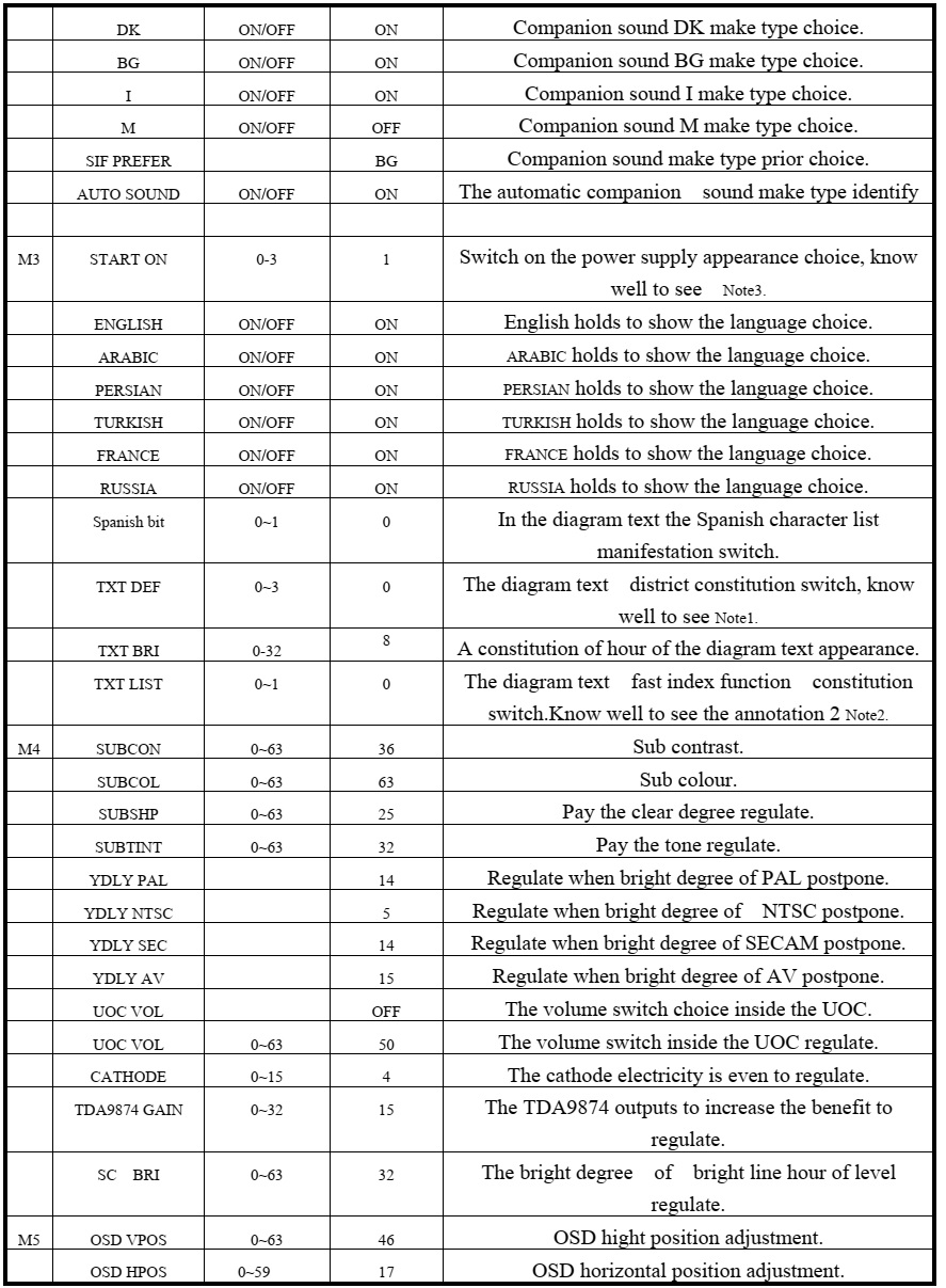

Note1:
TEXT DEF : TXT_def = 0: Pan_Euro + Cyrillic
= 1: Farsi English + French + Turkish
= 2: Arabic + English + French + Turkish
= 3: UKRAINIAN
Attention:
When TXT_def=0, will appear" the TXT LANGUAGE" in the customer Setup
menu, press V+/ V- key," the TXT LANGUAGE" will appear the following
circulation: W- TR-> EAST1-> EAST2-> W- TR
The W- TR diagram text includes the following language:
English German Swedish/Fin/Dan/Hungarian Italian French Spanish/Portuguese
Turkish
The EAST1 diagram text includes the following language:
Polish German Estonian Slovenian Czech/Slovak Rumanian
The EAST2 diagram text includes the following language:
Polish German Swedish/Fin/Dan/Hungarian Lettish Russian Slovenian Czech/Slovak
Estonian
Note 2:
Make use of 4 color keys of the remote control, browse 4 pages of the enactment
quickly, namely index function.
The TV/ AV sets the saving key for the index.
While using this function," the TXT LIST" establishes for"
ON" in the customer menu.
Example: if want to use the color key of the red quickly 230 pages of enter the
diagram text
The sequence press" TEXT"," red
key","2","3","0" on the remote
control," TV/ AV"
Note 3:
Switch on the hour appearance constitution
0: connect the AC power, enter to need the machine appearance automatically
1: connect the AC power, automatically switch on appearance
2: connect the AC power, if shut down the appearance as the diagram text
appearance, enter the diagram text appearance automatically.
Schematic diagram of the general UOC chassis

No comments:
Post a Comment