Tuesday, March 30, 2021

Philips HTS 5540, HTS 5550 – factory setting, password change, upgrading the software, shematic diagram - DVD Home Theater System


System, Region Code, etc. Setting Procedure


Restore factory setting

a)Press <SETUP> button on R/C
b) Select <preference setup> ,then press < OK >
c) Select <default>, then press <OK> to confirm.

Version control change
a) Open the Door , and then press “1” “5” “9” on RC.
b) Press <OK> button on RC.
c) TV will show message as follow:

Password change
a) Press <SETUP> button on R/C.
b) Select <preference setup> , and then press <OK>
c) Select <password> <change> and then press <OK> to confirm.
(“
0000” is default password supplied.)

Trade model
a) Press <Open/Close> button on R/C.
b) Press “
2” “5” “9” on R/C,VFD will display “TRA ON “ or “TRA OFF“

Check on software version
a) Press <SETUP> button on R/C.
b) Select <preference setup> and then press <OK>
c) Select <version info> and itthen press <OK>
d) TV will show message as follow:

Upgrading new software
a) Copy the latest upgrading software onto a CD-R or USB storage device.
b) Insert the CD-R program disc or connect the USB storage device to the home theater.
c) TV will show relevent message.

d) Select <OK>,the home theater will start to upgrading automatically.
Note: when upgrade in progress, please do not unplug or switch off the device.  When the updated is complete, the home theater automatically switch to standby.

[Only a qualified service person should reprogram the Region Code.]

Wiring diagram


Display board schematic and PWB


Circuit diagram [Schematic]


Power supply [SMPS] schematic and PWB


TAS 5152: Digital power amplifier schematic


Monday, March 15, 2021

KUBO LCD TV – Hitachi 32HB4T62 - Hitachi 32290DLBN – Vestel 17IPS62 – MB82S troubleshooting – Service Mode - Schematic diagram


No sound, LED blinking, standby ON/OFF, 
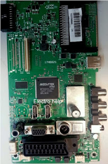
No signal. Service menu settings – Vestel 17IPS62, Vestel MB82S

AUDIO AMPLIFIER-TAS5721 (optional)

 The TAS5721 is a 15-W stereo or 2x10 W + 1x15 W2.1 device, efficient, digital audio-power amplifier for driving stereo bridge-tied speakers. One serial data input allows processing of up to two discrete audio channels and seamless integration to most digital audio processors and MPEG decoders. The device accepts a wide range of input data and data rates. A fully programmable data path routes these channels to the internal speaker drivers. The TAS5721 is a slave-only device receiving all clocks from external sources. The TAS5721 operates with a PWM carrier between a 384-kHz switching rate and a 352-KHz switching rate, depending on the input sample rate. Oversampling combined with a fourth- order noise shaper provides a flat noise floor and excellent dynamic range from 20 Hz to 20 kHz.

Audio Input-Output
– 15Wx2 into 8Ω
– Supports Single Device 0.1, 2.0, 2.1 Modes
– Wide PVDD Range, From 4.5 V to 26 V Performance
– Efficient Class-D Operation Eliminates Need for Heatsinks
– Requires Only 3.3 V and PVDD
– One Serial Audio Input (Two Audio Channels)
– I2C Address Selection via PIN (Chip Select)
– Supports 8-kHz to 48-kHz Sample Rate (LJ/RJ/I2S)
– External Headphone-Amplifier Shutdown Signal
– Integrated CAP
Free Headphone Amplifier
– Stereo Headphone (Stereo 2
V RMS Line Driver) Outputs
• Audio/PWM Processing
– Independent Channel Volume Controls With The 24-dB to Mute
– Separate Dynamic Range Control for Satellite and Sub Channels
– 21 Programmable Biquads for Speaker EQ
– Programmable Coefficients for DRC Filters
– DC Blocking Filters
– Support for 3D Effects
• General Features
– Serial Control Interface Operational Without MCLK
– Factory-Trimmed Internal Oscillator for Automatic Rate Detection
– Surface Mount, 48-Pin, 7-mm × 7-mm HTQFP Package
– Thermal and Short-Circuit Protection

POWER STAGE

The DC voltages required at various parts of the chassis and panel are provided by a main power supply unit. MB82S chassis can operate with PW05, IPS60, IPS70, IPS16, IPS17, IPS19, PW25, PW26, PW82-3, PW03, PW04, PW06, PW07 as main power supply and also with 12V adaptor.
Which power board can be used for board to board or cable connection?
Board to board (BTB) : PW05, IPS60, IPS70, IPS16, IPS17, IPS19
Power Cable : PW25, PW26, PW82-3, PW03, PW04, PW06, PW07
The power supplies generate 24V, 12V, 5V, 3,3V and 12V, 5V, 3.3V stand by mode DC voltages. Power stage which is on-chassis generates 5V, 3V3 stand by voltage and 12V, 8V, 5V, 3V3, 2.5V, 1,8V and 1,2V supplies for other different parts of the chassis.
 For PW26 and PW27 just common blocks are enough for proper operation.
Short CCT Protection Circuit
Short circuit protection is necessary for protecting chassis and main IC against damages when any Vcc supply shorts to ground. Protect pin should be logic high while normal operation. When there is a short circuit protect pin should be logic low. After any short detection, SW forces LEDs on LED card to blink.

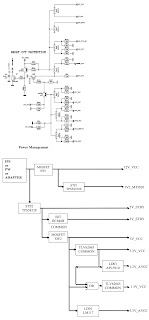
Panel Supply Switch Circuit
This switch is used to open and close panel supply of TCON. It is controlled by port of main u-controller. Also with this circuit panel sequence could be adjusted correctly. 3 panel supplies are connected to this circuit. All of them are optional according to panels.

SERVICE MENU SETTINGS
In order to reach service menu, First Press “MENU” Then press the remote control code two times, which is “4725”.
In first screen following items can be seen (MB8x is same as MB6x service menu):

USB Operations
USB operations option can not be used directly. It can be used for updating panel tool, hw configuration etc.

SOFTWARE UPDATE
In MB82 project there is only one software. From following steps software update procedure can be seen:
1. MB82.bin directly inside of a flash memory (not in a folder).
2. Put flash memory to the TV when TV is powered off.
3. Power ON the and OK button on the remote control when the TV is opened.
4. If First Time Installation screen comes, it means software update procedure is successful.

TROUBLESHOOTING: No Backlight Problem
Problem: If TV is working, led is normal and there is no picture and backlight on the panel.
Possible causes: Backlight pin, dimming pin, backlight supply, stby on/off pin Backlight pin should be high in open position. If it is low, please check Q30 and panel cables.

Dimming pin should be high or square wave in open position. If it is low, please check S16 for Mstar side and panel or power cables, connectors.

Backlight power supply should be in panel specs. Please check CN4 for MB82, related connectors for power supply cards.


CI Module Problem
Problem: CI is not working when CI module inserted.
Possible causes: Supply, supply control pin, detect pins, mechanical positions of pins CI supply should be 5V when CI module inserted. If it is not 5V please check CI-POWER-CTRL, this pin should be low.

Please check mechanical positions of CI module.
Detect ports should be low. If it is not low please check CI connector pins, CI module pins and 3V3-VCC on MB82.

Led Blinking Problem
Problem: LED blinking, no other operation
This problem indicates a short on Vcc voltages. Protect pin should be logic high while normal operation. When there is a short circuit protect pin will be logic low. If you detect logic low on protect pin, unplug the TV set and measure the control voltage points with a multimeter to find the shorted voltage to ground.

No Sound Problem
Problem: No audio at main TV speaker outputs.
Check supply voltages of VDD-AUDIO, 5V-VCC or 12V-VCC with a voltage-meter.
There may be a problem in headphone connector or headphone detect circuit (when headphone is connected, speakers are automatically muted). Measure voltage at HP-DETECT pin, it should be 3.3v.

No Sound Problem at Headphone
Problem: No audio at headphone output.
Check HP detect pin, when headphone is. Check 5V-VCC and 3V3-VCC with a voltage meter.

Standby On/Off Problem
Device cannot boot, TV hangs in standby mode.
There may be a problem about power supply. Check 12V-VCC, 5V-VCC and 3V3-VCC with a voltage-meter. Also there may be a problem about SW. Try to update TV with latest SW. Additionally it is good to check SW printouts via hyper-terminal (or Tera term). These printouts may give a clue about the problem.

No Signal Problem
Problem: No signal in TV mode.
Check tuner supply voltage; 3V3-TUN. Check tuner options are correctly set in Service menu. Check AGC voltage at IF-AGC pin of tuner.

Schematic diagram


Sunday, March 07, 2021

How to disassemble Mitsubishi Air-conditioner-MUZ SF25VE, MUZ SF42EV


Applicable to: Mitsubishi Airconditioners  MUZ-SF25VE MUZ-SF25VEH MUZ-SF35VE MUZ-SF35VEH MUZ-SF42VE MUZ-SF42VEH

DISASSEMBLY INSTRUCTIONS

<"Terminal with locking mechanism" Detaching points>
The terminal which has the locking mechanism can be detached as shown below.
There are two types (refer to (1) and (2)) of the terminal with locking mechanism.
The terminal without locking mechanism can be detached by pulling it out.
Check the shape of the terminal before detaching.


Removing the cabinet
(1) Remove the screw fixing the service panel.
(2) Pull down the service panel and remove it.
(3) Disconnect the power supply and indoor/outdoor connecting wire.
(4) Remove the screws fixing the top panel.
(5) Remove the top panel.
(6) Remove the screws fixing the cabinet.
(7) Remove the cabinet.
(8) Remove the screws fixing the back panel.
(9) Remove the back panel.


Removing the inverter assembly, inverter P.C. board
(1) Remove the cabinet and panels. (Refer to 1.)
(2) Disconnect the lead wire to the reactor and the following connectors:
<Inverter P.C. board>
CN721 (R.V. coil)
CN722 (Defrost heater) MUZ-SF25/35/42VEH
CN931, CN932 (Fan motor)
CN641 (Defrost thermistor and discharge temperature thermistor)
CN643 (Ambient temperature thermistor)
CN644 (Outdoor heat exchanger temperature thermistor)
CN724 (LEV)
(3) Remove the compressor connector (CN61).
(4) Remove the screws fixing the heat sink support and the separator.
(5) Remove the fixing screws of the terminal block support and the back panel.
(6) Remove the inverter assembly.
(7) Remove the screw of the earth wire and screw of the terminal block support.
(8) Remove the heat sink support from the P.C. board support.
(9) Remove the screw of the inverter P.C. board and remove the inverter P.C. board from the P.C. board support.

Removing R.V. coil
(1) Remove the cabinet and panels. (Refer to 1.)
(2) Disconnect the following connectors:
<Inverter P.C. board>
CN721 (R.V. coil)
(3) Remove the R.V. coil.

Removing the discharge temperature thermistor, defrost thermistor, outdoor heat exchanger temperature thermistor and ambient temperature thermistor
(1) Remove the cabinet and panels. (Refer to 1.)
(2) Disconnect the lead wire to the reactor and the following connectors:
<Inverter P.C. board>
CN641 (Defrost thermistor and discharge temperature thermistor)
CN643 (Ambient temperature thermistor)
CN644 (Outdoor heat exchanger temperature thermistor)
(3) Pull out the discharge temperature thermistor from its holder.
(4) Pull out the defrost thermistor from its holder. (Photo 6)
(5) Pull out the outdoor heat exchanger temperature thermistor from its holder.
(6) Pull out the ambient temperature thermistor from its holder.


Removing outdoor fan motor
(1) Remove the cabinet and panels. (Refer to 1.)
(2) Disconnect the following connectors:
<Inverter P.C. board>
CN931, CN932 (Fan motor)
(3) Remove the propeller nut.
(4) Remove the propeller.
(5) Remove the screws fixing the fan motor.
(6) Remove the fan motor.

Removing the compressor and 4-way valve
(1) Remove the cabinet and panels. (Refer to 1.)
(2) Remove the inverter assembly. (Refer to 2.)
(3) Recover gas from the refrigerant circuit.
NOTE: Recover gas from the pipes until the pressure gauge shows 0 kg/cm2 (0 MPa).
(4) Detach the brazed part of the suction and the discharge pipe connected with compressor.
(5) Remove the nuts of compressor legs.
(6) Remove the compressor.
(7) Detach the brazed part of pipes connected with 4-way valve.

Removing the cabinet
(1) Remove the screws of the service panel.
(2) Remove the screws of the top panel.
(3) Remove the screw of the valve cover.
(4) Remove the service panel.
(5) Remove the top panel.
(6) Remove the valve cover.
(7) Disconnect the power supply and indoor/outdoor connecting wire.
(8) Remove the screws of the cabinet.
(9) Remove the cabinet.
(10) Remove the screws of the back panel.
(11) Remove the back panel.

Removing the inverter assembly, inverter P.C. board
(1) Remove the cabinet and panels. (Refer to 1.)
(2) Disconnect the lead wire to the reactor and the following connectors:
<Inverter P.C. board>
CN721 (R.V. coil)
CN722 (Defrost heater) MUZ-SF50VEH
CN931, CN932 (Fan motor)
CN641 (Defrost thermistor and discharge temperature thermistor)
CN643 (Ambient temperature thermistor)
CN644 (Outdoor heat exchanger temperature thermistor)
CN724 (LEV)
(3) Remove the compressor connector.
(4) Remove the screws fixing the heat sink support and the separator.
(5) Remove the fixing screws of the terminal block support and the back panel.
(6) Remove the inverter assembly.
(7) Remove the screw of the earth wire, screw of the P.C. board cover and screws of the terminal block support.
(8) Remove the heat sink support from the P.C. board support.
(9) Remove the screw of the inverter P.C. board and the inverter P.C. board from the P.C. board support.

Removing R.V. coil
(1) Remove the cabinet and panels. (Refer to 1.)
(2) Disconnect the following connector:
<Inverter P.C. board>
CN721 (R.V. coil)
(3) Remove the R.V. coil.

Removing the discharge temperature thermistor, defrost thermistor, outdoor heat exchanger temperature thermistor and ambient temperature thermistor
(1) Remove the cabinet and panels. (Refer to 1.)
(2) Disconnect the lead wire to the reactor and the following connectors:
<Inverter P.C. board>
CN641 (Defrost thermistor and discharge temperature thermistor)
CN643 (Ambient temperature thermistor)
CN644 (Outdoor heat exchanger temperature thermistor)
(3) Pull out the discharge temperature thermistor from its holder.
(4) Pull out the defrost thermistor from its holder.
(5) Pull out the outdoor heat exchanger temperature thermistor from its holder.
(6) Pull out the ambient temperature thermistor from its holder.

Removing outdoor fan motor
(1) Remove the top panel, cabinet and service panel. (Refer to 1.)
(2) Disconnect the following connectors:
<Inverter P.C. board>
CN931 and CN932 (Fan motor)
(3) Remove the propeller nut.
(4) Remove the propeller.
(5) Remove the screws fixing the fan motor.
(6) Remove the fan motor.

Removing the compressor and 4-way valve
(1) Remove the top panel, cabinet and service panel. (Refer to 1.)
(2) Remove the back panel. (Refer to 1.)
(3) Remove the inverter assembly. (Refer to 2.)
(4) Recover gas from the refrigerant circuit.
NOTE: Recover gas from the pipes until the pressure gauge shows 0 kg/cm2 (0 MPa).
(5) Detach the brazed part of the suction and the discharge pipe connected with compressor.
(6) Remove the compressor nuts.
(7) Remove the compressor.
(8) Detach the brazed part of 4-way valve and pipe.


Saturday, March 06, 2021

Hitachi 26LD6600, 32LD6600, 37LD6600, 26LD6600A, 32LD6600A, 37LD6600A, 32LD6600B Power supply (SMPS) circuit diagram, How to enter the service mode


Main PWB: Vestel 17MB08, 17MB15

Service menu

To enter the service menu, first enter the MENU by pressing MENU button and then press the digit 4, 7, 2 and 5 respectively.

Picture adjust: source:  all possible sources given with the chassis as list.

Mode:  three items as a list; Natural, Dynamic, Cinema

Color temp:  three items as a list; Cool, Normal, Warm.

Contrast:  slider bar.  Changing value between 0 and 63.

Brightness: slider bar.  Changing value between 0 and 63.

Sharpness:  slider bar.  Changing value between 0 to 31.

Color: slider bar.  Changing the value between 0 to 99.

R:  slider bar. Changing the value between 0 to 31.

G:  slider bar.  Changing the value between 0 to 31.

B:  slider bar.  Changing the value between 0 to 31.

Backlight:  slider bar.  Changing the value between 0 to 255.

In this menu preset values for each mode (contrast, brightness, sharpness, color values for each mode NATURAL, DYNAMIC, CINEMA and for each color temp: R, G, B values for each color temp- COOL, NORMAL, WARM are determined for each source.

Block diagram

PCB layout


RESONANT MODE TFT POWER SUPPLY: 26, 32 and 37 inch Hitachi LCD TVs