Monday, September 28, 2020

Sharp XV Z90U. Sharp DT 200 DMD Projector – how to disassemble, how to reset the lamp


This SHARP projector uses a DMD chip. This very sophisticated chip contains 480,000 pixels. As with any high technology electronic equipment such as large screen TVs, video systems and video cameras, there are certain acceptable tolerances that the equipment must conform to.

This unit has some inactive pixels within acceptable tolerances which may result in inactive dots on the picture screen. This will not affect the picture quality or the life expectancy of the unit.

Service work should be performed only by qualified service technicians who are thoroughly familiar with all safety checks and servicing guidelines.

Be sure to wear sun-glasses when servicing the projector with the lamp turned “on” and the top enclosure removed.

Lamp Replacement

Note:

Since the lamp reaches a very high temperature during units operation replacement of the lamp should be done at least one hour after the power has been turned off. (to allow the lamp to cool off.)

Installing the new lamp, make sure not to touch the lamp (bulb) replace the lamp by holding its reflector.

[Never turn the power on without the lamp to avoid electric-shock or damage of the devices since the stabilizer generates high voltages at its start.]

Connection Pin Assignments

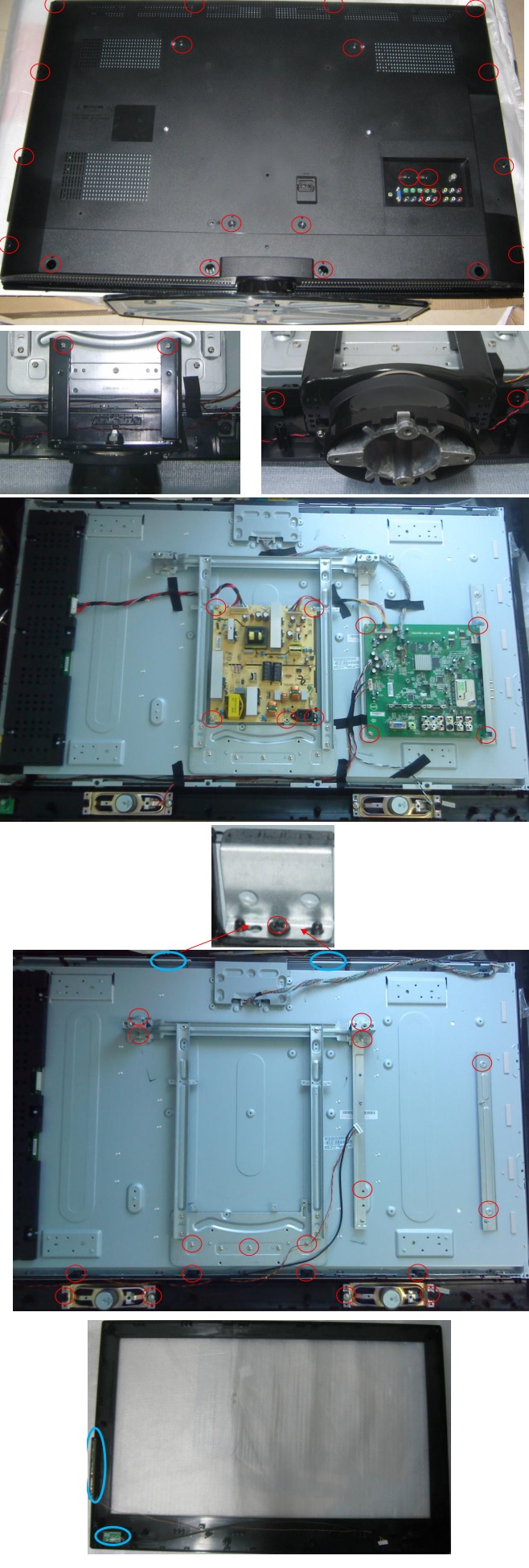
REMOVING OF MAJOR PARTS

Removing the swivel stand and the lamp box.

1-1. Remove lock lever, and remove the swivel stand.

1-2. Loosen 1 scrwew, and remove the lamp door .

1-3. Loosen 3 screws, and take out a lamp box.

Removing the side covers and the top body.

2-1. Push front end of the side cover from bottom, and remove a hook.

2-2. Pull the side cover in the direction of the arrow, and remove it.

2-3. Remove 6 screws and 1connector, and remove a top body.

Removing the main PWB.

3-1. Remove 6 screws.

3-2. Remove each connector on the main PWB.

Removing the power unit.

4-1. Remove each connector on the power PWB.

4-2. Remove 2 screws, and remove the power unit fan.

4-3. Remove 3 screws, and take out the power unit assembly.

4-4. Remove 4 screws, and remove power shield.

Removing the Ballast unit.

5-1. Remove lens shift knob.

5-2. Remove 2 screws, and remove the ballast socket.

5-3. Remove 3 screws, and remove the ballast unit.

5-4. Remove shielding plate, and remove 2 connectors on the ballast PWB.

5-5. Remove 2 screws, and remove ballast PWB.

Removing the optic mechanism unit.

6-1. Remove a connector.

6-2. Remove 6 screws, and remove the optic mechanism Unit

Removing the each other PWBs.

7-1. Remove 1 screw, and remove front R/C receiver PWB unit .

7-2. Remove 1 screw, and remove LED PWB unit.

7-3. Remove 1 screw, and remove a terminal-2 PWB unit.

7-4. Remove 2 screws, and remove an AC socket.

7-5. Remove 1 screw, and remove rear R/C receiver PWB unit.

7-6. Remove 1 screw, and remove DVI-TAN1 PWB unit.

Removing the formatter PWB.  Removing the formatter PWB.

Precautions in replacing the DMD chip

Note: Be careful not to allow dust and fingerprint on the cover glass of DMD chip and prism surface of optical engine.

1. When you fix 4screws of backer plate assembly, press backer plate to formatter PWB and fix by cross multiply step by step.

2. If something shade appears on the projection screen like Fig1, release 2 screws on mirror adjusting plate and move that plate to adjust illumination area of DMD chip.

Precautions in setting up the DMD (Digital Micro mirror Device) unit

Before connecting the formatter PWB to the optical engine, take the following steps. Look at the voltage rank marking that is on the DMD itself. Referring to this marking, set the DIP switches on the formatter PWB. And connect this PWB to the optical engine. Wrong settings will adversely affect the system performance.

Outline of the optical unit

Distinction between long and short focal length lens

• Long focal length lens: focus ring width: about 18 mm > XV-Z90U

• Short focal length lens: focus ring width: about 27 mm > DT-200

Caution when repairing without top cabinet

To repair this set without top cabinet, attach the left side body beforehand. (Since the exhaust heat gets in around the set and the temperature sensor detects it giving the TEMP error and the lamp goes off.)

RESETTING THE TOTAL LAMP TIMER

You need to reset the lamp timer every time you replace the lamp and confirm it is reset on the “Lamp Timer” menu.

• The warning lights on the projector indicate problems inside the projector.

• There are two types of warning lights: a TEMPERATURE WARNING indicator that warns you when the projector is too hot, and a LAMP REPLACEMENT indicator that warns you when to change the lamp.

• If a problem occurs, either the TEMPERATURE WARNING indicator or the LAMP REPLACEMENT indicator will illuminate in red. After turning off the power, follow the procedures given below.

• If the TEMPERATURE WARNING indicator lights up, follow the above possible solutions and then wait until the projector has cooled down completely before turning the power back on. (At least 5 minutes.)

• If the power is turned off and then turned on again, for example during a brief rest, the may be triggered, preventing the power from going on. Should this occur, unplug the power cord from the wall outlet and plug it back in again.


Friday, September 18, 2020

How to troubleshoot the Y SUS board of LG Plasma TV 50PJ350

 Y-SUS BOARD SECTION

Y-SUS Board develops the V-Scan drive signal to the Y-Drive boards.

• Adjustments
• DC Voltage and Waveform Checks
• Diode Mode Measurements

Operating Voltages

SMPS Supplied

 VA
 VS
 M5V

VA supplies the Panel’s Vertical Electrodes (Routed to the Left X-Board)
VS Supplies the Panel’s Horizontal Electrodes. Also routed to the Z-SUS board.
M5V Supplies Bias to Y-SUS. (From Y-SUS routed to the Control Board then Z-SUS)

Y-SUS Developed

VY VR502
VSC VR501
V SET UP VR401
V SET DN VR402 16V

-VY Sets the Negative excursion of reset in the Drive Waveform VSC Sets the amplitude of the complex waveform.

SET UP sets amplitude of the Top Ramp of Reset in the Drive Waveform
SET DOWN sets the Pitch of the Bottom Ramp for Reset in the Waveform
Used internally to develop the Y-Drive signal. (Also routed to the Control Board then routed to the Z-SUS board)

Floating Ground

FG 5V
FG 15V

Used on the Y-Drive boards (Measured from Floating Gnd)
Used in the Development of the Y-Drive Waveform (Measured from Floating Gnd)

VSC and -VY Adjustments

CAUTION: Use the actual panel label and not the book for exact voltage settings.

These are DC level Voltage Adjustments.

Set should run for 15 minutes, this is the “Heat Run” mode.
Set screen to “White Wash”.
1) Adjust –Vy VR502 to Panel’s Label voltage (+/- 1V)
2) Adjust VSC VR501 to Panel’s Label voltage (+/- 1V)

Y-Drive Signal Overview

Y-Drive Lower Test Point (Top Buffer)

Finding on to the Y-Drive Waveform Tip

Note, this TP (VS_DA) can be used as an External Trigger for scope when locking onto the Y-Drive (Scan) or the Z-Drive signal.

This signal can also be used to help lock the scope when observing the LVDS video signals.

Observing (Capturing) the Y-Drive Signal for Set Up Adjustment

Set must be in “WHITE WASH”
All other DC Voltage adjustments should have already been made.

Fig 1:
As an example of how to lock in to the Y-Drive Waveform.
Fig 1 shows the signal locked in at 2ms per/div.
Note the 2 blanking sections.
The area for adjustment is pointed out within the Waveform.

Fig 2:
At 200uSec per/division, the area of the waveform to use for SET-UP or SET-DN is now becoming clear.
Now the only two blanking signals are present.

Fig 3:
At 100us per/div the area for adjustment of SET-UP or SET-DN is now easier to recognize. It is outlined within the Waveform.
Remember, this is the 1st large signal to the right of blanking.

TIP: If you expand to 100uSec per/division, the adjustment for:
SET-UP can be made using VR402 and the
SET-DN can be made using VR401.
It will make this adjustment easier if you use the “Expanded” mode of your scope.

Set Up and Set Down Adjustments

Set Up Adjustment Too High or Low

Y-SUS Board Troubleshooting VScan.

Y-SUS Board develops the V-Scan drive signal to the Y-Drive boards.
This Section of the Presentation will cover troubleshooting the Y-SUS Board.
Warning: Never run the Y-SUS with P212 (Y-SUS) or P204/P110 (Y-Drives) removed unless the Y-Drive boards are removed completely. Board Failure will occur.

TIP: Use the Scan Output Screw Lugs to test for
V-Scan signal if the Y-Drive boards are removed.

Y-SUS Board P212 Connector to P205 Lower Y-Drive (Logic and FG5V

TIP: Connectors do not come with a new Y-SUS or Y-Drives

Use Scan Screw Lugs to test for Y-Scan signal if the Y-Drive boards are removed.

Y-SUS P212 Connector Diode Mode Testing


Y-SUS Floating Ground (FG 15V) and (FG 5V) Checks

Voltage Measurements for the Y-SUS Board.

TIP: These components are on the back of the board. To Test these voltages, remove the board completely, supply Ground and any 5V supply to M5V fuse FS202.

Y-SUS 16V Generation Check

Voltage Measurements for the Y-SUS Board

16V Test Point
Used in the Y-SUS for Waveform Creation and Leaves the Y-SUS board on P101 pins 1~3 to the Control Board.
Checked at Cathode Side D515.
Standby: 0V Diode Check: 1.32V

P101 Y-SUS to Control Board Fuse Information

Y-SUS P113 and P114 Plug Information

Y-SUS P211 Plug Information and Y-SUS P101 to Control P111 Plug Voltage Check


Wednesday, September 16, 2020

How to check the power supply of LG plasma TV 50PJ350

 It is critical that the DC Voltage adjustments be checked when:

1) SMPS, Y-SUS or Z-SUS board is replaced.

2) Panel is replaced, Check Va/Vs since the SMPS does not come with new panel.

3) A Picture issue is encountered.

4) As a general rule of thumb whenever the back is removed.

DC VOLTAGE ADJUSTMENTS

1) POWER SUPPLY: VS, VA (Always do first)

2) Y-SUS: Adjust –Vy, VSC.

3) Z-SUS: Adjust Z-Bias (VZB).

WAVEFORM ADJUSTMENTS

Y-SUS: Set-Up, Set-Down.

The Waveform adjustment is only necessary.

1) When the Y-SUS board is replaced

2) When a “Mal-Discharge” problem is encountered.

3) When an abnormal picture issues is Encountered.

DC Voltages developed on the SMPS:  Adjustments VA and VS.

Always refer to the Voltage Sticker located on the back of the panel, in the upper Left Hand side for the correct voltage levels for the VA, VS, - VY, VSC, and Z Bias as these voltages will vary from Panel to Panel even in the same size category.

Set-Up and Ve are just for Label location identification and are not adjusted in this panel.

SMPS p/n: EAY60968701

Check the silk screen label on the top canter of the Power Supply board to identify the correct part number. (It may vary in your specific model number).

The Switch Mode Power Supply Board Outputs to the:


AC Voltage is supplied to the SMPS Board at Connector SC101 from the AC Input assembly, routed to the Standby 5V supply. The STBY5V (standby) is B+ for the Controller chip on the back of the board (IC701) on the SMPS and output at P813 pins 13 and 14 then sent to the Main board for Microprocessor (IC1) operation (STBY 3.46V RUN 5.14V).

When the Microprocessor (IC1) on the Main Board receives a “POWER ON“ Command from either the Power button or the Remote IR Signal, it outputs a high (2.43V) called RL_ON at Pin 15 of P813. This command causes the Relay Circuit to close both Relays RL101 and RL103 routing AC to the Bridge Rectifier D101 which then routes the primary voltage to the PFC circuit (Power Factor Controller) 388V which can be read measuring voltage at Fuses F302 and F801 from “Hot” Ground. AC Detection (AC Det) is generated on the SMPS, by rectifying a small sample of the A/C Line and routed to the Controller (IC701) where it outputs at P813 pin 16 (4.44V) and sent to P301 to the Main Board where it is sensed and monitored by the Main Microprocessor (IC1). If AC Det is missing the set will come on, but shut off in 10 seconds.

When RL_ON arrives, the run voltage +5V source becomes active and is sent to the Main Board via P813 (5.17V at pin 5, 6 and 7). The (Error Det) from the SMPS Board to the Main Board can be measured at pin 8 of P813 (2.85V STBY and 4.90V RUN), but it is not used. The RL-ON command also turns on the 17V (Audio B+) which is also sent to the Main Board. The 17V Audio supply outputs to the Main board at P813 pins 1 and 2 and used for Audio processing and amplification.

The next step is for the Microprocessor IC1 on the Main Board to output a high (3.29V) on M_ON Line to the SMPS at P813 Pin 17 which is sensed by the Controller IC701, turning on the M5V line and outputs at P812 pins 9 and 10 to the Y-SUS board.

The Controller (IC701) also uses the M_ON line to turn on the VA and the VS supplies. (Note there is no VS On Command in this set). VS is output at P812 to the Y-SUS board P210. (VA pins 6 and 7 and VS pins 1 and 2). 

Note: The Va is fused on the Y-SUS then routed out P203 to the X-Board Left. VS is also routed out of the Y-SUS P211 pins 4 and 5 to the Z-SUS.

P2.

AUTO GND Pin 18 of P813: 

This pin is grounded on the Main board. When it is grounded, the Controller (IC701) works in the normal mode, meaning it turns on the power supply via commands sent from the Main board. When AUTO GND is floated (opened), it pulls up and places the Controller (IC701) into the Auto mode. In this state, the Controller turns on the power supply in stages automatically. A load is necessary to perform a good test of the SMPS if the Main board is suspect.

SMPS STATIC TEST UNDER LOAD

Using two 100 Watt light bulbs, attach one end to Vs and the other end to ground. Apply AC to SC101. If the light bulbs turn on and VS is the correct voltage, allow the SMPS to run for several minutes to be sure it will operate under load. If this test is successful and all other voltages are generated, you can be fairly assured the power supply is OK.

Note: To be 100% sure, you would need to read the current handling capabilities of each power supply listed on the silk screen on the SMPS and place each supply voltage under the appropriate load.

Note: To turn on the Power Supply.

1) With Main Board connected, press power.

2) Without Main Board connected SMPS will turn on automatically.

Any time AC is applied to the SMPS, STBY 5V will be 3.46V and will be 5.14V when the set turns on.

AC DET WILL NOT be present until set comes on.

If AC Det is missing, the TV will come on and shut off in 10 Seconds.

With P813 disconnected from the Main board (P301) attach two 100 Watt light bulbs, attach one end to Vs and the other end to ground.

Apply AC to SC101. If the light bulbs turn on and VS is the correct voltage, allow the SMPS to run for several minutes to be sure it will operate under load. If this test is successful and all other voltages are generated, you can be fairly assured the power supply is OK.

Note: To be 100% sure, you would need to read the current handling capabilities of each power supply listed on the silk screen on the SMPS and place each supply voltage under the appropriate load. Then follow the instructions below to completely test turn on sequence.

Note: Placing the two 100 Watt light bulbs from Vs to Ground will assure the power supply will regulate with a load and no other Abnormal conditions may result.

When the supply is operational in its normal state the Auto Ground line at Pin 18 of P813 is held at ground by the Main Board.

This Power Supply can be powered on sequentially to test the Controller Chip IC701 operational capabilities and for troubleshooting purposes.

Disconnect P301 from the Main board and use the holes in that end of the connector to insert the jumper and resistors.

Warning: Remove AC before adding or removing any plug or resistor.

Note: Leave previous installed 100Ω resistor in place when adding the next resistor.

(A) Ground the Auto Gnd Line (Pin 18) will allow the supply to be powered up one section at a time.

(B) Add a 100Ω ¼ watt resistor from 5V Standby to RL_ON and the AC Det, 17V and 5V Lines on P813 will become active.

(C) Add a 100Ω ¼ watt resistor from any 5V line to M_ON (Monitor On) to make the M5V, VS and VA lines operational.

P812 (VS pins 1 and 2) (VA pins 6 and 7) and (M5V pins 9 and 10)

Connector “SMPS" to “Main" P301.

Note: The 17V, 5V, AC_Det and Error Det turn on when the RL_On command arrives.

Note: The M5V, Va and Vs turn on when the M_On (Monitor On) command arrives.

Note: The Error Det line is not used in this model.

Note: If the AC Det line is missing, the TV will shut off after 10 seconds of operation.

Note: Pin 18 is grounded on the Main board. If this line is floated, the SMPS turns on Automatically when AC is applied.

Connector SC101 and P812 Identification, Voltages and Diode Check.

* Note: This voltage will vary in accordance with Panel Label.

Y-SUS routes Va to bottom X-Left. Vs routed to Z-SUS from P211.

M5V routed through Y-SUS to Control board and then to Z-SUS.

Diode Mode Readings taken with all connectors Disconnected. DVM in Diode Mode'.


Tuesday, September 15, 2020

AOC D26W931 LCD TV How to enter the service mode, how to adjust, repair flow chart, disassembley

 How to enter the service mode of AOC D26W931, AOC D32W931, AOC LC32W053, service mode adjustments, dis-assemble procedure, repair flow chart and more

How to setting the Ca210 channel, you can reference to Ca210 user guide or simple use the “Memory CH” up or down to set the channel to 05 channel, and use the “Mode” key to set the mode to xyLv.

Following is the procedure to do white-balance adjust

Press menu key and then press number key 1 9 9 9 Enter, it will achieve the factory mode.  

In the White Balance you can adjust 3 items.

SCALER GAIN  R, G, B Gain adjust.

Adjust AV Source

1. Set the pattern generator to timing 307 or PAL-M timing. And Select the item of Current Source and select composite Source

2. Switch the Ca210 to xyLv-mode (with press “MODE” button)

3. Switch the Ca210 channel to Channel 05 (with up or down “MEMORY CH” button)

4. The LCD-indicator on Ca210 will show x =285, y =293, Lv can adjust to More than 350cd/cm2(at full white).

5. Enter the item “Color Temp” to select Normal to adjust.

6. Use the item R Gain,G Gain or B Gain to adjust white balance: use 80 IRE (Pattern 141) signal, and adjust the white balance, until the Ca210 show x =285, y =293.

Adjust HDMI Source

1. Set the pattern generator to timing 347 or HDMI-720P@60Hz timing. And Select the item of Current Source and select HDMI Source

2. Switch the Ca210 to xyLv-mode (with press “MODE” button)

3. Switch the Ca210 channel to Channel 05 (with up or down “MEMORY CH” button)

4. The LCD-indicator on Ca210 will show x =285, y =293, Lv can adjust to More than 350cd/cm2(at full white).

5. Enter the item “Color Temp” to select Normal to adjust.

6. Use the item R Gain,G Gain or B Gain to adjust white balance: use 80 IRE (Pattern 141) signal, and adjust the white balance, until the Ca210 show x =285, y =293.

Adjust VGA Source

1. Set the pattern generator to timing 137 or 1024*768@60Hz timing. And Select the item of Current Source and select VGA Source

2. Switch the Ca210 to xyLv-mode (with press “MODE” button)

3. Switch the Ca210 channel to Channel 05 (with up or down “MEMORY CH” button)

4. The LCD-indicator on Ca210 will show x =285, y =293, Lv can adjust to More than 350cd/cm2(at full white).

5. Enter the item “Color Temp” to select Normal to adjust.

6. Use the item R Gain,G Gain or B Gain to adjust white balance: use 80 IRE (Pattern 141) signal, and adjust the white balance, until the Ca210 show x =285, y =293.

Adjust Component Source

1. Set the pattern generator to timing 314 or HDTV-720p@60Hz timing. And Select the item of Current Source and select Component Source

2. Switch the Ca210 to xyLv-mode (with press “MODE” button)

3. Switch the Ca210 channel to Channel 05 (with up or down “MEMORY CH” button)

4. The LCD-indicator on Ca210 will show x =285, y =293, Lv can adjust to More than 350cd/cm2(at full white).

5. Enter the item “Color Temp” to select Normal to adjust.

6. Use the item R Gain,G Gain or B Gain to adjust white balance: use 80 IRE (Pattern 141) signal, and adjust the white balance, until the Ca210 show x =285, y =293.

7. Enter the item “Color Temp” to select Cool to adjust.

8. Use the item R Gain,G Gain or B Gain to adjust white balance: use 80 IRE (Pattern 141) signal, and adjust the white balance, until the Ca210 show x =272, y =278.

9. Enter the item “Color Temp” to select Warm to adjust.

10. Use the item R Gain,G Gain or B Gain to adjust white balance: use 80 IRE (Pattern 141) signal, and adjust the white balance, until the Ca210 show x =313, y =329.

Analogue signal timing


HDMI signal timing

Disassembly

D26W931

Remove the screws to remove the rear cover ass’y and stand ass’y

2. Remove the screws to remove main board, power board, bracket and speakers and separate panel and bezel.

3. Remove the screws to remove IR board and key board.

D32W931

Remove the screws to remove the rear cover ass’y and base ass’y

2. Remove the screws to remove main board, power board and bracket.

3. Remove the screws to remove inverter board, speakers and bracket and separate panel and bezel.

4. Remove the screws to remove key board and IR board'.


LC32W053

Remove the screws to remove the rear cover.

2. Remove the screws to remove the stand base, main board, power board, inverter board and LVDS to FFC board.

3. Remove the screws to remove the bracket and separate panel and bezel.

4. Remove the screws to remove IR board, key board and speakers.

LC42H053

Remove the screws to remove the rear cover.

Remove the screws to remove the stand base

3. Remove the screws to remove main board and power board.

4. Remove the screws to remove the bracket and speakers and separate the panel and bezel.

5. Remove the screws to remove key board and IR board.


Repair Flow Chart