No. G03-NMF92-F,
Rev: 1.0. Release date: February 6, 2012

Layout diagram


Hardware installation


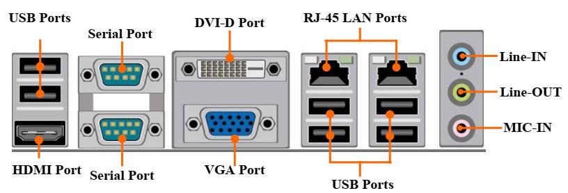
Rear I/O Back Panel Connectors
(1) High-Definition Multimedia Interface: HDMI1
This point-to-point
interface is for audio and video signals designed as a single-cable solution
for home theater and consumer electronics equipment.
(2) Serial port Connector: COM1
COM1 offers two 9-pin serial port connectors.
(3) Digital Visual Interface: DVI
This interface standard designed to maximize the visual quality of
digital display devices such as flat panel LCD computer displays and digital
projectors.
(4) D-Sub 15-pin Connector: VGA
VGA connector is the 15-pin D-subminiature female connector; it is for
the display devices, such as the CRT monitor, LCD monitor and so on.
(5) USB Port Connectors: USB ports from
USB1/UL1/ UL2
The connectors are 4-pin connector that connects USB devices to the
system board.
(6) LAN Port connectors: RJ45 LAN ports
from UL1/UL2
The connector is standard RJ45 connector for Network. It supports
10/100/1000Mbps data transfer rate.
(7) Audio Line-In, Lin-Out connector:
AUDIO1
These Connectors are 3 Phone-Jack for LINE-OUT, LINE-IN, MIC audio connections.
|
Line-in: (BLUE) |
Audio input to sound
chip |
Motherboard Internal Connectors
(1) Power Connector (24-pin block): ATXPWR
ATX
Power Supply connector: This is a new defined 24-pins connector that usually
comes with ATX case. The ATX Power Supply allows using soft power on momentary
switch that connect from the front panel switch to 2-pins Power
On jumper pole on the motherboard. When the power switch on the back of the ATX
power supply turned on, the full power will not come into the system board until
the front panel switch is momentarily pressed. Press this switch again will turn
off the power to the system board.
** recommend that you use an ATX 12V Specification 2.0-compliant power supply
unit (PSU) with a minimum of 350W power rating. This type has 24-pin and 4-pin
power plugs.
** If you intend to use a PSU with 20-pin
and 4-pin power plugs, make sure that the 20-pin power plug can provide at
least 15A on +12V and the power supply unit has a minimum power rating of 350W.
The system may become unstable or may not boot up if the power is inadequate.
** If you are using a 20-pin power plug, please refer to Figure1 for power
supply connection. Power plug form power supply and power connectors from motherboard
both adopt key design to avoid mistake installation. You can insert
the power plug into the connector with ease only in the right direction. If the
direction is wrong it is hard to fit in and if you make the connection by force
if is possible.
ATX 12V Power Connector (8-pin block) : ATX12V
This
is a new defined 8-pin connector that usually comes with ATX Power Supply. The
ATX Power Supply which fully supports AMD AM3 processor must including this
connector for support extra 12V voltage to maintain system power
consumption. Without this connector might cause system unstable because the power
supply can not provide sufficient current for system.


The BIOS is a program
located on a Flash Memory on the motherboard. This program is a bridge between
motherboard and operating system. When you start the computer, the BIOS program
will gain control. The BIOS first operates an auto-diagnostic test called POST (power
on self test) for all the necessary hardware, it detects the entire hardware
device and configures the parameters of the hardware synchronization.
Only when these tasks are completed done it gives up control of the computer to
operating system (OS). Since the BIOS is the only channel for hardware and
software to communicate, it is the key factor for system stability, and in
ensuring that your system performance as its best.
Entering Setup
Power
on the computer and by pressing <Del> immediately allows you to enter
Setup.
If the message disappears before your respond and you still wish to enter
Setup, restart the system to try again by turning it OFF then ON or pressing
the “RESET” button on the system case. You may also restart by simultaneously
pressing <Ctrl>,<Alt> and <Delete> keys. If you do not press
the keys at the correct time and the system does not boot, an error message
will be displayed and you will again be asked to Press < Del > to enter Setup
BIOS Menu Screen
The
following diagram show a general BIOS menu screen:

Function Key
In
the above BIOS Setup main menu of, you can see several options. We will explain
these options step by step in the following pages of this chapter, but let us
first see a short description of the function keys you may use here:
z Press ←→ (left, right) to select screen;
z Press ↑↓ (up, down) to choose, in the main menu, the option you want to
confirm or to modify.
z Press <Enter> to select.
z Press <+>/<–> keys when you want to modify the BIOS parameters
for the active option.
z [F1]: General help.
z [F2]: Previous value.
z [F3]: Optimized defaults.
z [F4]: Save & Reset.
z Press <Esc> to quit the BIOS Setup.
3-4 Getting Help
Main Menu
The
on-line description of the highlighted setup function is displayed at the top
right corner the screen.
Status Page Setup Menu/Option Page Setup Menu
Press F1 to pop up a
small help window that describes the appropriate keys to use and the possible
selections for the highlighted item. To exit the Help Window, press <Esc>.
Menu Bar
There are six menu bars on top of BIOS screen:
|
Main |
To change system basic
configuration |
|
Advanced |
To change system
advanced configuration |
|
Chipset |
To change chipset
configuration |
|
Boot |
To change boot
settings |
|
Security |
Password settings |
User
can press the right or left arrow key on the keyboard to switch from menu bar.
The selected one is highlighted.
Main Menu
Main menu screen
includes some basic system information. Highlight the item and then use the
<+> or <-> and numerical keyboard keys to select the value you want
in each item.

System Date
Set
the date. Please use [Tab] key
to switch between data elements.
System Time
Set
the time. Please use [Tab] key
to switch between time elements.
Advanced Menu

Launch OpROM Support:
Launch External PXE OpROM/Launch LAN1 PXE
OpROM/Launch LAN2 PXE OpROM
Use
this item to enable or disable boot option for legacy network devices.
Launch Storage OpROM
Use
this item to enable or disable boot option for legacy mass storage devices with
option ROM.
ERP Function
Use this item to enable or disable ERP function for this board. This
item should be set as [Disabled] if you wish to have Active All Wakeup
Function. PCI Subsystem Settings
Press [Enter] to enter and make settings for PCI Express Settings and PCI
Express GEN2 Settings.
PCI Express Settings
Press [Enter] to make settings for the following PCI Express Device Register Settings:
PCI Express
Device Register Settings:
Relaxed Ordering
Use
this item to enable or disable PCI express device relaxed ordering.
Extended Tag
If set as [Enabled] it will allow device to use 8-bit tag field as a
requester.
No
Snoop
Use
this item to enable or disable PCI Express device No Snoop option.
Maximum Payload
Use this item to set maximum payload of PCI Express device or allow
system BIOS to select the value.
Maximum Read Request
Use this item to set maximum read request size of PCI Express device or
allow system BIOS to select the value.
PCI Express
Link Register Settings:
ASPM Support
The optional settings: [Disabled]; [Auto]; [Force L0].
Extended Synch
If set as [Enabled] it will allow generation of extended synchronization
patterns.
Link Training Retry
Use this item to define number of retry attempts software will take to
restrain the link if previous training attempt was unsuccessful.
Link Training Timeout(uS)
Use this item to define number of microseconds software will wait before
polling ‘Link Training’ bit in link status register.
Unpopulated Links
The optional settings are: [Keep Link ON]; [Disable Link].
PCI Express GEN2 Settings
Press [Enter] to make settings for the following PCI Express GEN Devices Settings:
PCI Express GEN2 Device Register
Settings:
Completion Timeout
The optional settings are: [Default]; [Shorter];[Longer]; [Disabled].
ARI Forwarding
The optional settings are: [Disabled]; [Enabled].
AtomicOp Register Enable
The optional settings are: [Disabled]; [Enabled].
AtomicOp Egress Blocking
The optional settings are: [Disabled]; [Enabled].
ID0 Request Enable
The optional settings are: [Disabled]; [Enabled].
ID0 Completion Enable
The optional settings are: [Disabled]; [Enabled].
LTR
Mechanism Enable
The
optional settings are: [Disabled]; [Enabled].
End-End TLP Prefix Blocking
The optional settings are: [Disabled]; [Enabled].
PCI Express
GEN2 Link Register Settings
Target Link Speed
The optional settings are: [Auto]; [Force to 2.5GT/s].
Selectable De-emphasis
The optional settings are: [-3.5 dB]; [-6.0dB].
Clock Power Management
The optional settings are: [Disabled]; [Enabled].
Compliance SOS
The optional settings are: [Disabled]; [Enabled].
Hardware Autonomous Width
The optional settings are: [Disabled]; [Enabled].
Hardware Autonomous Speed
The optional settings are: [Disabled]; [Enabled].
► ACPI Settings
ACPI Sleep State
Use this item to select the highest ACPI sleep state the system will
enter when the suspend button is pressed.
The optional settings are: [S1(CPU Stop Clock)]; [S3(Suspend to RAM)].
► Wakeup Function Settings
Wake System with Fixed Time
Use this item to enable or disable system wake on alarm event. When set
as [Enabled], system will wake on the hour/min/sec specified.
CIR Wakeup
Use this item to enable or disable CIR wakeup.
PS2 KB/MS Wakeup
Use this item to enable or disable PS2 KB/MS wakeup function.
PCI PME Wakeup
Use this item to enable or disable S3/S4/S5 PCI PME wakeup function.
USB S3/S4 Wakeup
Use this item to enable or disable USB S3/S4 wakeup function.
► Trusted Computing
Press [Enter] to set TPM Configuration
TPM Support
The optional settings are: [Disabled]; [Enabled].Use this item to enable
or disable.
TPM support. O.S will not
show TPM. Reset of platform is required. When set as [Enabled], user can
further enable or disable TPM State.
► CPU Configuration
► Socket 0 CPU Information
Press [Enter] to view detailed CPU information.
Active Processor Cores
Use this item to select number of cores to enable in each processor
package.
Limit CPUID Maximum
This item should be set as [Disabled] for Windows XP.
Execute Disable Bit
The optional settings are: [Disabled]; [Enabled].
Hardware Prefetcher
Use this item to turn on/off the Mid Level Cache (L2) streamer
prefetcher.
Adjacent Cache Line Prefetch
Use this item to turn on/off prefetching of adjacent cache lines.
Intel Virtualization Technology
The optional settings: [Enabled]; [Disabled].
When set as [Enabled], a VHM can utilize the additional hardware capabilities provided
by Vanderpool Technology.
Power Technology
Use this item to enable power management features.
The optional settings are: [Disabled]; [Energy Efficient]; [Custom].
► SATA Configuration
SATA Mode
The optional settings are: [Disabled]; [IDE Mode]; [AHCI Mode].
Serial-ATA Controller 0
The optional settings are: [Disabled]; [Enhanced]; [Compatible].
Serial-ATA Controller 1
The optional settings are: [Disabled]; [Enhanced].
► Intel IGD SWSCI OpRegion
IGD-Boot Type
Use this item to select the video device which will be activated during
POST. This has no effect if external graphics present.
The optional settings are: [VBIOS Default]; [CRT]; [HDMI].
► USB Configuration
Legacy USB Support
The optional settings are: [Auto]; [Disabled]; [Enabled].
EHCI Hand-off
The optional settings are:
[Disabled]; [Enabled].
USB Transfer time-out
Use this item to set the time-out value for control, bulk, and interrupt
transfers.
Device reset time-out
Use this item to set USB mass storage device start unit command
time-out.
Device power-up delay
Use this item to set maximum time the device will take before it
properly reports itself to the host controller. ‘Auto’ uses default value: for
a root port it is 100 ms, for a hub port the delay is taken from hub
descriptor. The optional settings: [Auto]; [Manual].Select [Manual] you can set
value for the following sub-item: Device
Power-up delay in seconds, the delay range in from 1 to 40 seconds in
one second increments.
► Super IO Configuration
► COM1 Port Configuration
Press [Enter] to make settings for the following items:
Serial Port
Use this item to enable or disable serial port.
Change Settings
Use this item to select an optimal setting for super IO device.
► COM2 Port Configuration
Press [Enter] to make settings for the following items:
Serial Port
Use this item to enable or disable serial port.
Change Settings
Use this item to select an optimal setting for super IO device.
► Parallel Port Configuration
Press [Enter] to make settings for the following items:
Parallel Port
Use this item to enable or disable parallel port(LPT/LPE).
Change Settings
Use this item to change the printer port mode.
Device Mode
Use this item to change the printer port mode.
CIR Controller
Use this item to enable or disable CIR controller.
Case Open Detect
Use this item to detect case has already open or not, show message in
POST.
► PC Health Status
Press [Enter] to view
hardware health status.
► Second Super I/O Configuration
► COM3 Port Configuration
Press [Enter] to make settings for the following items:
Serial Port
Use this item to enable or disable serial port (COM).
Change Settings
Use this item to select an optimal setting for super IO device.
Serial Port Mode Select
The optional settings are: [RS232]; [RS422/RS485].
► COM4 Port Configuration
Press [Enter] to make settings for the following items:
Serial Port
Use this item to enable or disable serial port (COM).
Change Settings
Use this item to select an optimal setting for super IO device.
► COM5 Port Configuration
Press [Enter] to make settings for the following items:
Serial Port
Use this item to enable or disable serial port (COM).
Change Settings
Use this item to select an optimal setting for super IO device.
► COM6 Port Configuration
Press [Enter] to make settings for the following items:
Serial Port
Use this item to enable or disable serial port (COM).
Change Settings
Use this item to select an optimal setting for super IO device.
► Third Super I/O Configuration
► COM7 Port Configuration
Press [Enter] to make
settings for the following items:
Serial Port
Use this item to enable or disable serial port (COM).
Change Settings
Use this item to select an optimal setting for super IO device.
Serial Port Mode Select
The optional settings are: [RS232]; [RS422/RS485].
► COM8 Port Configuration
Press [Enter] to make settings for the following items:
Serial Port
Use
this item to enable or disable serial port (COM).
Change Settings
Use this item to select an optimal setting for super IO device.
► COM9 Port Configuration
Press [Enter] to make settings for the following items:
Serial Port
Use this item to enable or disable serial port (COM).
Change Settings
Use this item to select an optimal setting for super IO device.
► COM10 Port Configuration
Press [Enter] to make settings for the following items:
Serial Port
Use this item to enable or disable serial port (COM).
Change Settings
Use this item to select an optimal setting for super IO device.
► Voltage Configuration
DIMM Voltage
The optional settings are: [1.50V]; [1.65V]; [1.80V]; [1.95V].
► WatchDog Configuration
WatchDog Timer Control
Use this item to enable or disable WatchDog Timer Control. When set as
Enabled,
the following sub-items shall appear:
WatchDog Timer Value
User can set a value in the range of 4 to 255.
WatchDog Timer Unit
The optional settings are: [Second];[Minute].
► Shutdown Temperature Configuration
Use this item to select system shutdown temperature.
► SmartFan Configuration
SYSTEM FAN2 3/4 Pin Fan Select
The optional settings are: [3 Pin]; [4 Pin].
CPUFAN / SYSFAN1/SYSFAN2 SmartFan Mode
When set as [Enabled], the following sub-items shall appear:
CPUFAN / SYSFAN1/SYSFAN2 Full Speed
Temp
Use this item to set a degree for CPU/System fan1/ System fan2 FAN will
run at full speed when above the specific temperature set.
CPUFAN / SYSFAN1/SYSFAN2 Idle Temp
Use this item to set a degree for CPU/System fan1/
System fan2. FAN will idle speed when below this temperature.
CPUFAN / SYSFAN1/SYSFAN2 Stop Temp
Use this item to set a degree for CPU/System fan1/ System fan2. CPU FAN
will stop when below this temperature.
Chipset Menu

North Bridge
LOW MMIO Align
The
optional settings are: [64M]; [1024M].
VT-d
The optional settings are: [Enabled]; [Disabled].
Initiate Graphics Adapter
Select
which graphics controller to use as the primary boot device. The optional settings
are:[ IGD]; [PCI/IGD]; [PCI/PEG]; [PEG/IGD]; [PEG/PCI].
IGD Memory
Use this item to set IGD share memory size.
IGD Multi-Monitor
Use this item to enable or disable IGD multi-monitor by internal
graphics device.
PCI Express Port
The optional settings are: [Auto];[Enabled]; [Disabled].
PEG
Force Gen1
Use
this item to enable or disable PCI Express port Force Gen1.
Detect Mon-Compliance Device
Use this item to enable or disable Non-Compliance PCI Express device in
PEG.
►
South Bridge
SB Chipset Configuration
Onboard Lan1 Device/ Onboard Lan2 Device
Use
this item to enable or disable the PCI Express port in the chipset.
Restore AC Power Loss
Use this item to specify what state to go to when power is re-applied
after a power failure (G3 State). The optional settings are: [Power Off];
[Power On]; [Last State].
SLP_S4 Assertion Stretch Enable
The optional settings are: [Enabled]; [Disabled].
Deep Sx
The optional settings are: [Disabled]; [Enabled in S5]; [Enabled in S4
and S5].
Audio Configuration
Azalia HD Audio
The
optional settings are: [Enabled]; [Disabled].
Azalia Internal HDMI Codec
Use this item to enable or disable internal HDMI codec for Azalia.
High
Precision Event Timer Configuration
High Precision Timer
The optional settings are: [Enabled]; [Disabled].
► USB Configuration
Press [Enter] to further setting USB port configuration. User can enable
or disable specific USB port selected, or choose to enable or disable all USB
devices.
► ME subsystem
ME Subsystem
Use this item to enable or disable ME subsystem.
ME Temporary Disable
Use this item to enable or disable ME temporary disable help.
Boot Menu

Boot Configuration
Setup Prompt Timeout
Use
this item to set number of seconds to wait for setup activation key.
Bootup Numlock State
Use
this item to select keyboard numlock state. The optional settings are: [On];
[Off].
Quiet Boot
The
optional settings are: [Enabled]; [Disabled].
Gate A20 Active
The
optional settings are: [Upon Request]; [Always].
Option ROM Message
Use
this item to set display mode for option ROM. The optional settings are: [Force
BIOS]; [Keep Current].
Interrupt 19 Capture
The
optional settings are: [Enabled]; [Disabled].
Security Menu
Security menu allow users
to change administrator password and user password settings.

Save & Exit Menu

Save Changes and Reset
This
item allows user to reset the system after saving the changes.
Discard changes and Reset
This
item allows user to reset the system without saving any changes.
Restore Defaults
Use
this item to restore /Load default values for all the setup options.
Save as User Defaults
Use
this item to save the changes done so far as user defaults.
Restore User Defaults
Use
this item to restore defaults to all the setup options.
Launch EFI Shell from filesystem device
This item is used for attempts to launch EFI shell application from one
of the available file system devices.
Reset System with ME disable Mode
ME
will run into the temporary disable mode. Ignore if ME Ignition FW.


