US
model-Canadian model: HCD-SHAKE10, HCD SHAKE30
AEP Model, Thai Model: HCDSHAKEX30, HCDSHAKEX70
UK Model: HCDSHAKEX30
Russian Model, Australian Model: HCDSHAKEX10, HCDSHAKEX30
E Model: HCDSHAKEX10, HCDSHAKEX30, HCDSHAKEX70
•
HCD-SHAKE10 is the tuner, USB, CD Player, Bluetooth, NFC and amplifier section
in SHAKE-X10.
• HCD-SHAKE30 is the tuner, USB, CD Player, Bluetooth, NFC and amplifier
section in SHAKE-X30.
• HCDSHAKEX10 is the tuner, USB, DVD Player, Bluetooth, NFC and amplifier
section in SHAKE-X10D.
• HCDSHAKEX30 is the tuner, USB, DVD Player, Bluetooth, NFC and amplifier
section in SHAKE-X30D.
• HCDSHAKEX70 is the tuner, USB, DVD Player, Bluetooth, NFC and amplifier
section in SHAKE-X70D

[Be sure to keep your PC used
for service and checking of this unit always updated with the latest version of
your anti-virus software. In case a
virus affected unit was found during service, contact your Service Headquarters]
CD/DVD Mechanism Type :-
CDM90-DVBU204 M. Optical Pick-up Name
:- CMS-S76RFS7GP OR CMS-S76RFS7G1
POWER OUTPUT AND TOTAL HARMONIC
DISTORTION:
(US models only)
Shake-X30 only
With 4 ohm loads, both channels driven, from 150 Hz – 20,000 Hz;
rated 90 watts per channel minimum RMS power, with no more than 0.7% total
harmonic distortion from 250 milliwatts to rated output.
Shake-X10 only
With 4 ohm loads, both channels driven, from 150 Hz – 20,000 Hz; rated
80 watts per channel minimum RMS power, with no more than 0.7% total harmonic
distortion from 250 milliwatts to rated output.
NOTES ON CHIP COMPONENT REPLACEMENT
Never reuse a disconnected chip component.
Notice that the minus (--) side of a Tantalum capacitor may be damaged by heat.
LEAKAGE TEST
The AC leakage from any exposed metal part to earth ground and from
all exposed metal parts to any exposed metal part having a return to chassis,
must not exceed 0.5 mA (500 microamperes).
Leakage current can be measured by any one of three methods.
1. A commercial leakage tester, such as the Simpson 229 or RCA WT-540A. Follow
the manufacturers’ instructions to use these instruments.
2. A battery-operated AC milliammeter. The Data Precision 245 digital
multimeter is suitable for this job.
3. Measuring the voltage drop across a resistor by means of a VOM or
battery-operated AC voltmeter. The “limit” indication is 0.75 V, so analog
meters must have an accurate low-voltage scale. The Simpson 250 and Sanwa
SH-63Trd are examples of a passive VOM that is suitable. Nearly all battery
operated digital multimeters that have a 2V AC range are suitable.
The laser diode in the optical pick-up block may suffer
electrostatic break-down because of the potential difference generated by the charged
electrostatic load, etc. on clothing and the human body.
During repair, pay attention to electrostatic break-down and also use the
procedure in the printed matter which is included in the repair parts.
The flexible board is easily damaged and should be handled with care.
NOTES ON LASER DIODE EMISSION CHECK
The laser beam on this model is concentrated so as to be focused on the disc reflective
surface by the objective lens in the optical pickup block. Therefore, when
checking the laser diode emission, observe from more than 30 cm away from the
objective lens.
How to release the disc tray lock
The disc tray lock function for the antitheft of sample disc in
the shop is equipped. It can release the
lock function in the following procedure.
Releasing Procedure:
1. Press the POWER button to turn the power on.
2. Press the [FUNCTION] button to select the DVD/CD function.
3. Press the [ENTER] button and [VOCAL FADER] button simultaneously for three
seconds.
4. The message “UNLOCKED” is displayed on the screen display panel and the disc
tray is unlocked.
Note: When “LOCKED” is displayed
on the screen display panel, the disc tray lock is not released by turning the
power ,ON-OFF with the POWER button.
Connecting with a smartphone by one
touch (NFC)
Note: The
operation in this mode must use a NFC-compatible smartphone (Smartphones with a
built-in NFC function [OS: Android 2.3.3 or later, excluding Android 3.x]
1. Press the [POWER] button to turn the power on.
2. Download and install the app “NFC Easy Connect”.
Download the free Android app from Google Play by searching for “NFC Easy
Connect”.
3. Start the app “NFC Easy Connect” on the smartphone. Make sure that the application screen is
displayed.
4. Touch the smartphone to the N-Mark on the system until the smartphone
vibrates. Complete the connection by
following the instructions displayed on the smartphone.
5. When pairing is completed and the Bluetooth connection is established,
the Bluetooth device name appears in the display panel.
HOW TO OPEN THE TRAY WHEN POWER SWITCH TURN OFF
Note 1: After the side (L, R) panel, top panel section, fan
bracket and DC fan are removed, this work is done.
Note 2: Please prepare the thin
wire (clip etc. processed to the length of 8 cm or more).

COLD RESET
This mode is used to reset all the user settings to factory
setting.
Execute this mode when returning the unit to the customer.
Procedure:
1. Press POWER button to turn on the system.
2. Press STOP button and [ TUNING +>>|] button simultaneously for 3
seconds.
3. “COLD RESET” appears on the screen display panel. After that, “SONY DEMO”
appears on the screen display panel.
The system automatically turn ON and OFF once. Please be sure that the system
stay at demo mode finally before switch off the power supply.
DISC TRAY LOCK
When the disc tray does not open and “LOCKED” appears on the screen
display panel, disc tray lock mode has been activated by the shop front.
To release from Disc Tray Lock Mode
1. Press POWER button to turn on the system.
2. Press [FUNCTION] button repeatedly to select DVD/CD function.
3. Press [ENTER] button and [VOCAL FADER] button simultaneously and hold down
until “UNLOCKED” displayed on the screen display panel.
PANEL TEST MODE
This mode is used to check the buttons, knobs, screen display panel
and LEDs.
Procedure:
1. Press [POWER] to turn on the system.
2. Press STOP button and [ TUNING – ] button simultaneously for 3 seconds.
3. All LEDs and segments in screen display panel are lighted up.
This is the display check mode.
Press [ENTER] button repeatedly to toggle different display mode as below.
Segments on screen display panel:
All On --> 1st Group On --> 2nd Group On --> All On --> All Off
Single color LEDs:
All On --> 1st Group On --> 2nd Group On --> All On --> All Off
Multi Color LEDs: White --> Red --> Green --> Blue --> Off
4. Press [ S1 ] button, the button and knob check mode is activated.
5. In the button and knob check mode, the screen display panel displays “K 0
E0V0”.
Each time a button is pressed, “K” value increases. However, once a button has been pressed, it
is no longer taken into account. After all the buttons have been pressed,
"K" value will toggle between "OK" and "K26".
“E” value increases in the manner of 0, 1, 2, 3 ... if [MIC/GUITAR LEVEL] knob
is turned clockwise, or it decreases in the manner of 0, 9, 8, 7 ... if
[MIC/GUITAR LEVEL] knob is turned counterclockwise.
“V” value increases in the manner of 0, 1, 2, 3 ... if [VOLUME/DJ CONTROL] knob
is turned clockwise, or it decreases in the manner of 0, 9, 8, 7 ... if
[VOLUME/ DJ CONTROL] knob is turned counterclockwise.
6. To release from this mode, press the buttons in the same manner as step 2,
or disconnect the power cord.
VERSION DISPLAY MODE
This mode is used to check the software version.
Procedure:
1. Press POWER button to turn on the system.
2. Press [ S3TUNING – |<<] button and [LIGHT MODE] button simultaneously
for 3 seconds.
The SC software version and CD/DVD software appear on the screen display panel.
After that, it returns to the default display.
MODEL AND DESTINATION DISPLAY MODE
This mode is used to check the model and destination of the set.
Procedure:
1. Press POWER button to turn on the system.
2. Press STOP] button and [S3 TUNING – |<<.] button simultaneously for 3
seconds. All segments in screen display
panel are lighted up.
3. Press [ S2 + ] button. Model information appears on the screen display
panel.
4. Press [ S2 + ] button again. Destination information appears on the screen
display panel.
5. Press S2 button and [ TUNING –
|<< ] button simultaneously for 3 seconds to exit.
SHOP FRONT DEMO
The playback started automatically and the “ * DEMO * ” appears on
the screen display panel. This is the
Shop Front Demo mode which is activated by the shop front.
To release from Shop Front Demo Mode
1. Press STOP button and [SOUND FIELD] button simultaneously for 5
seconds.
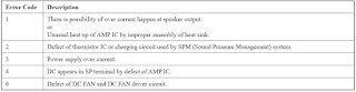
ERROR
CODES
Switching Regulator [SMPS] (SSN-172AD) DIAGNOSIS
FLOW (HCD-SHAKE10 – SHAKE30)

SWITCHING REGULATOR [SMPS] SSN-171AD DIAGNOSIS
HCDSHAKEEX70

Top panel board schematic
