How to enter the service mode of AOC D26W931, AOC D32W931, AOC LC32W053, service mode adjustments, dis-assemble procedure, repair flow chart and more
How to setting the Ca210
channel, you can reference to Ca210 user guide or simple use the “Memory CH” up
or down to set the channel to 05 channel, and use the “Mode” key to set the
mode to xyLv.
Following
is the procedure to do white-balance adjust
Press
menu key and then press number key 1 9 9 9 Enter,
it will achieve the factory mode.
In
the White Balance you can adjust 3 items.
SCALER
GAIN R, G, B Gain adjust.
Adjust AV Source
1.
Set the pattern generator to timing 307 or PAL-M timing. And Select the item of
Current Source and select composite Source
2.
Switch the Ca210 to xyLv-mode (with press “MODE” button)
3.
Switch the Ca210 channel to Channel 05 (with up or down “MEMORY CH” button)
4.
The LCD-indicator on Ca210 will show x =285, y =293, Lv can adjust to More than
350cd/cm2(at full white).
5.
Enter the item “Color Temp” to select Normal to adjust.
6.
Use the item R Gain,G Gain or B Gain to adjust white balance: use 80 IRE
(Pattern 141) signal, and adjust the white balance, until the Ca210 show x
=285, y =293.
Adjust HDMI Source
1.
Set the pattern generator to timing 347 or HDMI-720P@60Hz timing. And Select
the item of Current Source and select HDMI Source
2.
Switch the Ca210 to xyLv-mode (with press “MODE” button)
3.
Switch the Ca210 channel to Channel 05 (with up or down “MEMORY CH” button)
4.
The LCD-indicator on Ca210 will show x =285, y =293, Lv can adjust to More than
350cd/cm2(at full white).
5.
Enter the item “Color Temp” to select Normal to adjust.
6.
Use the item R Gain,G Gain or B Gain to adjust white balance: use 80 IRE
(Pattern 141) signal, and adjust the white balance, until the Ca210 show x
=285, y =293.
Adjust VGA Source
1.
Set the pattern generator to timing 137 or 1024*768@60Hz timing. And Select the
item of Current Source and select VGA Source
2.
Switch the Ca210 to xyLv-mode (with press “MODE” button)
3.
Switch the Ca210 channel to Channel 05 (with up or down “MEMORY CH” button)
4.
The LCD-indicator on Ca210 will show x =285, y =293, Lv can adjust to More than
350cd/cm2(at full white).
5.
Enter the item “Color Temp” to select Normal to adjust.
6.
Use the item R Gain,G Gain or B Gain to adjust white balance: use 80 IRE
(Pattern 141) signal, and adjust the white balance, until the Ca210 show x
=285, y =293.
Adjust Component Source
1.
Set the pattern generator to timing 314 or HDTV-720p@60Hz timing. And Select
the item of Current Source and select Component Source
2.
Switch the Ca210 to xyLv-mode (with press “MODE” button)
3.
Switch the Ca210 channel to Channel 05 (with up or down “MEMORY CH” button)
4.
The LCD-indicator on Ca210 will show x =285, y =293, Lv can adjust to More than
350cd/cm2(at full white).
5.
Enter the item “Color Temp” to select Normal to adjust.
6.
Use the item R Gain,G Gain or B Gain to adjust white balance: use 80 IRE
(Pattern 141) signal, and adjust the white balance, until the Ca210 show x
=285, y =293.
7.
Enter the item “Color Temp” to select Cool to adjust.
8.
Use the item R Gain,G Gain or B Gain to adjust white balance: use 80 IRE
(Pattern 141) signal, and adjust the white balance, until the Ca210 show x
=272, y =278.
9.
Enter the item “Color Temp” to select Warm to adjust.
10.
Use the item R Gain,G Gain or B Gain to adjust white balance: use 80 IRE
(Pattern 141) signal, and adjust the white balance, until the Ca210 show x
=313, y =329.

Analogue signal timing


HDMI signal timing

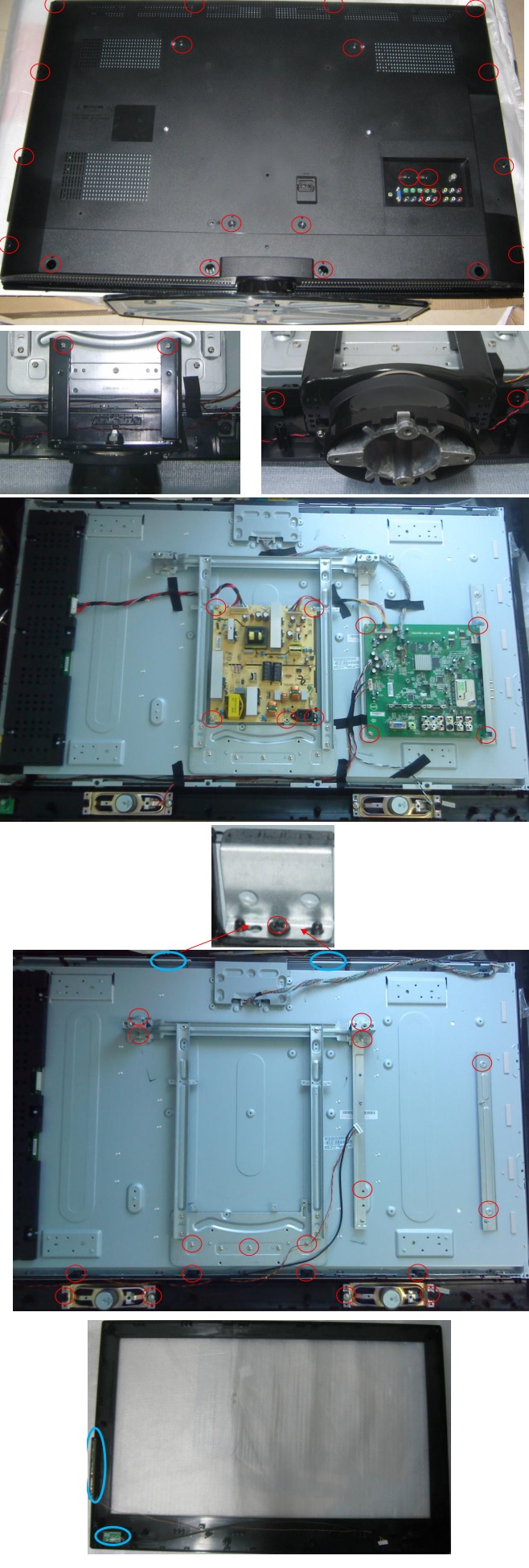
Disassembly
D26W931
Remove
the screws to remove the rear cover ass’y and stand ass’y
2.
Remove the screws to remove main board, power board, bracket and speakers and
separate panel and bezel.
3.
Remove the screws to remove IR board and key board.

D32W931
Remove
the screws to remove the rear cover ass’y and base ass’y
2.
Remove the screws to remove main board, power board and bracket.
3.
Remove the screws to remove inverter board, speakers and bracket and separate
panel and bezel.
4.
Remove the screws to remove key board and IR board'.

LC32W053
Remove
the screws to remove the rear cover.
2.
Remove the screws to remove the stand base, main board, power board, inverter
board and LVDS to FFC board.
3.
Remove the screws to remove the bracket and separate panel and bezel.
4.
Remove the screws to remove IR board, key board and speakers.

LC42H053
Remove
the screws to remove the rear cover.
Remove
the screws to remove the stand base
3.
Remove the screws to remove main board and power board.
4.
Remove the screws to remove the bracket and speakers and separate the panel and
bezel.
5.
Remove the screws to remove key board and IR board.
Repair Flow Chart


No comments:
Post a Comment