Safety regulations require
that during a repair:
Connect the unit to the mains via an isolation transformer.
Replace safety components indicated by the symbol , only by components
identical to the original ones. Any other component substitution (other than
original type) may increase risk of fire or electrical shock hazard.

Be careful during measurements in the live voltage section. The primary side of the power supply , including the heat sink, carries live mains voltage when you connect the player to the mains (even when the player is “off”!). It is possible to touch copper tracks and/or components in this unshielded primary area, when you service the player. Service personnel must take precautions to prevent touching this area or components in this area.
A “lighting stroke” and a stripe-marked printing
on the printed wiring board, indicate the primary side of the power supply.
This unit employs a laser.
Only qualified service personnel may remove the cover, or attempt to service
this device (due to possible eye injury).
Note: Never replace modules, or components, while the unit is “on”
Centre speaker:
Output power: 166 W RMS
(30% THD)
Speaker impedance: 4 ohm
Speaker drivers: 1 x 78 mm (3") full range
Dimensions (WxHxD): 223 x 100 x 80 mm
Weight: 0.65 kg
Front/Rear speaker:
Output power: 4 x 166 W RMS (30% THD)
Speaker impedance: 4 ohm
Speaker drivers: 1 x 78 mm (3") full range
Dimensions (WxHxD):
HTD5510: 90 x 185 x 82 mm (front/ rear)
Subwoofer
Output power: 166 W RMS (30% THD)
Impedance: 4 ohm
Speaker drivers: 165 mm (6.5") woofer
Dimensions (WxHxD): 178 x 300 x 343 mm
Weight: 3.66 kg
Cable length: 3.3 m
Procedure of replacing
the defective loader.
Solder the ESD
protection point.
Put a paper clip on the flex
foil to short circuit the contacts [see the fig]
Replace the defective
loader with new loader
Remove paper clip from
the flex foil and connect it to the new loader
Remove solder joint on
ESD protection point
[The laser diode of this loader is protected against ESD by a solder a point short-circuits the laser diode to ground. For proper functionality of the loader this solder joint must be removed after connecting loader to the set.

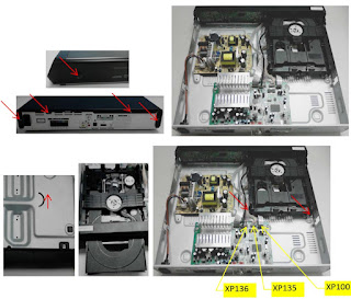
Dismantling
Open the top cover. Remove
2 screws on both sides and 4 screws on back panel, then open the cover.
Dismantle the loader. Open
the tray, dismantle the CD door, remove 2 screws beside the loader. disconnect
connectors(XP100,XP135,XP136),then pull up the loader.
Dismantle the main board.
Disconnect connectors(XP221,XP82,XS751),remove 2 screws on the board and 6
screws on back panel.
Dismantle the power board.
Remove 4 screws on the board.

Dismantle the front panel
and the front control board. Loosen the 2 buckles on both sides and 2 buckles under
bottom cover, then remove 5 screws on the front control board.

Software Upgrade
There are 2 ways to
software upgrade:
First:
Upgrade from USB:
Copy the upgrade file HTD5510_X X.BIN to USB then press the USB key on RC or
SOURCE key on front panel.
When upgrade file detected, select "Yes" to upgrade, select
"Cancel" to cancel.
After upgrading begins, a message “DO NOT POWER OFF” will show, or the product
will hang up and upgrading failed.
Second:
Upgrade from Disc:
Copy the upgrade file HTD5510_X X.BIN to disc then read the disc.
When upgrade file detected, select "Yes" to upgrade, select “Cancel “to
cancel.
After upgrading begins, a message “DO NOT POWER OFF” will show, or the product
will hang up and upgrading failed.
2. Check the version information after upgraded.
Press the setup key on RC , select Preference Setup, and then Version info ,
press OK Key you will see a interface below:

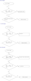
Troubleshooting chart


Power board schematic


Amplifier board circuit
diagram

CONNECTOR PIN VOLTAGES

No comments:
Post a Comment