Saturday, August 02, 2014
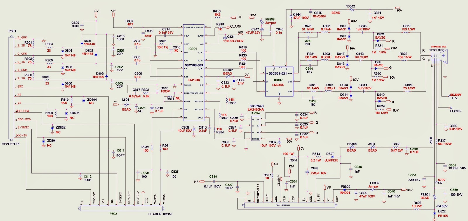
VIEWSONIC G90fB-4 Model No. VS10794 - 19” Digital Controlled Color Monitor - Schematic Full
Professional technician for all kind of electronic equipment. Doing since 1974.
VIEWSONIC - VS10859 MONITOR - FLICKER ADJUSTMENT - Spare part list
Model - VS10859
Product name: VA2012wb-1-W _ VA2012w/wb-2-W _ VX2025wm-W
LED flicker appeared when change the power saving mode to
normal picture in ORT test. In order to solve the abnormal phenomenon, power BD
modified.
* Before change:
Power board P/N: AS08B532009
Description: PWR MODULE (DTA) EADP-64CF B,90~264V GP. [Rev:
A]
* After change:
Power board P/N: AS08B532009
Description: PWR MODULE (DTA) EADP-64CF B, 90~264V GP. [Rev:
B]
* Before change:
Power board P/N: AS08B532009, Description: PWR
MODULE (DTA) EADP-64CF B, 90~264V GP Rev: Transformer P/N:MV-CE 5048A
,circuitry qty:4,Diode ZD1:7.5A.
* After change:
Power board P/N: AS08B532009, Description: PWR
MODULE (DTA) EADP-64CF B,90~264V GP Rev: B Transformer P/N:MV-CE 5048B
circuitry qty:5,Diode ZD1:12A.
Click on the pictures to Magnify
Spare Part List
Item
|
Description
|
Ref. P/N
|
Location
|
|
1
|
Accessories:
|
Power cable
|
DM333181801
|
Power cable
|
2
|
Audio cable
|
DDW9ZAPA009
|
Audio cable
|
|
3
|
VGA cable
|
DDL7VDPC005
|
VGA cable
|
|
4
|
Board Assembly:
|
Power board
|
AS08B532009
|
Power board
|
5
|
main board
QDI 21W0VAMB002
|
1SW0VAMB009
|
Main board for QDI
|
|
6
|
main board
AUO 21W0VAMB002
|
1SW0VAMB025
|
Main board for AUO
|
|
7
|
Button board 23W0VABB009
|
1SW0VABB003
|
Button board
|
|
8
|
Inverter board
|
AS023360D18
|
Inverter board
|
|
9
|
Cabinets:
|
Front bezel assy black
|
34W0VALB000
|
front bezel ass'y
|
10
|
back cover assy black
|
25W0VALC007
|
back cover assy
|
|
11
|
Cables:
|
Cable MB-LCD
|
DD0L9VLC023
|
Cable MB-LCD
|
12
|
Cable MB-BB
|
DDW0VABU007
|
Cable MB-BB
|
|
13
|
Cable MB-INV
|
DD0W0EIV008
|
Cable MB-INV
|
|
14
|
Documentation:
|
User manual + CD wizard
|
HGW0VA01013
|
User manual
|
15
|
Electronic
Components: |
20" QD20AL01 REV.01 GP
|
AA20AL01004
|
QDI LCD panel
|
16
|
20" QD20AL01
REV.01 A- GP
|
AA20AL01012
|
QDI LCD panel 2nd source
|
|
17
|
20"AUO M201EW01 V.0 GP
|
AAM201EW007
|
AUO LCD panel
|
|
18
|
LCD 20" M201EW01
V.0 GP
|
AAM201EW058
|
AUO LCD panel 2nd source
|
|
19
|
Speaker assy
|
DN0TE130F01
|
speaker assy
|
|
20
|
Miscellaneous:
|
Screw
|
MF30040IJB3
|
SCREW F 3.0*4.0-I(MC) GP
|
21
|
Screw
|
MF30060BBJ6
|
SCREW M3.0*6, B(NI) GP
|
|
22
|
LCD film
|
JXW0ZB01019
|
LCD FILM
|
|
23
|
Screw
|
MF40140IJ29
|
SCREW F4.0*14-I(BNI) GP
|
|
25
|
RUBBER PLUG VESA
|
GAL9V002014
|
RUBBER PLUG VESA
|
|
HINGE COVER
|
EBW0VA03020
|
HINGE COVER W0VA
|
||
27
|
Packing Material:
|
EPE bags
|
HAL0T002019
|
EPE bags
|
28
|
Carton
|
HFW0VA03015
|
carton
|
|
29
|
End cap (L)
|
HBW0VA01019
|
cushion
|
|
30
|
End cap (R)
|
HBW0VA02015
|
cushion
|
|
31
|
Plastics:
|
Stand assy
|
26W0VASA016
|
Stand ASSY
|
base assy
|
38W0VABS010
|
base assy
|
||
Professional technician for all kind of electronic equipment. Doing since 1974.
Friday, August 01, 2014
AIWA CSD-EX110 – SCHEMATIC (Circuit Diagram)
Professional technician for all kind of electronic equipment. Doing since 1974.
SONY KLV-26S550 - KLV-32S530 - KLV-37S550 - Factory reset AND Hotel Mode Asjustments
Sony KLV-26S550A-KLV-32S530A_KLV-32S550A_KLV-32S550A/L_KLV-32S550A/T_KLV-37S550A
[Factory reset – Hotel Mode]
Preset "Test" button on remote commander.
* Press the following buttons simultaneously on the remote
commander RM-GA016 for a few seconds.
* Once completed, the below button operates as a TEST button.
Resetting the User Menu- Factory Reset
* While TV on standby mode, press the following sequence on
the Remote commander.
* Select SERVICE with 2 or 5 On the Remote Commander.
* Select AUTO SET FACTORY with 1 or 4 On the Remote Commander.
* Select data value with 3 or 6 On the Remote Commander to 0 to
current condition. Refer to
Service Items Table.
* Press <POWER> to exit.
SERVICE ITEMS
[Board & Panel Replacement: When replacing the BT board
and Panel readjust the W/B.]
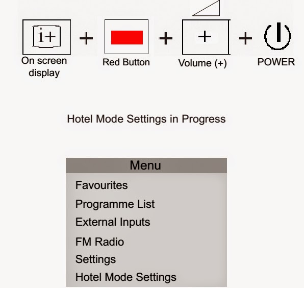
Hotel Menu Mode. {KLV-26, 32, 37 S550A - RM-GA016}
* While TV set is on standby, press the following sequence on
the remote commander (RM-GA016).
* When the TV turns on, the indication "Hotel Mode Settings
in Progress" appears on the bottom center of the screen.
* Press 'Menu' on the remote commander.
* Press UP / DN to select 'Hotel Mode Settings' and press (+).
The following menu appears on the screen.
* Press Right / Left to
select 'Hotel Mode'. Then press (+).
* Now press Left / Right then Up / Dn to select 'ON' and press (+). [The TV set resets and restarts.]
* Now press 'Menu' on the remote commander.
The following menu confirms the hotel mode is ON. (see all
the screen display)
Exiting Hotel Menu Mode.
* While TV set is ON, press the following sequence on the remote
commander (RM-GA016).
* The TV set restarts and show "Hotel Mode Settings in Progress"
on the bottom center of the screen.
* Now press 'Menu' on the remote commander.
* The following menu confirms the hotel mode is OFF.
Professional technician for all kind of electronic equipment. Doing since 1974.
SONY KLV-32S550A - KLV-26S550A – HOW TO DISASSEMBLE – LED BLINKING CODES
SONY KLV-32S550A - KLV-26S550A –DISASSEMBLE – LED BLINKING
CODES
KLV-32S550A (RM-GA016) – [GE, ME, Philippines, (Blue) Russia, South Africa]
KLV-32S550A/T (RM-GA016) [GE, ME, Philippines, (Brown) Russia, South Africa]
KLV-37S550A (RM-GA016) [GE, India, Iran, ME, Philippines,
Russia, Thailand, Tunisia]
LED BLINKING CODES – SELF DIAGNOSIS FUNTION – REMOVAL OF
BACK COVER & SCREW SIZES.
Blinking codes: Triangle chart
KLV-26S550A, 32S530A, 32S550A, 32S550A/L, 32S550A/T
KLV-37S550A
R2 Board and Rear Cover Removal. [KLV-26S550A/1, 26S550A/3]
R2 and Rear Cover Removal [KLV-32S550A/1, 32S550A/3]
Removal of Rear Cover Procedure
Removal of Switch Unit
Push and slant towards inner side of set to remove Switch
Unit correctly.
Professional technician for all kind of electronic equipment. Doing since 1974.
Subscribe to:
Posts (Atom)