There
exists HIGH VOLTAGE ELECTRICITY with high current capabilities in the circuits
of the HIGH VOLTAGE TRANSFORMER secondary and filament terminals. It is extremely
dangerous to work on or near these circuits with the oven energized.
DO NOT measure the voltage in the high voltage circuit including filament
voltage of magnetron.
Never
touch any circuit wiring with your hand nor with an insulated tool during
operation.
Servicemen
should remove their watches whenever working close to or replacing the magnetron.

Using +20sec Pad
This is a ONE TOUCH COOK pad.
By touching the +20sec pad once, you can start heating instantly.
You can increase the cooking time by pressing the +20sec pad while heating is being done.
A cooking time increases by 20 seconds at each press on +20sec pad. But it can not exceed the maximum time. Like traditional cooking, you may find that, depending on the food’s characteristics or your tastes, you
have to adjust the cooking times slightly. Before operating the oven, times can be increased/decreased using either the time pads or +20sec button.
During the operating, time may only be added by using the +20sec button.
Memory
Pads ProgrammingBy touching the +20sec pad once, you can start heating instantly.
You can increase the cooking time by pressing the +20sec pad while heating is being done.
A cooking time increases by 20 seconds at each press on +20sec pad. But it can not exceed the maximum time. Like traditional cooking, you may find that, depending on the food’s characteristics or your tastes, you
have to adjust the cooking times slightly. Before operating the oven, times can be increased/decreased using either the time pads or +20sec button.
During the operating, time may only be added by using the +20sec button.
1. Hold down PROGRAM LOCK pad and then press PROGRAM pad. Hold together for 2
sec.
Be sure to press the pads firmly.
Result: PROG indicator appears in the digital display.
Be sure to press the pads firmly.
Result: PROG indicator appears in the digital display.
2.
Press appropriate NUMBER pad for the desired memory number.
Result: Selected memory program code appears below the PROGRAM indicator.
Result: Selected memory program code appears below the PROGRAM indicator.
3.
Select power level by pressing the POWER LEVEL pad.
Result: Default power level HIGH appears in the display at first press of the POWER LEVEL pad.
Press the POWER LEVEL pad one or more times until you get the desired power level.
Result: Default power level HIGH appears in the display at first press of the POWER LEVEL pad.
Press the POWER LEVEL pad one or more times until you get the desired power level.
4.
Press NUMBER pads to set the cooking time.
Result: The maximum time according to each cooking power level can be referred to in the title “Power Levels and Time Variations”. The NUMBER pads will not operate or respond when you press a cooking time exceeding the maximum value.
Result: The maximum time according to each cooking power level can be referred to in the title “Power Levels and Time Variations”. The NUMBER pads will not operate or respond when you press a cooking time exceeding the maximum value.
NOTE:
It is not possible to set a cooking time for longer than the maximum time
allowed on the chosen program. The power level indicator will flash and it is
advisable to press CANCEL and to enter a new power level and cooking time.
5.
Hold down PROGRAM LOCK pad and then press PROGRAM pad. Hold together for 2 sec
once again.
Result: PROG indicator and memory number indicator blink 3 times in the digital display with a beep sound. And then the display goes blank.
Caution: Be sure to press the pads firmly in the right position.
Result: PROG indicator and memory number indicator blink 3 times in the digital display with a beep sound. And then the display goes blank.
Caution: Be sure to press the pads firmly in the right position.
6.
When you want to program more, repeat the procedures above again.
Memory programs are available up to 30 items. Make sure the unit is properly programmed.
After programming is finished, all you have to do for memory cooking is to press the NUMBER pad. Then the selected memory program automatically starts cooking.
How
to Operate Memory CookingMemory programs are available up to 30 items. Make sure the unit is properly programmed.
After programming is finished, all you have to do for memory cooking is to press the NUMBER pad. Then the selected memory program automatically starts cooking.
After
having finished memory programming, just press the NUMBER pad of the memory
number you want to select. The oven will automatically start heating according
to the pre-programmed cooking time and power
level after a short delay (5 sec).
level after a short delay (5 sec).
1.Make
sure the oven is plugged into a properly earthed electrical outlet and ‘ON’
appears in the display window.
2.
Open the door.
The oven lamp will be turned on.
The oven lamp will be turned on.
3.
Put the food into a suitable container, place it in the centre of the oven and
then close the door securely.
Result: The oven lamp will go off.
Result: The oven lamp will go off.
4.
Press NUMBER pad.
Result: After 2 seconds, the selected memory program automatically starts heating.
Result: After 2 seconds, the selected memory program automatically starts heating.
Stopping
the Cooking
You
can stop cooking at any time so that you can:
• Check the food
• Turn the food over or stir it
• Leave it to stand
To stop the cooking;
• Turn the food over or stir it
• Leave it to stand
To stop the cooking;
Temporarily:
Open the door or press DN pad once.
Result: Cooking stops. To resume cooking, close the door and press again.
* Completely: Press the DN pad twice.
Result: The cooking settings are cancelled.
If you want to cancel any cooking settings before starting cooking, simply press CANCEL pad once.
Result: Cooking stops. To resume cooking, close the door and press again.
* Completely: Press the DN pad twice.
Result: The cooking settings are cancelled.
If you want to cancel any cooking settings before starting cooking, simply press CANCEL pad once.
Magnetron
and Hi voltage transformer Replacement
Remove
the magnetron including the shield case, permanent magnet, choke coils and
capacitors (all of which are contained in one assembly).
1.
Remove the outer panel.
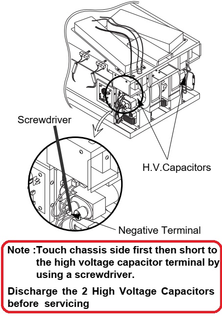
NOTE: Before servicing, make sure to discharge electric charge remaining on the high voltage capacitors or wait for more than 5 min.
2. Remove the back cover.
3. Disconnect all lead wires from the magnetron.
4. Remove screws securing the duct-MGT and duct-fan.
5. Remove the nut-flanges securing the magnetron by using a box wrench
NOTE: Before servicing, make sure to discharge electric charge remaining on the high voltage capacitors or wait for more than 5 min.
2. Remove the back cover.
3. Disconnect all lead wires from the magnetron.
4. Remove screws securing the duct-MGT and duct-fan.
5. Remove the nut-flanges securing the magnetron by using a box wrench
6.
Take out the magnetron very carefully.
NOTE1: When removing the magnetron, make sure that its antenna does not hit any adjacent parts, or it may be damaged.
NOTE2: When replacing the magnetron, be sure to remount the magnetron gasket in the correct position and make sure the gasket is in good condition.
NOTE1: When removing the magnetron, make sure that its antenna does not hit any adjacent parts, or it may be damaged.
NOTE2: When replacing the magnetron, be sure to remount the magnetron gasket in the correct position and make sure the gasket is in good condition.

1.Discharge
the high voltage capacitor.
2. Disconnect all the leads.
3. Remove the mounting bolts securing the HVT.
4. Reconnect the leads correctly and firmly.
2. Disconnect all the leads.
3. Remove the mounting bolts securing the HVT.
4. Reconnect the leads correctly and firmly.
Door
Assembly and door handle Replacement
Be
sure to wear gloves when you disassemble or assemble the parts.
1. Remove hex bolts securing the upper hinge and lower hinge. Then remove the door assembly.
2. Insert the flat screwdriver or thin metal plate into the gap between the door E and door C to remove Door C from the door assembly.
3. Remove 2 screws securing the Door Handle.
4. Unbend the 6 metal tabs around the trim of Decoration Door Cover.
5. Remove 3 screws securing the Door E Ass’y.
6. Remove upper hinge and lower hinge.
7. Remove Decoration Door, Screen B, Key-Door, Spring-Key, Pin-Key as needed.
1. Remove hex bolts securing the upper hinge and lower hinge. Then remove the door assembly.
2. Insert the flat screwdriver or thin metal plate into the gap between the door E and door C to remove Door C from the door assembly.
3. Remove 2 screws securing the Door Handle.
4. Unbend the 6 metal tabs around the trim of Decoration Door Cover.
5. Remove 3 screws securing the Door E Ass’y.
6. Remove upper hinge and lower hinge.
7. Remove Decoration Door, Screen B, Key-Door, Spring-Key, Pin-Key as needed.
Removal
of Door Handle

1.Remove
hex bolts securing the upper hinge and lower hinge. Then remove the door assembly.
2. Insert the flat screwdriver or thin metal plate into the gap between the door E and door C to remove Door C from the door assembly.
NOTE: Be careful when handling Door C as is fragile.
NOTE: The thickness of the flat screwdriver or thin metal plate inserted into the gap should be 0.5mm or less.
3. Remove 2 screws securing the Door Handle to the Door E Ass’y.
4. Unbend the 2 metal tabs at both ends of the Door Handle to remove the Door Handle Cover from the Door Handle.
2. Insert the flat screwdriver or thin metal plate into the gap between the door E and door C to remove Door C from the door assembly.
NOTE: Be careful when handling Door C as is fragile.
NOTE: The thickness of the flat screwdriver or thin metal plate inserted into the gap should be 0.5mm or less.
3. Remove 2 screws securing the Door Handle to the Door E Ass’y.
4. Unbend the 2 metal tabs at both ends of the Door Handle to remove the Door Handle Cover from the Door Handle.
[After
replacement of the defective component parts of the door, reassemble it and
follow the instructions below for proper installation and adjustment so as to
prevent an excessive microwave leakage]
1.
When mounting the door to the oven, be sure to adjust the door parallel to the
bottom line of the oven face plate by moving the upper hinge and lower hinge in
the direction necessary for proper alignment.
2. Adjust so that the door has no play between the inner door surface and oven front surface. If the door assembly is not mounted properly, microwave energy may leak from the space between the door and oven.
3. Do the microwave leakage test.
2. Adjust so that the door has no play between the inner door surface and oven front surface. If the door assembly is not mounted properly, microwave energy may leak from the space between the door and oven.
3. Do the microwave leakage test.
Procedure
for Measurement of Microwave Energy Leakage
1)Pour
275 ±15cc of 20°C±5°C ( 68°F±9°F ) water in a beaker which is graduated to
600cc, and place the beaker in the center of the oven.
2) Start to operate the oven and measure the leakage by using a microwave energy survey meter.
3) Set survey meter with dual ranges to 2,450MHz.
4) When measuring the leakage, always use the 2 inch spacer cone with the probe. Hold the probe perpendicular to the cabinet door. Place the spacer cone of the probe on the door and/or cabinet door seam and move along the seam, the door viewing window and the exhaust openings moving the probe in a clockwise direction at a rate of 1 inch/sec. If the leakage testing of the cabinet door seam is taken near a corner of the door, keep the probe perpendicular to the areas making sure that the probe end at the base of the cone does not get closer than 2 inches to any metal. If it gets closer than 2 inches, erroneous readings may result.
5) Measured leakage must be less than 4mW/cm2, after repair or adjustment.
2) Start to operate the oven and measure the leakage by using a microwave energy survey meter.
3) Set survey meter with dual ranges to 2,450MHz.
4) When measuring the leakage, always use the 2 inch spacer cone with the probe. Hold the probe perpendicular to the cabinet door. Place the spacer cone of the probe on the door and/or cabinet door seam and move along the seam, the door viewing window and the exhaust openings moving the probe in a clockwise direction at a rate of 1 inch/sec. If the leakage testing of the cabinet door seam is taken near a corner of the door, keep the probe perpendicular to the areas making sure that the probe end at the base of the cone does not get closer than 2 inches to any metal. If it gets closer than 2 inches, erroneous readings may result.
5) Measured leakage must be less than 4mW/cm2, after repair or adjustment.
Note
on Measurement
1) Do not exceed the limited scale.
2) The test probe must be held on the grip of the handle, otherwise a false reading may result when the operator's hand is between the handle and the probe.
3) When high leakage is suspected, do not move the probe horizontally along the oven surface; this may cause damage to the probe.
4) Follow the recommendation of the manufacturer of the microwave energy survey meter.
Record
keeping and notification after measurement1) Do not exceed the limited scale.
2) The test probe must be held on the grip of the handle, otherwise a false reading may result when the operator's hand is between the handle and the probe.
3) When high leakage is suspected, do not move the probe horizontally along the oven surface; this may cause damage to the probe.
4) Follow the recommendation of the manufacturer of the microwave energy survey meter.
1) After adjustment and repair of a radiation preventing device, make a repair
record for the measured values, and keep the data.
2) If the radiation leakage is more than 4mW/cm2 after determining that all parts are in good condition, functioning properly and the identical parts are replaced as listed in this manual, notify that fact to ; CENTRAL SERVICE CENTRE
3) At least once a year have the microwave energy survey meter checked for accuracy by its manufacturer.
2) If the radiation leakage is more than 4mW/cm2 after determining that all parts are in good condition, functioning properly and the identical parts are replaced as listed in this manual, notify that fact to ; CENTRAL SERVICE CENTRE
3) At least once a year have the microwave energy survey meter checked for accuracy by its manufacturer.

Replacement
of Fuse, H.V.Fuse, Drive Motor & Ass’y Stirrer
1.Disconnect
the oven from the power source.
2. Remove defective fuse from Noise filter.
3. When replacing the fuse, be sure to use an exact replacement part. If new fuse blows out again after replacement, check the primary interlock switch, door sensing switch and interlock monitor switch.
4. When the above three switches operate properly, check if any other part such as the control circuit board, ventilation motor or high voltage transformer is defective.
2. Remove defective fuse from Noise filter.
3. When replacing the fuse, be sure to use an exact replacement part. If new fuse blows out again after replacement, check the primary interlock switch, door sensing switch and interlock monitor switch.
4. When the above three switches operate properly, check if any other part such as the control circuit board, ventilation motor or high voltage transformer is defective.
Replacement
of Drive Motor
1. Remove outer panel and back-cover.
2. Disconnect all the lead wires from the drive motor.
3. Remove a screw securing the drive motor.
4. When replacing the drive motor, be sure to remount it in the correct position with the coupler.
5. Connect all the leads to the drive motor.
6. Screw the drive motor to the bracket motor with a screw driver.
1. Remove outer panel and back-cover.
2. Disconnect all the lead wires from the drive motor.
3. Remove a screw securing the drive motor.
4. When replacing the drive motor, be sure to remount it in the correct position with the coupler.
5. Connect all the leads to the drive motor.
6. Screw the drive motor to the bracket motor with a screw driver.

Replacement
of Ass’y Stirrer
1.Remove
a screw securing the drive motor.
2. Open the door.
3. Hold side stoppers of ceiling cover (Ass’y Stirrer Cover) with both hands and pull them in and down.
4. Take the ceiling cover out of the oven cavity.
5. Remove plastic clips securing the Ass’y Stirrer.
Caution: When removing the Ass’y Stirrer Cover, be sure to be extremely careful about the exposed inside components on the top of the oven cavity. If any of them are deformed, abnormal symptom can happen such as arcing or sparks during operation.
2. Open the door.
3. Hold side stoppers of ceiling cover (Ass’y Stirrer Cover) with both hands and pull them in and down.
4. Take the ceiling cover out of the oven cavity.
5. Remove plastic clips securing the Ass’y Stirrer.
Caution: When removing the Ass’y Stirrer Cover, be sure to be extremely careful about the exposed inside components on the top of the oven cavity. If any of them are deformed, abnormal symptom can happen such as arcing or sparks during operation.

Replacement
of Lamp
You
don’t need to remove the outer panel or other parts in order to replace a lamp.
1. Remove a screw securing the lamp cover.
2. Remove the lamp by rotating it clockwise.
3. Replace with a new lamp by rotating it counterclockwise.
NOTE : If it is necessary to replace the lamp holder, you can disconnect lead wires by pushing down on the hole of lead wires using a long pointed tool.
1. Remove a screw securing the lamp cover.
2. Remove the lamp by rotating it clockwise.
3. Replace with a new lamp by rotating it counterclockwise.
NOTE : If it is necessary to replace the lamp holder, you can disconnect lead wires by pushing down on the hole of lead wires using a long pointed tool.
Replacement
of Air Filter
Pull
out the spacer pins at both ends of the Air Filter. Then the locking clamps
inside are released.
2. Lift the Air Filter off the post carefully.
Note: Spacer pins are not detachable from the Air Filter.
2. Lift the Air Filter off the post carefully.
Note: Spacer pins are not detachable from the Air Filter.
High
Voltage Capacitor Replacement
It
is not necessary to remove Magnetron in order to remove HVC.
1. Remove the outer panel and back cover.
2. Discharge the high voltage capacitor.
3. Remove HVT wire and H.V.Fuse.
4. Remove screws securing HVC bracket.
1. Remove the outer panel and back cover.
2. Discharge the high voltage capacitor.
3. Remove HVT wire and H.V.Fuse.
4. Remove screws securing HVC bracket.
Magnetron
Continuity
checks can indicate only an open filament or a short magnetron. To diagnose an open
filament or short magnetron :
1. Isolate the magnetron from the circuit by disconnecting its leads.
2. A continuity check across the magnetron filament terminals should indicate one ohm or less.
3. A continuity check between each filament terminal and magnetron case should read open.
1. Isolate the magnetron from the circuit by disconnecting its leads.
2. A continuity check across the magnetron filament terminals should indicate one ohm or less.
3. A continuity check between each filament terminal and magnetron case should read open.

High
Voltage Capacitor
1.Check
continuity of the capacitor with the meter set at the highest resistance scale.
2. Once the capacitor is charged, a normal capacitor shows continuity for a short time, and then indicates 9MΩ.
3. A shorted capacitor will show continuous continuity.
4. An open capacitor will show constant 9MΩ.
5. Resistance between each terminal and chassis should read infinite.
2. Once the capacitor is charged, a normal capacitor shows continuity for a short time, and then indicates 9MΩ.
3. A shorted capacitor will show continuous continuity.
4. An open capacitor will show constant 9MΩ.
5. Resistance between each terminal and chassis should read infinite.
High
Voltage Diode
1.Isolate
the diode from the circuit by disconnecting its leads.
2. With the ohm-meter set at the highest resistance scale, measure across the diode terminals. Reverse the meter leads and read the resistance. A meter with 6V, 9V or higher voltage batteries should be used to
check the front-to back resistance of the diode (otherwise an infinite resistance may be read in both directions). The resistance of a normal diode will be infinite in one direction and several hundred KΩ in the other direction.
2. With the ohm-meter set at the highest resistance scale, measure across the diode terminals. Reverse the meter leads and read the resistance. A meter with 6V, 9V or higher voltage batteries should be used to
check the front-to back resistance of the diode (otherwise an infinite resistance may be read in both directions). The resistance of a normal diode will be infinite in one direction and several hundred KΩ in the other direction.
Adjustment
of Primary, Door Sensing and Monitor Switch
For
continued protection against radiation hazard, replace parts in accordance with
the wiring diagram and be sure to use the correct part number for the following
switches: Primary and door sensing switches, and the interlock monitor switch
(replace all together). Then follow the adjustment procedures below. After repair
and adjustment, be sure to check the continuity of all interlock switches and
the interlock monitor switch.
1.When
mounting Primary switch and Interlock Monitor switch to Latch Body.
NOTE:No specific adjustment during installation of Primary switch and Monitor switch to the latch body is necessary.
2. When mounting the Latch Body to the oven assembly, adjust the Latch Body by moving it so that the oven door will not have any play in it. Check for play in the door by pulling the door assembly. Make sure that the latch keys move smoothly after adjustment is completed. Completely tighten the screws holding the Latch Body to the oven assembly.
3. Reconnect to Monitor switch and check the continuity of the monitor circuit and all latch switches again by following the components test procedures.
4. Confirm that the gap between the switch housing and the switch actuator is no more than 0.5mm when door is closed.
NOTE:No specific adjustment during installation of Primary switch and Monitor switch to the latch body is necessary.
2. When mounting the Latch Body to the oven assembly, adjust the Latch Body by moving it so that the oven door will not have any play in it. Check for play in the door by pulling the door assembly. Make sure that the latch keys move smoothly after adjustment is completed. Completely tighten the screws holding the Latch Body to the oven assembly.
3. Reconnect to Monitor switch and check the continuity of the monitor circuit and all latch switches again by following the components test procedures.
4. Confirm that the gap between the switch housing and the switch actuator is no more than 0.5mm when door is closed.

Exploded
view, schematic and wiring diagram


LAMP:
Lamp Relay (250V 5A)
MAIN: Main Relay (250V 16A)
VENT: Ventilation Motor Relay (250V 5A)
IR1: Inrush Relay1 (250V 5A)
IR2: Inrush Relay2 (250V 5A)
P1: Power Relay1 (250V 16A)
P2: Power Relay2 (250V 16A)
MAIN: Main Relay (250V 16A)
VENT: Ventilation Motor Relay (250V 5A)
IR1: Inrush Relay1 (250V 5A)
IR2: Inrush Relay2 (250V 5A)
P1: Power Relay1 (250V 16A)
P2: Power Relay2 (250V 16A)
Operating
Sequence
When
the oven is set to power level of 100%, 70% or 50%
When the oven is operating under the power level of 100%, 70% or 50%, the coil of power relay 1 and 2 are energized intermittently by ON and OFF cycle of 30 seconds in order to supply power source to the High
Voltage Transformer and thus to oscillate the magnetron.
When the oven is set to DEFROST power position
1.When the oven is set to DEFROST power position, the coil of power relay 1 and 2 is programmed to operate not together but alternately. That means power relay 1 should not work when the power relay 2 does(or relay 2 should not work when the power relay 1 does). The power realy 1 is energized for 15 seconds and then the power relay 2 is energized for 15 seconds in turn. One complete ON and OFF cycle time of the power relay 1 and 2 is 30 seconds.
When the oven is operating under the power level of 100%, 70% or 50%, the coil of power relay 1 and 2 are energized intermittently by ON and OFF cycle of 30 seconds in order to supply power source to the High
Voltage Transformer and thus to oscillate the magnetron.
When the oven is set to DEFROST power position
1.When the oven is set to DEFROST power position, the coil of power relay 1 and 2 is programmed to operate not together but alternately. That means power relay 1 should not work when the power relay 2 does(or relay 2 should not work when the power relay 1 does). The power realy 1 is energized for 15 seconds and then the power relay 2 is energized for 15 seconds in turn. One complete ON and OFF cycle time of the power relay 1 and 2 is 30 seconds.


