Thursday, October 24, 2019

LG 29 inch CRT TV – How to enter the service mode, service adjustments, Option settings, full schematic – MC-991A chassis


System control IC:
LG8993-16B(CXP86441-567S) *ASIA.
LG8993-21A(CXP86441-569S) *ASIA.
LG8993-24A(CXP86441-571S) *EU.
TDA4474A,TEA5114, MC14577, ST24C16, TDA4566, TDA4665, TDA8395, TDA8376, MSP3410, TDA2616, CXA2040AQ, TDA4474A, CXD2064Q, LA7845, TDA61O8JF, SE115, SAA5261, GL4558, STR-S6709, SE115, PC123A [optocoupler], 24C04, 6174Z-6005D [SMPS transformer], 151-A10Z [LOT]
Service mode
Press OK buttons on both TV set and Remote Controller at the same time to get into SVC mode.
Deflection Data Adjustment (Line SVC-1)
1. At SVC mode, press the Yellow colored button.  
If the Remote Controller doesn't have the Yellow button, use the button under the Channel Down(PR U) button.
And then, deflection data adjustment OSD (SVC1 mode) will be displayed.
2) Press Channel UP/DOWN button for desirous function Adjustment.
3) Press Volume UP/DOWN button to adjust the data.
VL--(Vertical Linearity)
Adjust so that the boundary line between upper and lower half is in accord with geometric horizontal center of the CPT.
VH--(Vertical Height)
Adjust so that the circle of a digital circle pattern may be located within the effective screen of the CPT.
SC--(Vertical "S" correction)
Adjust so that all distance between each horizontal lines are to be the same.
VS--(Vertical Shift)
Adjust so that the horizontal center line of a digital circle pattern is in accord with geometric horizontal center of the CPT.
HS--(Horizontal Shift)
Adjust so that the vertical center line of a digital circle pattern is in accord with geometric vertical center of the CPT.
EW--(Horizontal Width)
Adjust to that a digital circle pattern looks like exact circle.
EP--(East-west Parabola)
Adjust so that middle portion of the outermost left and right vertical line looks like parallel with vertical lines of the CPT.
EC--(East-west Corner)
Adjust so that the vertical line at every 4 corners of the screen looks like parallel with the vertical lines of the CPT.
ET--(East-west Trapezium)
Adjust to make the length of top horizontal line same with it of the bottom horizontal line.
Hold Down Check(X-ray Protection)
1) Short the both terminal of R430 on the Main2 Board and check if the TV set turns into Stand-by,  It should.
White Balance Adjustment.(LINE SVC 0)
NOTE : This adjustment should be performed after screen voltage adjustment.
1) Tune the TV set to receive an 100% white pattern.
2) Press the Yellow button on remote controller in the SVC Mode (press OK buttons on both TV set and remote controller at the same time) then you can find On Screen Display.
3) Press PSM (RED) button on remote controller. (Standard picture)
4) Press PR+ or PR- button for desirous function adjustment.
5) Adjust VOL+ or VOL- button for Gg31.
6) Adjust VOL+ or VOL-button in each status of "Rg--"/"Bg--" for X=272.8, Y=295.8 with color analyzer (color temperature 11,000oK).
OPTION Adjustment (SVC MODE:OPTION-1, OPTION-2, OPTION-3)
NOTE: When the EEPROM has been replaced, the Option data should be restored as the function of individual system and specification.
1) Press OK buttons on both TV set and Remote Controller at the same time to get into SVC mode.
2) Press the Yellow button several times to find OPTION-1, OPTION-2 and OPTION-3.
3) Input the correspond OPTION data referring to Table below with the numeric buttons 0~9.
Sound Pre scaler
1) Set to Scart when one of AV1 or AV2 is Scart jack.  Audio out level : 500mVrms at 54% modulation ratio
2) Set to Phono when both of AV1 and AV2 is RCA Phono jack.  Audio out level : 500mVrms at 100% modulation ratio.
(NTSC-M : 400mVrms)
MSP3410(3400) Pre-scaler setting
Schematic

Monday, October 21, 2019

Samsung UA43RU7100 – Service mode – power board troubleshooting


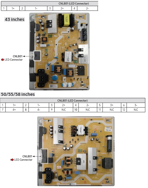
Samsung 43,50,55,58,65 and 75 inch LCD TV power board and back-light inverter troubleshooting
Applicable to UA43RU7100K, UA50RU7100K, UA55RU7100K, UA58RU7100K, UA65RU7100K, UA75RU7100K
Function Control Operation Test
1. Place TV in Power Standby
2. Check LED Status
3. If LED is OFF:
LED 1.7Vdc (pin 8 ) and VCC for 3.3Vdc (pin 3 )
If missing suspect Function Assy/Cable/Main board.
4. If LED is ON:
Switch Operation activates on screen display
If missing:
Key_Input 1 (pin 6 ) change to 0V with a command.
If wrong voltage or no change:
Switch for stuck or miss-operation.
5. Check IR operation with Standard Remote command changes.
6. Check SDA, SCL for effective 3.3Vdc. (after power on)
If missing suspect Function Assy/Cable Assy./Main Assy
Power: SMPS Standby: 43 inches – connector voltages.
50/55/58 inches SMPS connector voltages.
65 inches SMPS connector voltages.
75 inches SMPS connector voltages.
TV power standby test.
1. TV in Standby
 Check Standby LED Indicator.
2. If Not Lit:
 Check AC 120Vac Line.
3. If missing:
 Check AC120Vac Source/Power Cord.
4. If OK:
 Check resistance on SMPS FUSE after first removing AC power cord.
5. If fuse/s are open : replace SMPS.
6. If fus are OK:
  Standby: A13V (Always On) to Main Board.
7. If any missing remove the SMPS connector to the Main Board.
9 Check Standby A13V again.
 If OK replace the Main Board.
 If still missing replace SMPS.
SMPS Power On: 43 inches.
SMPS Power ON: 50/55/58 inches.

SMPS power ON: 65 inches.
SMPS Power ON: 75 inches.
Power ON sequence test.
1. Power TV On.
 Power_On/Off / POWER_ON (pin 8 ) 0.2Vdc (when off) changes to 3.3Vdc (on). [There is an approx 20 second delay from PS-ON to off condition when the TV is powered off, and approx a 2 minute delay when the TV is first plugged into AC Power]
2. If voltage error or no change:
9 Jog Function Control Test.
3. If OK replace Main Board.
9 All A13V supplies for approx. 12.7VDC (pins 3 , 5 , 7 , 9 )
4. If any wrong voltages, remove SMPS connector to Main Board.
9 All A13V again for 12.7VDC (pins 3 , 5 , 7 , 9 )
5. If OK replace Main Board.
6. If still wrong voltage replace SMPS.
    9 OD_ON/OFF (Over Voltage Detect) (pin 4 ) 3.3Vdc : Operating Normal.
7. If 0V or changing, an SMPS or Panel error exists. Perform Backlight Test.
9 BLU_PWM / PWM_BLU (pin 6 ) Backlight On/Off & Dim Control : 1Vdc – 3.3 Vdc depending on backlight dimming level for video.
• If missing or error : Replace Main Board.
SMPS / PANEL BACKLIGHT (Parallel Wired SMPS Panel Connections)
43, 50, 55, & 58 inches
65 and 75 inches.
Backlight Test :
1. Activate Backlights Test : Disconnect Lead Cable from Main to Power Supply.
 Check TV Screen for active backlight LEDs.
2. If No Backlight.
 Minus (Control) pins & Plus (Supply) pins voltages on the Panel Connector. (with fine test probe on left side of connector only for safety)
 If no pin voltages replace SMPS.
3. If Backlights ON BUT PANEL SECTION(S) OFF:
 The Supply Drive (+) pins and (-) pins. All should measure same.
 If a Minus (-) pin measures low (near 0 volts), a string(s) of LEDs are likely open.
  Replace Panel.
 If a (+) pin measures low voltage.
  Defective SMPS.
BACKLIGHT DIMMING PROBLEMS :
• Go to Menu > Picture > Backlight and vary level (0 – 50).
• If no backlight changes observed:
 Panel Connector CNL801 minus (-) pin voltages and PWM_BLU control voltages CNM801 while changing backlight level.
• If minus (-) pin voltages don’t change, and PWM_BLU changes, replace SMPS.
• If PWM_BLU doesn’t change replace Main/T-Con Board.
Backlight Test : In normal TV operating mode, use standard IR Remote or Factory Remote with commands.
Go to (MUTE > 4 > 1 > 9 > EXIT)
Netflix Operation/Connection Issues.
Check Certificate & Netflix ESN Status in Factory Mode.
If Certificate and ESN exists, "CO", "NfO", change the DNS to 8.8.8.8
• If Certificate is missing, "C/" replace the TV’s Main Board.
• If ESN number is missing: NF/ do not replace the Main Board.
- Reset TV Clock and check for correct Time & Date. 
Netflix relies on correct settings.
- Reset Smart Hub. / Reset Apps In Factory Mode.
For Streaming Issues.
Go to TV Web Browser / Go to speedof.me / testmy.net
Check Speed for at least 5 Mbps(HD streaming) / 25 Mbps (4K Streaming).
Check Latency for less than 50ms.
Setting TV into Factory Mode
Factory Remote.
1. Power TV ON.
2. Select TV Source.
3. Info > Factory.
4. Use MENU for return.
Samsung IR Remote.
1. TV Power Standby.
2. Press as follows.
• Remote Buttons (NTSC-MUTE 1 8 2 POWER)
 
PAL  INFO MENU MUTE POWER
Important Items.
• Option (must set Option Bytes when replacing Main Board.)
• Option > Factory Reset (returns TV to out of box condition.)
- Must perform when replacing Main Board or Full One Connect)
Factory Reset : Select Factory Reset.

SVC > Info > ER Count (Important to check for errors.)
- Resets to 0 with Factory Reset.
Check before resetting TV
• SVC > Test Patterns (Use to check / troubleshoot) videos errors.
• Control > EDID (Use to Reset HDMI Operational Errors)
Setting Option Bytes.
1 Enter Factory Mode with Service Remote (only).
2. Check Option Byte Table located on GSPN (Fast Track or Tips).
3. Select Option.
4. Select each item to change.
5. Can Use new Writing Type to enter model (if entered wrong it will not change.)

6. Soft power TV Off to load.
Performing Factory Reset.
Enter Factory Mode.
2. Select Option > Factory Reset
3. TV will power off.
4. Perform ALL TV Settings. (New out of box condition)
Details: UA65RU7100KXXV
Main board

Saturday, October 12, 2019

How to enter service mode - Mitsubishi Laservue DLP projection TV - Service adjustments - Service mode - SMPS Schematic


LASERVUE PROJECTION HDTV V46 CHASSIS 
Light Engine : DLP® (1080p) 
Power Input : AC 120V, 60Hz - 
Tuning : 1 NTSC/ATSC/QAM
Service procedures
Many service functions and adjustments are accessed using the Remote Control.
Option menu
1. Press the <MENU> button on the remote control.
2. Press the buttons <2-4-7-0>. The screen will display the Option Menu. [Service Mode]
Service level initialization.
Service Level Initialization is used to restore all customer menu, video and audio settings to the original factory default condition.
1. Enter the Option Menu <MENU><2-4-7-0>
2. Select “Initialize” and <ENTER>
Deactivate VUDU.
This feature will deactivate the customer’s VUDU on-line subscription. It should be used before TV ownership is changed. NOTE: This feature is independent of the Initialize function.
1. Enter the Option Menu <MENU><2-4-7-0>.
2. Select “Deactivate VUDU” and <ENTER>.
3. The “VUDU Reset” text will momentarily turn red.
4. Press <EXIT> to quit.
5. The TV will register as deactivated the next time it is connected to the internet.
Digital signal strength.
1. Tune to a Digital Channel.
2. From the Option Menu, scroll down and highlight “Digital Signal Strength.”
3. Press <ENTER>. The screen will display the Digital Signal Strength Menu.
SNR Recommended Levels:
8VSB = 16 to 33
64 QAM = 22 to 35
256 QAM = 27 to 38
Reset / Initialization.
Many symptoms that are customer generated, intermittent or cannot be verified can be resolved by using the various Reset and Initialization options. Before visiting the customer’s home ask the customer to 1st perform a System Reset by pressing the <POWER> button on the side panel and holding it for 8 seconds.
 If this does not resolve the issue, they can perform an A/V Reset by pressing the side panel <INPUT> + <VOL UP > buttons at the same time and holding for 10 seconds. Then, if necessary, perform a user level Initialization by pressing <MENU><1-2-3> <ENTER> with the remote.
The customer should be made aware when settings and/or options will be reset.
LED indications and self diagnostics
The front panel Power LED provides an indication of the set’s operation and the possible cause of a malfunction.
Self diagnostics
A blinking red and yellow Status LED will indicate an Error Code that can help determine the cause of a circuit failure.
 The number of Red blinks indicates the value of the MSD (tens digit) of the Error Code.
 The number of Yellow blinks indicates the value of the LSD (ones digit) of the Error Code.
Example: If the Error Code is “37”, the LED will continuously blink Red three times, followed by blinking Yellow seven times.
To perform a System Reset, press and hold the Power button for 10 seconds. Or, unplug the set for 10 seconds then restore power.
After 3 occurrences, the TV will be locked out and will not respond to Power On commands. After repair, use the following procedure to unlock the TV.
1. Perform a System Reset by removing and re-applying AC.
2. Press and hold the side panel <INPUT> + <VOL Dn> buttons at the same time until the Status LED returns to normal (about 5 seconds).
Error code log.
The Error Code Log may be helpful to retrieve the code for an error that occurred in the past.
To access the Error Code Log: Press <MENU> <3-5-6-4>
Code Log Definitions
 PAGE - Current page number
 CURRENT TIME - total hours of operational use.
 USAGE TIME - usage hours when the error occurred.
 CODE - the specific Error Code that occurred.
 STATUS: HAPPENED - Indicates an error was recorded.
Press <CANCEL> to erase the Log.
[The Error Code Log is intended as a reference tool and is not meant to be used as a final determination of a defective part].
Service adjustments.
There are 2 Types of Service Adjustments, electrical and mechanical:
Electrical Adjustments.
  Horizontal and Vertical Centering Adjustment.
  Index Delay Adjustment.
  Geometry Alignment.
  Data Transfer Functions.
Mechanical Adjustment.
  Top Mirror Adjustment.
Electrical adjustments
Specific Adjust Procedures follow
 Service adjustments are performed using the remote control.
 The Service Menu is used for all service adjustments.
 Test Patterns are generated internally.
Activating the Service Menu
1. Press the <MENU> button on a remote control. (The “MENU” display will appear.)
2. Press the buttons <2-4-5-7>. (The Service Menu On Screen Display will appear.)
If no display appears, press <EXIT> and repeat steps 1 and 2.
Test Pattern Activation
1. When in the Service Menu, press Play  to activate the internal test patterns (no indication will be displayed initially). Use FWD and RWD to toggle between patterns.
2. Press Play a second time and use FWD and RWD to access additional patterns.
3. Press Play  again to toggle back to the previous patterns.
Adjustment Selection
When in the Service Menu use the <VIDEO> button to toggle to the adjustment desired as indicated by the number and abbreviation displayed on screen, i.e. “1.HVPOS.”
Adjusting Data
After selecting an adjustment item, use the Navigation UP/DN, LEFT/RIGHT buttons to perform the adjustment.
Saving Data
Press <ENTER> to save the adjustment data. The menu display will turn red for approximately one second. Note: If the circuit adjustment mode is terminated without pressing <ENTER>, changes in adjustment data are not saved.
Data Transfer & Geometry Menu
While in the Service Menu, press the <0> button to activate the Data Transfer & Geometry Menu.
Exiting the Service Menu
Press <EXIT> to quit.
Horizontal and Vertical Position Adjustment
1. Enter the Service Menu <MENU><2-4-5-7> .
2. Select the Geometry Test Pattern shown Play Rewind x2.
3. If necessary, select the adjustment, “1.HVPOS” <VIDEO>.
4. After selecting the HVPOS adjustment item, use the Navigation UP/DN, LEFT/RIGHT buttons to center the display.
  If a Up/Down button is pressed, the vertical position and VPOS adjustment data changes.
  If a Left/Right button is pressed, the horizontal position and HPOS adjustment data changes.
5. Press <ENTER> to save the adjustment data.
TSP Alignment (after Optical Engine replacement)
1. Enter the Service Menu <MENU-<2-4-5-7>.
2. Select the TSP Test Pattern by pressing PLAY once, then FAST FORWARD  or REWIND  until the pattern shown appears.
3. Use the <VIDEO> button to select “2.TSP”.
4. Use the DIRECTION buttons to straighten the horizontal lines, see example.
5. Press <ENTER> to save the adjustment.
Select Calibration Table (after Light Source Unit replacement)
1. In the Customer’s Video Settings Menu select COLOR TEMP: HIGH
2. Enter the Service Menu <MENU-<2-4-5-7>.
3. Use the <VIDEO> button to select the adjustment, “61.BCMH” and note the data value (0, 1, 2, 3 or 4).
4. Select the Green Double Ramp Pattern by pressing PLAY <w> twice, then FAST FORWARD or REWIND  until the pattern below appears.
5. Check the pattern for smoothness of graduation from dark to light and for the presence any vertical contour lines.
6. Use the DIRECTION  buttons to alternately change the Data Value of “61.BCMH” to 0, 1, 2, 3 or 4.
As necessary, press PLAY once to observe the Service Menu on screen display and press PLAY twice to return to the pattern.
7. Select the data value 0, 1, 2, 3 or 4 that gives the best results. No higher data value should be used.
8. Press <ENTER> to save the adjustment.
Manual Geometry Alignment
1. Activate the Service Mode <MENU><2-4-5-7>. From the Service Menu, press the <0> button. The Data Transfer & Geometry Menu will appear.
2. Use the Up/Dn buttons to select “MANUAL GEOMETRY ALIGNMENT” and press <ENTER>.
3. The Manual Geometry Alignment Pattern will appear. See below.
4. Prepare for the alignment by resetting the geometry data. Press <1> then <ENTER>. The previous menu will be displayed. Select “MANUAL GEOMETRY ALIGNMENT” and press <ENTER> again to proceed.
Note 1: Upon entering the Manual Geometry Alignment Mode the first time, the geometry may appear distorted because all factory geometry correction is automatically disabled. Press <EXIT> to quit and re-enable the factory geometry correction. Pressing <1> <ENTER> and <EXIT> will cause the TV to operate with out factory geometry correction (distortion will be present).
[At any time the original factory geometry data can be restored from backup:  
 From the Data Transfer & Geometry Menu <MENU><2-4-5-7><0>, select “RESTORE GEOMETRY DATA FROM BACKUP” <ENTER>.
Phase 1 - 20 Point Geometry Alignment
1. 20 Adjustment Points are indicated by white dots around the edge of the raster. The adjustment position is indicated by a + cursor.
2. Starting from the upper left corner, use the buttons to align the + at each point in a straight line, flush with the bezel as a reference.
Note: Only the cursor will move. The Geometry Pattern will not change.
3. After adjusting each point, use the <uu> button to shift the cursor to the next point clockwise and repeat until all 20 points have been adjusted.
4. After all 20 points are adjusted and the cursor is returned to the original starting point, press <ENTER>.
Correction will be automatically calculated and saved and the Manual Geometry Alignment will be terminated.
5. Press <ENTER> to re-activate the Manual Geometry Alignment. The geometry pattern will appear with the corrections applied.
Phase 3 - 4:3 and 16:9 Alignment
1. With the Manual Geometry Alignment activated, press <VIDEO> to enter the Left 4:3 Alignment Mode. The pattern below will be displayed.
Note: Pressing <VIDEO> will toggle between the Left 4:3, Right 4:3, Top 16:9, Bottom 16:9 and the 20 Point Geometry Alignment modes.
2. In the Left 4:3 Alignment Mode, pressing << or >> will cause the geometry pattern to be displayed with 12 preset amounts of correction. Toggle through them until you find the one with the straightest Blue 4:3 Line.
It may help to count the patterns as you cycle through them. When you find the pattern with the straightest Blue 4:3 Line, press <VIDEO>. The pattern will be displayed with a Right Blue 4:3 Line.
3. In the Right 4:3 Alignment Mode, pressing <<or >> will cause the geometry pattern to be displayed with 12 preset amounts of correction. Toggle through them until you find the one with the straightest Blue 4:3 Line. Again, count the patterns as you cycle through them. When you find the pattern with the straightest line, press <VIDEO>. The Top Red Line will be displayed in the pattern.
4. In the Top 16:9 Alignment Mode, pressing << or >> will cause the geometry pattern to be displayed
with 30 different preset amounts of correction to the Top Red Line. Toggle through them until you find the one with the straightest Red Line. Again, count the patterns as you cycle through them. When you find the pattern with the straightest line, press <VIDEO>. The Center Red Line will be displayed in the pattern.
5. In the Center 16:9 Alignment Mode, pressing <<or >> will cause the geometry pattern to be displayed with 30 different preset amounts of correction to the Center Red Line. Toggle through them until you find the one with the straightest Red Line. Again, count the patterns as you cycle through them. When you find the pattern with the straightest line, press <VIDEO>. The Bottom Red Line will be displayed in the pattern.
6. In the Bottom 16:9 Alignment Mode, pressing <tt> or <uu> will cause the geometry pattern to be displayed with 30 different preset amounts of correction to the Bottom Red Line. Toggle through them until you find the one with the straightest Red Line. When you find the pattern with the straightest line, press <VIDEO>. Press <ENTER> then <EXIT> to exit and save the 4:3 and 16:9 data.
7. Select the Geometry Test Pattern (See HVPOS). If Geometry is acceptable, press <EXIT> to quit.
Data Transfer
Service Data is duplicated and stored in separate EEPROMs in two locations.
  PWB-MAIN - Working data for TV operation
  OPTICAL ENGINE - Backup data
Enter the Service Mode <MENU><2-4-5-7> Select the Data Transfer & Geometry Menu <0>
[[Warning - Only use "SAVE ENGINE AND GEOMETRY SETTING TO BACKUP" after Optical Engine replacement]]
Note: Besides MANUAL GEOMETRY ALIGNMENT, six data transfer choices are listed on screen.
  RESTORE ENGINE DATA FROM BACKUP - copies backup factory adjustments HVPOS, White Balance and Index Delay from the Optical Engine to the PWB-MAIN.
  RESTORE GEOMETRY DATA FROM BACKUP - copies backup factory Geometry Alignment data from the Optical Engine to the PWB-MAIN.
  SAVE ENGINE AND GEOMETRY SETTING TO BACKUP - copies all working data from the PWB-MAIN into backup memory on the Optical Engine.
  BACKUP AND RESTORE ISF SETTINGS - allows the ISF (ADV) video settings to be backed up and restored using an external USB memory device.
  RED ONLY AND GREEN ONLY - displays the video in red or green only.
2. Use the UP/DN buttons to select the item and press <ENTER>.
3. Follow on-screen instructions if given.
4. Press <EXIT> to quit.
After Optical Engine Replacement:
1. Save Engine and Geometry Setting to Backup
After Electrical Chassis (PWB-MAIN) Replacement:
1. Restore Engine Data From Backup
2. Restore Geometry Data From Backup.
3. Restore ISF Settings From Backup (Only if backup USB memory device is available).
V46 SMPS [Power supply] Schematic

Tuesday, October 01, 2019

How to repair Aiwa HVFX5840 stereo video cassette recorder, SMPS schematic, IC voltage chart


Applicable to Aiwa HV-FX7800, HV-FX5850, HV-GX1700, HV-GX1400, HV-GX1100
How to repair and assemble the deck mechanism, Gear wheel alignment, mechanism alignment check, Power board schematic and more
STEREO VIDEO CASSETTE RECORDER <7800/5850>  BASIC VIDEO MECHANISM  D33Y1-4HF/PAL(6721RF0450A)<7800,5850>
VIDEO CASSETTE RECORDER <1700/1400/1100>  BASIC VIDEO MECHANISM  D33Y1-2HD/PAL(6721RF0405A)<1700,1400,1100>
How to disassmeble the deck mechanism: Mechanism parts locations.
[When reassembly perform the procedure in the reverse order]
When reassembling, confirm Mechanism and Mode Switch Alignment Position.
When disassembling, the Parts for Starting No. Should be removed first.
Drum Assembly
1) Unhook the (H1) on the back side of the Chassis and separate the Cap FPC.
2) Remove three Screws (S1) and lift up the Drum Assembly.
3) Remove two Screws (S2) and Separate the Stator of Drum Motor.
4) Remove two Screws (S3) and Separate the Rotor of Drum Motor from the Drum Sub Assembly.
[When reassembling Cap FPC, two Holes of Drum FPC are inserted to the two Bosses of Holder FPC correctly.]
Plate Assembly Top, Holder Assembly CST, Guide CST, Bracket Side(L), Bracket Assembly Door, Arm Assembly F/L & Lever Assembly S/W
Plate Assembly Top
1) Unhook the (H1) and separate the Left Side.
2) Unhook the (H2) and lift up the Plate Assembly Top.
[When reassembling, confirm (A),(B) Part of the Plate Assembly Top is inserted to the (L),(R) Grooves of the Bracket Side(L) and Bracket Assembly Door]
Holder Assembly CST
1) Push the Lever Stopper (R) in the direction of the arrows (A) and move the Holder Assembly CST.
2) Push the Bracket Assembly Door to the right and lift up the Holder Assembly CST along the Guide Groove of the Bracket Assembly Door.
Guide CST
1) Unhook(H3) in the direction of the arrow and separate the left side.
2) Unhook (H4) as above No.1) and disassemble the Guide CST in the direction of the arrow.
Bracket Side(L) Bracket Assembly Door
1) Remove the Screw (S4) and disassemble the Bracket Side(L) in the front.
2) Remove the Screw (S4) and disassemble the Bracket Assembly Door in the front.
Arm Assembly F/L
1) Push the Arm Assembly F/L to the left and lift up it.
[When reassembling, confirm that the Gear(A) of the Arm F/L and the Gear(B) of the Gear Rack F/L are assembled as shown in picture]
Lever Assembly S/W
1) Hook the Spring Lever S/W on (H5).
2) Lift up the left side of the Lever S/W from the Groove(A) of the Chassis.
Arm Assembly Cleaner
1) Break away the (A) part shown above Fig. from the Embossing of the Chassis in the clockwise direction and lift up the Arm Assembly Cleaner.
Head F/E
1) Unhook the two Hooks (H1) on the back side of the Chassis and lift up the Head F/E.
Base Assembly A/C Head
1) Remove the Screw (S5) and lift up the Base Assembly A/C Head.
Brake Assembly Supply
1) Remove the Spring S Brake.
2) Hold the (A) part shown above Fig. A-4-1 and turn to the clockwise direction, and then lift up the Brake Assembly S.
[When reassembling, be careful not to change the Spring with below]
Brake Assembly Take-up
1) Remove the Spring T Brake.
2) Hold the (B) part shown above  and turn to the counterclockwise direction, and then lift up the Brake Assembly T.
[When reassembling, be careful not to change the Spring]
Arm Assembly Tension
1) Remove the Spring Tension.
2) Hold the (C) part shown above Fig.and turn to the clockwise direction, and then lift up the Arm Assembly Tension.
[When reassembling, be careful not to change the Spring]
 Reel Supply  & Reel Take up [S&T]
Lift up the Reel S and Reel T.
When reassembling, be careful not to change the Reel S and Reel T each other.
Lift up the Reel S and Reel T.
When reassembling, be careful not to change the Reel S and Reel T each other.
Support CST
1) Break away the (A) part shown . A-5-1 from the Embossing of the Chassis in the clockwise direction, and lift up the Support CST.
Base Assembly P4
Break away the (B) part shown  A-5-2 from the Embossing of the Chassis in the counterclockwise direction and lift up the Base Assembly P4.
Opener Lid
Break away the (C) Part of the Opener Lid from the Embossing of the Chassis in the Clockwise direction and lift up the Opener Lid.
Arm Assembly T/up
1) Just lift up the Arm Assembly T/UP
[When reassembling, confirm the opener lid is placed on the Hook(H1) of the Arm Assembly T/UP as shown]
Belt Capstan, Motor Capstan
1) Remove the Belt Capstan.
2) Remove three Screws(S6) on the back side of the Chassis and lift up the Motor Capstan.
When reassembling, Confirm the (A), (B) parts of Motor Capstan is located to the (A'), (B') of the Chassis.
Clutch Assembly D33-Y
1) Remove the Washer(W1) and lift up the Clutch Assembly D33-Y.
Lever F/R
1) Unhook the (H1) shown Fig. A-6-4 and lift up the Lever F/R.
[When reassembling, move the (C) part of the Lever F/R up and down, then confirm if it is returned to original position.]
Gear H-Up/D-K or Gear Up/D-K
1) Remove the Washer(W2) and lift up the Gear H-up/D-K.
2) Remove the Spring Up/D.
NOTE
Gear H-Up/D-K is for Hi-Rewind Models.
Gear Up/D-K is for Normal Models except Hi-Rewind Models.
Bracket Assembly Jog ,(Jog shuttle model option)
1) Remove the Screw(S4) and lift up the Bracket Assembly Jog.
Guide Rack F/L, Gear Rack F/L
1) Remove the Screw(S4) and lift up the Guide Rack F/L.
2) Lift up the Gear Rack F/L.
26. Brake Assembly Capstan
(4HD model option)
1) Hook the Spring Capstan on the Hook(H1).
2) Unhook the Hook(H2) and lift up the Brake Assembly Capstan.
[When reassembling, confirm that the Hole(A) of the Brake Assembly Capstan is aligned to the Hole(B) of the Gear Cam.]
Gear Drive, Gear Cam, Gear Connector
1) Remove the Washer(W1) and lift up the Gear Drive.
2) Lift up the Gear Cam.
3) Lift up the Gear Connector.
When reassembling, confirm that the Hole (A) of the Gear Connector is aligned to the Hole (A') of the Chassis
When reassembling, confirm that the Hole (B) of the Gear Cam is aligned to the Hole (B') of the Chassis
When reassembling, confirm that the (C) part of the Gear Cam is aligned to the (D) part of the Gear Drive as shown Fig.
Bracket Assembly L/D Motor
1) Unhook the three Hooks(H1),(H2) and push down the Bracket Assembly L/D Motor.
Gear Sector
1) Remove the Washer(W1) and lift up the Gear Sector.
30. Base Tension, Plate Slider, Lever Tension
1) Remove the Screw(S4) and lift up the Base Tension.
2) Lift up the Plate Slider.
3) Hold the (A) Part of the Lever Tension and turn to the counterclockwise direction, and then lift up the Lever Tension.
[When reassembling, turn the Lever Tension to the clockwise direction in maximum.  Push the plate slide right side to be guided by the shaft.
Gear Assembly P3, Gear Assembly P2
1) Unhook the two Hooks(H1) and lift up the Gear Assembly P3.
2) Unhook the two Hooks(H2) and lift up the Gear Assembly P2.
Base Assembly P3
Base Assembly P2
1) Move the Base Assembly P3 in the direction of the arrow of the Chassis Hole(A) and push down the Base Assembly P3.
2) Move the Base Assembly P2 in the direction of the arrow of the Chassis Hole(B) and push down the Base Assembly P2.
Arm Assembly Idler or Arm Assembly, Idler Jog
1) Unhook the Hook(H3) and push down the Arm Assembly Idler Jog.
NOTE: Arm Assembly Idler is for Normal Models.  Arm Assembly Idler Jog is for Jog Shuttle Models. When reassembling, confirm that the (A) Part of the Gear Assembly P3 is aligned to the (B) Part of the Gear Assembly P2 as shown.
Mechanism Alignment Position Check
1) Turn the Power S/W on and eject the Cassette by pressing the Eject Button.
2) Remove the Top Cover and Plate Assembly Top, visually check if the Gear Cam Hole is aligned with the Chassis Hole as below Fig.
3) IF not, rotate the Shaft of the Loading Motor to either Clockwise or Counterclockwise until the Alignment is as below Fig.
4) Remove the Screw which fixes the Deck Mechanism and Main Frame and confirm if the Gear Cam is aligned with the Gear Drive as below Fig. C-1(A).
5) Confirm if the Mode S/W on the Main P.C.Board is aligned as below Fig. C-1(B).
6) Remount the Deck Mechanism on the Main P.C.Board and check each operation.
Power schematic and voltage chart