Monday, July 09, 2018

UE32ES5500, UE26EH4500 – Samsung LCD TV – firmware update, troubleshooting, PIN reset, calibration and more


Samsung X10+ LED TV - UE32ES5500(5700), UE40ES5500(5700), UE46ES5500(5700)
UE32EH5300, UE40EH5300, UE46EH5300, UE26EH4500, UE22ES5400 
ES5700 : DVB-T/C/S2 Model
When you want to initialize the TV setting, use the 'reset' menu. Initial PIN number : '0-0-0-0
(If you want change the PIN number, use the Change PIN function located 'System-Security' menu.)
After you execute 'Reset' function, All the settings will return to factory default.
If you forget the PIN code, press the remote control buttons in the following sequence in Standby mode, which resets the PIN to 0,0,0,0:
[MUTE 8,2,4, Power ON.]
How to check the SW version
Use the main menu
 Click the "menu" key in remote controller.
 Select Support menu.
 Locate the menu cursor "Software Upgrade" menu.
 Click the "info" key.
 Check the Main SW and SubMicom SW Version.
How to Upgade Main SW and Micom
Insert the USB device containing the firmware upgrade downloaded from Samsung.com into TV.  Be careful not to disconnect the power or the USB drive while upgrades are being applied.  The TV will turn off and turn on automatically after completing the firmware upgrade.  Check the firmware version after the upgrade are complete [the new version will have higher number than the older version].  When the software is upgraded, video and audio setting you have made will return to their default [factory] settings.  It is recommended you to write down your settings before the beginning of the firmware update.  After update is completed, restore the previous settings.
How to Upgrade Main SW
Store the SW program named –T-MST10PDEUC” in USB memory stick.
Connect the USB
Click the Menu key in remote control.
Select Support Menu
Locate the menu cursor :Software Upgrade” menu.
Click the Enter key.
How to Upgrade SubMicom SW
Store the SW program named “SubmicomEU_10***” in USB memory stick.
Connect the USB.
Enter the factory.
Locate the cursor “SVC” menu.
Click Enter key.
Locate the cursor ‘SUBMICOM UPGRADE” menu.
Click on the pictures to magnify
Troubleshooting

This Troubleshooting is based on E5500(5700) Model.

No Power – troubleshooting table and possible fault locations

No video  HDMI 1, 2, 3 – Digital signal – troubleshooting table &  possible fault locations
No video – Tuner_CVBS – Troubleshooting and possible fault  locations
No video – Tuner DTV – troubleshooting and fault locations
No video AV – troubleshooting and fault locations
No video – Component – troubleshooting and fault locations
No sound – Speaker, Headphone out, Optical – troubleshooting and fault locations
Calibration

Sunday, July 01, 2018

Sony HCD SHAKEX3 – factory mode, error codes, Power amplifier schematic


Sony HCD-SHAKEX1/SHAKEX3/SHAKEX7 - DVD RECEIVER
AEP Model. UK Model. Australian Model ---- HCD-SHAKEX1/SHAKEX3
E Model ---- HCD-SHAKEX1/SHAKEX3/SHAKEX7
HCD-SHAKEX1 is the tuner, USB, DVD Player, Bluetooth, NFC and amplifier section in SHAKE-X1D. 
HCD-SHAKEX3 is the tuner, USB, DVD Player, Bluetooth, NFC and amplifier section in SHAKE-X3D. 
HCD-SHAKEX7 is the tuner, USB, DVD Player, Bluetooth, NFC and amplifier section in SHAKE-X7D.
DVD Mechanism Type:   CDM90-DVBU204//M
Laser Pickup:  CMS-S76RFG1 OR CMS-S76RFGP
SHAKE-X7D
Power Output (rated)::  800 W + 800 W (at 8 ohms, 100 Hz, 1% THD)
RMS output power (reference)::  1,200 W + 1,200 W (per channel at 8 ohms, 100 Hz)
SHAKE-X3D
Power Output (rated): 400 W + 400 W (at 4 ohms, 100 Hz, 1% THD)
RMS output power (reference):  600 W + 600 W (per channel at 4 ohms, 100 Hz)
SHAKE-X1D
Power Output (rated):  400 W + 400 W (at 4 ohms, 100 Hz, 1% THD)
RMS output power (reference):  600 W + 600 W (per channel at 4 ohms, 100 Hz)
* Keep the temperature of the soldering iron around 270 °C during repairing.
* Do not touch the soldering iron on the same conductor of the circuit board (within 3 times).
* Be careful not to apply force on the conductor when soldering or unsoldering.
Notes on laser diode emission check
The laser beam on this model is concentrated so as to be focused on the disc reflective surface by the objective lens in the optical pickup block. Therefore, when checking the laser diode emission, observe from more than 30 cm away from the objective lens.
The laser diode in the optical pick-up block may suffer electrostatic break-down because of the potential difference generated by the charged electrostatic load, etc. on clothing and the human body.
During repair, pay attention to electrostatic break-down and also use the procedure in the printed matter which is included in the repair parts.  The flexible board is easily damaged and should be handled with care.
How to Pair this system with a Bluetooth device
1. Press the [Power1] button to turn the power on.
2. Place the Bluetooth device within 1 meter from the system.
3. Press BLUETOOTH on the unit to select Bluetooth function. “BLUETOOTH” appears in the display panel.
4. Hold down BLUETOOTH on the unit for 2 seconds or more. “PAIRING” flashes in the display panel.
5. Perform the pairing procedure on the Bluetooth device.
6. Select the model number of the unit on the display of the Bluetooth device.( For example, select “SONY:SHAKE-X1D or SHAKE-X3D or SHAKE-X7D”.)
If passkey is required on the Bluetooth device, enter “0000”.
7. Perform the Bluetooth connection on the Bluetooth device.
8. When pairing is completed and the Bluetooth connection is established, Bluetooth device name appears in the display panel.
9. To cancel pairing operation, hold down BLUETOOTH on the unit for 2 seconds or more until “BLUETOOTH” appears in the display panel.
How to connect with a Smartphone by one touch (NFC)
Note: The operation in this mode must use a NFC-compatible Smartphone (Smartphone’s with a built-in NFC function [OS: Android 2.3.3 or later, excluding Android 3.x])
1. Press the [Power] button to turn the power on.
2. Download and install the app “NFC Easy Connect”.
Download the free Android app from Google Play by searching for “NFC Easy Connect”.
3. Start the app “NFC Easy Connect” on the Smartphone.
Make sure that the application screen is displayed.
4. Touch the Smartphone to the N-Mark on the system until the Smartphone vibrates.
Complete the connection by following the instructions displayed on the Smartphone.
5. When pairing is completed and the Bluetooth connection is established, the Bluetooth device name appears in the display panel.
How to Play music from a Bluetooth device
For a Bluetooth device
1. Press the [Power] button to turn the power on.
2. Press BLUETOOTH on the unit to select Bluetooth function. “BLUETOOTH” appears in the display panel.
3. Establish connection with the Bluetooth device.  Press BLUETOOTH on the unit to connect to the last connected Bluetooth device.
Perform the Bluetooth connection from the Bluetooth device if the device is not connected.
Once the connection is established, the Bluetooth device name appears in the display panel.
Press =► Depending on the Bluetooth device,
– you may have to press =►  twice.
You may need to start playback of an audio source on the Bluetooth device.
For an NFC-compatible Smartphone
Press the [Power] button to turn the power on.
Touch the Smartphone to the N-Mark on the system to establish the Bluetooth connection.
Start playback of an audio source on the Smartphone. For details on playback, refer to the operating instructions of your Smartphone.
To disconnect the Bluetooth device
For a Bluetooth device
Press BLUETOOTH on the unit. “BLUETOOTH” appears in the display panel.
For an NFC-compatible Smartphone
Touch the Smartphone to the N-Mark on the system again.
To erase all the pairing registration information perform COLD RESET test mode
Test mode
panel test mode
This mode is used to check the fluorescent indicator tube, LEDs, keys, [VOLUME/MULTI CONTROL] knob, model, destination and software version.
Procedure:
1. Press [
<] button and [S3 TUNING ‒ ◄] button simultaneously and hold 3 seconds.
2. All LEDs and segments in fluorescent indicator tube are lighted up. All RGB LEDs are lighted up in white color.
3. When you want to enter to the software version display mode, press [S2
0+] button.
The model information appears on the fluorescent indicator tube.  Press [S20+] button again to view the destination information.
4. During the destination information display, press [S2 0+] button. Each time [S2 0+] button is pressed, the fluorescent indicator tube shows the version of each category software in the following sequence: SC, MTK, OPU, UI, PF, SUB, SYS, CD, CMA, CMB, ST, TA, TM and return back to model information display.
5. When [<] button is pressed while the version numbers are being displayed except model and destination, the date of the software creation appears. When [<] button is pressed again, the display returns to the software version display.
6. Press [S1 0‒] button, the key check mode is activated.
7. In the key check mode, the fluorescent indicator tube displays “K 0 V0”.
Each time a button is pressed, “K” value increases. However, once a button has been pressed, it is no longer taken into account.
“V” value increases in the manner of 0, 1, 2, 3 ... if [VOLUME/ MULTI CONTROL] knob is turned clockwise, or it decreases in the manner of 0, 9, 8, 7 ... if [VOLUME/MULTI CONTROL] knob is turned counterclockwise.
8. When [ENTER] button is pressed after all LEDs and segments in fluorescent indicator tube light up, alternate segments in fluorescent indicator tube and LEDs would light up, all RGB LEDs would light up in RED color. If you press [ENTER] button again, another half of alternate segments in fluorescent indicator tube and LEDs would light up, all RGB LEDs would light up in GREEN color. Pressing [ENTER] button again would cause all segments in fluorescent indicator tube and LEDs light up, all RGB LEDs would light up in blue color.
Pressing [ENTER] button again would turn off all segments in fluorescent indicator tube and all LEDs including RGB LEDs.
9. To release from this mode, press the buttons in the same manner as step 1, or disconnect the power cord.
User reset
The user reset clears all data including preset data stored in the data flash to initial conditions exclude history mode data.
Procedure:
1. Press the Power/1button to turn on the system.
2. Press [DJ OFF] button and [S4 TUNING +>] button simultaneously for 3 seconds.
3. “RESET” appears on the fluorescent indicator tube. After that, the fluorescent indicator tube becomes blank for a while, and the system is reset.
Cold reset
The cold reset clears all data including preset data stored in the
data flash to initial conditions included history mode data. Execute this mode when returning the set to the customer.
Procedure:
1. Press [Power1] button to turn on the system.
2. Press [
<] button and [S4 TUNING +►►] button simultaneously for 3 seconds.
3. “COLD RESET” appears on the fluorescent indicator tube.
After that, the fluorescent indicator tube will display “SONY DEMO”. The set will automatically Power ON and Power OFF again, and the system is reset.
** Disc tray lock mode
This mode let you lock the disc tray. When this mode is activated, the disc tray will not open when [Eject] button is pressed. The message “LOCKED” will be displayed on the fluorescent indicator tube.
This mode only applied when there is disc on the tray.
Procedure:
1. Press [Power1] button to turn on the system.
2. Select DVD/CD function.
3. Press [DJ OFF] button and [ISOLATOR] button simultaneously and hold down until “LOCKED” or “UNLOCKED” displayed on the fluorescent indicator tube (around 5 seconds).
Bluetooth pairing history clear
It can clear the Bluetooth pairing history.
Procedure:
1. Press the [Power1] button to turn the power on.
2. Press the [BLUETOOTH] button to turn the Bluetooth function.
3. Press [DJ OFF] button and [
0‒] button simultaneously for 3 seconds.
4. The message “BT HISTORY” → “CLEAR” is displayed on the fluorescent indicator tube, and the pairing history of Bluetooth is cleared.
History mode
This mode is used to check important data stored in the system when PROTECTOR happen.
Procedure:
1. During demo mode, press [
<] button and [S2 0+] button for 5 seconds to mode into history mode.
2. Press the [S4 TUNING +►►|] button or [S3 TUNING ‒ |◄◄ ] button to check history data stored.
To release from History Mode.
To release from this mode, press [Power] button.
Protect Type Description
01 = The over current condition to MOSFET occurs by defect of MOSFET or defect of PS output line
OR
Unusual heat up of MOSFET by improper assembly of heat sink, destruction of MOSFET etc
02 = Defect of thermistor IC or charging circuit used by SPM (Sound Pressure Management) system.
03 = Defect of power supply circuit to AMP. There is possibility of unusual power supply of any of the AMP IC or Pre-amplifier.
04 = DC appears in SP terminal by defect of AMP IC and MOSFET.
05 = Defect of DC FAN and DC FAN driver circuit.
If speaker does not have output even if the set status is not in PROTECT mode, the following defect might be possible
RESET defect > Reset signal status from micom is not ‘H’
4CH D-Amp board schematic and pwb
DVD service mode
• This mode let you make diagnosis and adjustment easily by using the remote commander and the TV. The instructions, diagnostic results, etc. are given on the on-screen display.
Test disc list
Be sure to use the DVD disc that matches the signal standards of your region.
• CD
YEDS-18 (Part No.: 3-702-101-01)
PATD-012 (Part No.: 4-225-203-01)
HLX-A1 (Part No.: J-2501-307-A)
• DVD SL (Single Layer)
NTSC : HLX-503 (Part No.: J-6090-069-A)
HLX-504 (Part No.: J-6090-088-A)
HLX-513 (Part No.: J-2501-305-A)
PAL : HLX-506 (Part No.: J-6090-077-A)
• DVD DL (Double Layer)
NTSC : HLX-501 (Part No.: J-6090-071-A)
HLX-505 (Part No.: J-6090-089-A)
HLX-514 (Part No.: J-2501-306-A)
PAL : HLX-507 (Part No.: J-6090-078-A)
To enter to DVD Service Mode
Press the [Power] button to turn on the system.
2. Press [FUNCTION +] or [FUNCTION ‒] at remote commander to select DVD/CD function.
3. Press the [SPEAKER LIGHT] button and [ENTER] button simultaneously and hold 3 seconds.
4. The message “SERVICE IN” appears on the fluorescent indicator tube.
The display of the “Model Name” of the “Remocon Diagnosis Menu” change with the model and the destination appears on screen display. Refer to below on the model name.
SHAKE-X1D : TETSUJIN
SHAKE-X3D : RAIJIN
SHAKE-X7D : RYUJIN
5. To execute each function, press its number by using numeric button on the remote commander.
6. To release from this mode, press the [Power] button to turn off the system.
Execute IOP Measurement
In order to execute IOP measurement, the following standard procedures must be followed.
1. From the Top Menu of Remocon Diagnosis Menu, select “2. Drive Manual Operation” by pressing the [2] button on the remote commander. The following screen appears on the onscreen display.
2. Select “3. Manual Adjustment” by pressing the [3] button on the remote commander. The following screen appears on the on-screen display.
3. Select “6. Iop:” by pressing the [6] button on the remote commander.
4. Wait until a hexadecimal number appears in the on-screen display.
5. Convert data from hexadecimal to decimal by using conversion table.
6. Please find the label on the rear of the BU (Base Unit).  The default IOP value is written in the label.
7. Subtract between these two values.
8. If the remainder is smaller than 93 (decimal), then it is OK.  However if the value is higher than 93, then the BU is defective and need to be change.
9. Press the [RETURN] button on the remote commander to return to previous menu.
10. Press the [0] button on the remote commander to return to the Top Menu of Remocon Diagnosis Menu.
11. Press the [Power] button to turn off the system.
Check Emergency History
From the Top Menu of Remocon Diagnosis Menu, select “3. Emergency History” by pressing the [3] button on the remote commander.
2. You can check the total time when the laser is turned on during playback of DVD and CD from the above menu. The maximum time, which can be displayed are 999h 59min.
3. You can check the error code of latest 10 emergency history from the above menu. To view the previous or next page of emergency history, press the [|<<] button or [>>|] button on the remote commander. The error code consists of “Error
Code”, “Parameter of error code” and “Time of error code”
The meaning of error codes.
01: Communication error (No reply from syscon)
02: Syscon hung up
03: Power OFF request when syscon hung up
19: Thermal shutdown
24: MoveSledHome error
25: Mechanical move error (5 Changer)
26: Mechanical move stack error
30: DC motor adjustment error
31: DPD offset adjustment error
32: TE balance adjustment error
33: TE sensor adjustment error
34: TE loop gain adjustment error
35: FE loop gain adjustment error
36: Bad jitter after adjustment
40: Focus NG
42: Focus layer jump NG
51: Spindle stop error
52: Open kick spindle error
60: Focus on error
61: Seek fail error
62: Read Q data/ID error
70: Lead in data read fail
71: TOC read time out (CD)
80: Can’t buffering
81: Unknown media type.
To clear the Laser Hours
Press the [DISPLAY] button and then press the [CLEAR]  button. The data for both CD and DVD data are reset.
To clear the Emergency History
Press the [DVD TOP MENU] button and then press the [CLEAR] button.
The error code for all emergency history would be reset.
To clear the Initialize Setup Data
Press the [DVD/TUNER MENU] button and then press the [CLEAR] button on the remote commander.
To return to the Top Menu of Remocon Diagnosis Menu
Press the [0] button on the remote commander.
To check the version information
From the Top Menu of Remocon Diagnosis Menu, select “4. Version information” by pressing the [4] button on the remote commander.
To return to the Top Menu of Remocon Diagnosis Menu, press the [0] button on the remote commander.
Electro help - Service Modes, Circuit Diagrams, Firmware Update procedure, Disassemble procedure, Universal remote control set-up codes, Troubleshooting and more....

Friday, June 29, 2018

Emerson EWC27T4, Sylvania 6727DE and Symphonic 27 inch TV-DVD-VCR combo – service mode and adjustments, SMPS schematic Firmware update

How to enter the service mode, how to make a service remote control, Universal remote control set-up codes for Emerson, sylvania and Symphonic CTVs
To Enter the Service Mode
Optical sensors system is used for Tape Start and End Sensor on this equipment. Read this carefully and prepare as described before starting to service; otherwise, the unit may operate unexpectedly.
Cover Q202 (START SENSOR) and Q201 (END SENSOR) with Insulation Tape or enter the service mode to activate Sensor Inhibition automatically.
Note: Avoid playing, rewinding or fast forwarding the tape to its beginning or end, because both Tape End Sensors are not active.
Service Mode
1. Turn power on.
2. Use service remote control unit and press "DISC MENU" key.
3. When entering the service mode, one of the numbers (1, 2 or 4) will display at corners of the screen.
4. During the service mode, electrical adjustment mode can be selected by remote control key. (Service remote control unit).
How to make service remote control unit
Prepare normal remote control unit
(Part No. NE222UD --- [ 6727DE ])
(Part No. NE223UD --- [ EWC27T4 ])
Remove 4 screws from the back lid.
Cut off pin 10 of the remote control microprocessor and short circuit pins 10 and 17 of the microprocessor with a jumper wire.
To Set up the Service mode
Use the service remote control unit.
2. Turn the power on. (Use main power on the TV unit.)
3. To enter the TV mode, press "CH o / p" button on the TV unit.
4. Press "DISC MENU" button on the service remote control unit. Version of micro computer will display on the CRT.

X-Ray protection test should be done when replacing any parts of this chassis.
1. Short both ends of R592 (on Sub CBA).
2. Confirm that the main power turns off.
3. If the main power does not turn off, then replace the following parts (D591, Q591, R592, R593, R594 and IC201)
DC 120V (+B) Adjustment
Symptom of Misadjustment: The picture is dark and unit does not operate correctly.
Note: D613 Cathode (+B), HEAT SINK, VR601 --- Main CBA
1. Connect the unit to AC Power Outlet.
2. Connect DC Volt Meter to D613 Cathode (+B) and HEAT SINK (GND).
3. Adjust VR601 so that the voltage of D613 Cathode (+B) becomes +120±1.0V DC.
CONTRAST, COLOR, TINT and V-TINT Data Values.
Enter the Service mode
2. Press "PICTURE" button on the service remote control unit. Display changes "BRT," "CNT," "COL," "TNT," and "V-TNT" cyclically when "PICTURE" button is pressed.
CONTRAST (CNT)
1. Press "PICTURE" button on the service remote control unit. Then select "CONTRAST (CNT)" display.
2. Press "CH Up/Dn” buttons on the service remote control unit so that the value of "CONTRAST (CNT)" becomes 90.
COLOR (COL)
1. Press "PICTURE" button on the service remote control unit. Then select "COLOR (COL)" display.
2. Press "CH Up/Dn" buttons on the service remote control unit so that the value of "COLOR (COL)" becomes 58
TINT (TNT)
1. Press "PICTURE" button on the service remote control unit. Then select "TINT (TNT)" display.
2. Press "CH Up/Dn" buttons on the service remote control unit so that the value of "TINT (TNT)" becomes 57.
V-TINT (V-TNT)
1. Press "PICTURE" button on the service remote control unit. Then select "V-TINT (V-TNT)" display.
2. Press "CH Up/Dn" buttons on the service remote control unit so that the value of "V-TINT (V-TNT)" becomes 56.
Note: BRIGHT data value does not need to be adjusted at this moment.
Setting for Y DL Time TV, Y DL Time EXT, Y SW LPF, Black Stretch Off, Black Stretch CONT and C. Angle Data Values
1. Enter the Service mode.
2. Y DL Time TV Adjustment: Press "0" button on the service remote control unit twice to show "D-T TV" on the display.
Y DL Time EXT Adjustment: Press "0" button on the service remote control unit three times to show "D-T EXT" on the display.
Y SW LPF Adjustment: Press "0" button on the service remote control unit four times to show "Y SW" on the display.
Black Stretch Off Adjustment: Press "0" button on the service remote control unit five times to show "B-S" on the display.
Black Stretch CONT Adjustment: Press "0" button on the service remote control unit six times to show "BS2" on the display.
C. Angle Adjustment: Press "0" button on the service remote control unit seven times to show "CANG" on the display.
3. Y DL Time TV Adjustment: Select "2" by pressing "CH Up/Dn" buttons on the service remote control.
Y DL Time EXT Adjustment: Select "2" by pressing "CH Up/Dn" buttons on the service remote control.
Y SW LPF Adjustment: Select "0" by pressing "CH Up/Dn" buttons on the service remote control.
Black Stretch Off Adjustment: Select "OFF" by pressing "CH Up/Dn" buttons on the service remote control.
Black Stretch CONT Adjustment: Select "0" by pressing "CH Up/Dn" buttons on the service remote control.
 Angle Adjustment: Select "103" by pressing "CH Up/Dn" buttons on the service remote control.
Setting for CD-VOL, DVD-BRT and DVD-SHARP Data Values
1. Enter the Service mode.
2. CD-VOL Adjustment: Press "VOL UP" button on the service remote control unit once to show "CD VOL" on the display.
DVD-BRT Adjustment: Press "VOL UP" button on the service remote control unit twice to show "DVD BRT" on the display.
DVD-SHARP Adjustment: Press "VOL UP" button on the service remote control unit three times to show "DVD SHP" on the display.
3. CD-VOL Adjustment: Select "7" by pressing "CH Up/Dn" buttons on the service remote control.
DVD-BRT Adjustment: Select "0" by pressing "CH Up/Dn" buttons on the service remote control.
DVD-SHARP Adjustment: Select "0" by pressing "CH Up/Dn" buttons on the service remote control.
H fo Adjustment
Purpose: To get correct horizontal position and size of screen image.
Symptom of Misadjustment: Horizontal position and size of screen image may not be properly displayed.
Note: R583 --- Sub CBA
1. Connect frequency counter to R583.
2. Operate the unit for at least 20 minutes.
3. Enter the Service mode. Press "2" button on the remote control unit and select HADJ mode.
4. Press "CH Up/Dn" buttons on the remote control unit so that the display will change "0" to "7."
5. At this moment, choose display "0" to "7" when the frequency counter display is closest to 15.734kHz±300Hz.
6. Turn the power off and on again.
Cut-off Adjustment
Purpose: To adjust the beam current of R, G, B, and screen voltage.
Symptom of Misadjustment: White color may be reddish, greenish or bluish.
Notes: Screen Control --- FBT (Sub CBA), FBT= Fly Back Transformer,
Use the Remote Control Unit.
1. Degauss the CRT and allow the unit to operate for 20 minutes before starting the alignment.
2. Input the Black raster signal from RF input.
3. Enter the Service mode.
4. Press the "VOL DN" button.
(Press "VOL DN" then display will change CUT OFF/
DRIVE and 7Fh adjustment).
5. Choose CUT OFF/DRIVE mode then press "1" button. This adjustment mode is CUT OFF (R).
6. Increase the screen control so that the horizontal line just appears on the CRT.
7. Press the "CH Up/Dn" button until the horizontal line becomes white.
8. Choose CUT OFF/DRIVE mode then press "2" button. This adjustment mode is CUT OFF (G). Press "CH Up/Dn" until the horizontal line becomes white.
9. Choose CUT OFF/DRIVE mode then press "3" button. This adjustment mode is CUT OFF (B). Press "CH Up/Dn" until the horizontal line becomes white.
10.Turn the power off and on again.
H. Size Adjustment
Purpose: To obtain correct size of screen image.
Symptom of Misadjustment: Size of screen image may not be properly displayed.
Note: VR531 --- Sub CBA
1. Input Monoscope pattern.
2. Adjust VR531 so that the size of Monoscope pattern are equal to each other. (90+1%/-5%)
H. Pincushion Adjustment
Purpose: To obtain straight line on the screen.
Symptom of Misadjustment: Straight line image may not be properly displayed.
Note: VR530 --- Sub CBA
1. Input Cross hatch pattern.
2. Adjust VR530 so that the lines of the Cross hatch pattern become straight.
White Balance Adjustment
Purpose: To mix red, green and blue beams correctly for pure white.
Symptom of Misadjustment: White becomes bluish or reddish.
Use service remote control unit
1. Operate the unit more than 20 minutes.
2. Face the unit to the east. Degauss the CRT using a degaussing coil.
3. Input the White Raster (APL 100%).
4. Set the color analyzer to the CHROMA mode and after zero point calibration, bring the optical receptor to the center on the tube surface (CRT).
5. Enter the Service mode. Press "VOL DN" button on the service remote control unit and select "C/D" mode. (Display changes "C/D" and "7F" cyclically when "VOL DN" button is pressed.)
6. Press "4" button on the service remote control unit for Red adjustment. Press "5" button on the service remote control unit for Blue adjustment.
7. In each color mode, press "CH Up/Dn" button to adjust the values of color.
8. Adjust Red and Blue color so that the temperature becomes 9200K (x: 286 / y: 294) ±3%.
9. At this time, re-check that horizontal line is white. If not, re-adjust Cut-off Adjustment until the horizontal line becomes pure white.
10. Turn off and on again to return to normal mode. Receive APL 100% white signal and confirm that Chroma temperatures become 9200K (x: 286 / y: 294) ±3%.
Note: Confirm that Cut Off Adj. is correct after this adjustment, and attempt Cut Off Adj. if needed.
Sub-Brightness Adjustment
Purpose: To get proper brightness.
Symptom of Misadjustment: If Sub-Brightness is incorrect, proper brightness cannot be obtained by adjusting the Brightness Control.
Note: SMPTE Setup level --- 7.5 IRE
1. Enter the Service mode.
Then input SMPTE signal from RF input.
2. Press "PICTURE" button. (Press "PICTURE" button then display will change BRT, CNT, COL, TNT, and V-TNT). Select BRT and press "CH Up/Dn" buttons so that the bar is just visible.
3. Turn the power off and on again.
Focus Adjustment
Purpose: Set the optimum Focus.
Symptom of Misadjustment: If Focus Adjustment is incorrect, blurred images are shown on the display.
Note: Focus VR --- FBT (Sub CBA), FBT= Fly Back Transformer
1. Operate the unit more than 30 minutes.
2. Face the unit to the East and degauss the CRT using a degaussing coil.
3. Input the monoscope pattern.
4. Adjust the Focus Control on the FBT to obtain a clear picture.
Position Adjustment
Purpose: To obtain correct horizontal position and size of screen image.
Symptom of Misadjustment: Horizontal position and size of screen image may not be properly displayed.
Enter the Service mode.
1. Press "8" button on the remote control unit and select H-P mode.
2. Input monoscope pattern.
3. Press "CH Up/Dn" buttons on the remote control unit so that the left and right side of the monoscope pattern are equal to each other.
4. Turn the power off and on again.
V. Shift Adjustment
Purpose: To obtain correct vertical position of screen image.
Symptom of Misadjustment: If V. position is incorrect, vertical position of image on the screen may not be properly displayed.
Enter the Service mode.
1. Press "9" button on the remote control unit and select V-P mode. (Press "9" button then display will change to V-P and V-S).
2. Input monoscope pattern.
3. Press "CH Up/Dn" buttons on the remote control unit so that the top and bottom of the monoscope pattern are equal to each other.
V. Size Adjustment
Purpose: To obtain correct vertical height of screen image.
Symptom of Misadjustment: If V. Size is incorrect, vertical height of image on the screen may not be properly displayed.
Enter the Service mode.
1. Press "9" button on the remote control unit and select V-S mode. (Press "9" button then display will change to V-P and V-S).
2. Input monoscope pattern.
3. Press "CH Up/Dn" buttons on the remote control unit so that the monoscope pattern is 90±5% of display size and the circle is round.
Head Switching Position Adjustment (this is an important adjustment)
Purpose: Determine the Head Switching Position during Playback.
Symptom of Misadjustment: May cause Head Switching Noise or Vertical Jitter in the picture.
Note: Unit reads Head Switching Position automatically and displays it on the screen (Upper Left Corner).
1. Playback test tape (FL8A, FL8N).
2. Enter the Service mode.
Then press the number "5" button on the remote control unit.
3. The Head Switching position will display on the screen; if adjustment is necessary follow step 4.  6.5H(412.7µs) is preferable.
4. Press "CH UP" or "CH DN" button on the remote control unit if necessary. The value will be changed in 0.5H steps up or down. Adjustable range is up to 9.5H. If the value is beyond adjustable range, the display will change as:
Lower out of range: 0.0H
Upper out of range: -.-H
5. Turn the power off and on again.
The following 2 adjustments normally are not attempted in the field. They should be done only when replacing the CRT then adjust as a preparation.
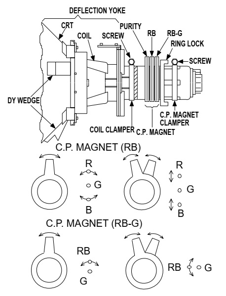
Purity Adjustment
Purpose: To obtain pure color.
Symptom of Misadjustment: If Color Purity Adjustment is incorrect, large areas of color may not be properly displayed.
This becomes RED COLOR if the 7KEY is pressed while in service mode.
1. Set the unit facing east.
2. Operate the unit for over 30 minutes before adjusting.
3. Fully degauss the unit using an external degaussing coil.
4. Set the unit to the AUX mode which is located before CH2 then input a red raster from video in.
5. Loosen the screw on the Deflection Yoke Clamper and pull the Deflection Yoke back away from the screen.
6. Loosen the Ring Lock and adjust the Purity Magnets so that a red field is obtained at the center of the screen. Tighten Ring Lock.
7. Slowly push the Deflection Yoke toward the bell of the CRT and set it where a uniform red field is obtained.
8. Tighten the clamp screw on the Deflection Yoke.
Convergence Adjustment
Purpose: To obtain proper convergence of red, green and blue beams.
Symptom of Misadjustment: If Convergence Adjustment is incorrect, the edge of white letters may have color edges.
1. Set the unit to the AUX mode which is located before CH2 then input a dot or crosshatch pattern.
2. Loosen the Ring Lock and align red with blue dots or crosshatch at the center of the screen by rotating (RB) C.P. Magnets.
3. Align red / blue with green dots at the center of the screen by rotating (RB-G) C.P. Magnet.
4. Fix the C.P. Magnets by tightening the Ring Lock.
5. Remove the DY Wedges and slightly tilt the Deflection Yoke horizontally and vertically to obtain the best overall convergence.
6. Fix the Deflection Yoke by carefully inserting the DY Wedges between CRT and Deflection Yoke.
FIRMWARE RENEWAL
Turn the power on and press [SELECT] button on the remote control unit to put the DVD player into DVD mode. Then remove the disc on the tray.
(It is possible to move to F/W version up mode only when the DVD player is in DVD mode with the tray opened.)
2. To put the DVD player into F/W version up mode, press [9], [8], [7], [6], and [SEARCH MODE] buttons on the remote control unit in that order.
The DVD player can also enter the version up mode with the tray open. In this case, Fig. a will be shown on the screen while the tray is open.
3. Load the disc for version up.
4. The DVD player enters the F/W version up mode automatically. Fig. c appears on the screen. If you enter the F/W for different models, “Disc Error” will appear on the screen, then the tray will open automatically.
The appearance shown in (*2) of Fig. c is described as follows:

State
Appearance
No.
Reading...
Sending files into the memory
1
Erasing...
Erasing previous version data
2
Programming...
Writing new version data
3
5. After programming is finished, the tray opens automatically. Fig. e appears on the screen and the checksum in (*3) of Fig. e
At this time, no buttons are available.
6. Remove the disc on the tray.
7. Press [SELECT] button on the remote control unit to go to TV mode, or press [POWER] button on the unit to turn the power off.
8. Press [SELECT] button on the remote control unit to put the DVD player into DVD mode again.
9. Press [1], [2], [3], [4], and [DISPLAY] buttons on the remote control unit in that order.  Fig. g appears on the screen.
10.Press [CLEAR] button on the remote control unit.  Fig. h appears on the screen.
When “OK” appears on the screen, the factory default will be set. Then the firmware renewal mode is complete.
11.To exit this mode, press [CH UP/DOWN] or [SELECT] button to go to TV mode, or press [POWER] button to turn the power off.
Fixed Voltage (or Auto voltage selectable) power supply circuit is used in this unit.
If Main Fuse (F2601) is blown, first check to see that all components in the power supply circuit are not defective before you connect the AC plug to the AC power supply. Otherwise it may cause some components in the power supply circuit to fail.
SMPS circuit diagram [Schematic]
The deck mechanism assembly is mounted on the Main CBA directly, and SW211 (REC-SAFETY SW) is mounted on the Main CBA. When deck mechanism assembly is removed from the Main CBA due to servicing, this switch cannot be operated automatically.
1. To eject the tape, press the "STOP/EJECT" button on the unit (or Remote Control).
2. When you want to record during the Service mode, press the "Rec" button while depressing SW211 (REC-SAFETY SW) on the Main CBA.

Universal remote control code list
EMERSON:  0004 0042 0049 0065 0101 0113 0119 0145 0152 0166 0191 0214 0215 0225 0324 0378 0421 0456 0460 0604 0611 0654
SYLVANIA:  0392
SYMPHONIC:  0392 0459 0510 0447 0810 0354

Monday, June 18, 2018

32PFL3406-98 – Philips Ebony LCD TV – Service mode, adjustments procedure, Power Board schematic


If a board is defective, consult your repair personal to decide if the board has to be exchanged or if it should be repaired on component level.  If your service technician says the board should be exchanged completely, do not solder on the defective board. Otherwise, it cannot be returned to the O.E.M. supplier for back charging.
Service Modes, Error Codes
The Service Mode feature is split into four parts:
• Service Default Mode (SDM).
• Service Alignment Mode (SAM).
• Customer Service Mode (CSM).
• Computer Aided Repair Mode (ComPair)
Service Default Mode (SDM)
Set the TV in SDM mode in order to be able to create a predefined setting for measurements to be made. In this platform, a simplified SDM is introduced (without protection override and without tuning to a predefined frequency).
How to Activate SDM
To activate SDM, use the following methods:
• Press the following key sequence on the RC transmitter: “062596”, directly followed by the “MENU” button.
Note: It is possible that, together with the SDM, the main menu will appear. To switch it “off”, push the “MENU” button again.
After activating this mode, “SDM” will appear in the upper left corner of the screen (when a picture is available)
On Screen Menu
After activating SDM, the following items are displayed, with “SDM” in the upper right corner of the screen to indicate that the television is in Service Default Mode. Menu items and explanation:
• xxxxx Operating hours (in decimal).
• AAAAAB X.YY See paragraph Software Identification, Version, and Cluster for the SW name definition.
• ERR Shows all errors detected since the last time the buffer was erased in format <xxx> <xxx> <xxx> <xxx> <xxx> (five errors possible).
• OP Used to read-out the option bytes. Ten codes (in two rows) are possible.
How to navigate
As this mode is read only, there is not much to navigate. To switch to other modes, use one of the following methods:
• Command MENU from the user remote will enter the normal user menu (brightness, contrast, colour, etc...) with “SDM” OSD remaining, and pressing MENU key again will return to the last status of SDM again.
• To prevent the OSD from interfering with measurements in SDM, command “OSD” or “i+” (“STATUS” or “INFO” for NAFTA and LATAM) from the user remote will toggle the OSD “on/off” with “SDM” OSD remaining always “on”.
How to Exit SDM
• Switch the set to Stand-by, by pressing the standby button on the remote control transmitter or on the television set.
• Via a standard customer RC-transmitter: key in “00”-sequence.
Note: If the TV is switched “off” by a power interrupt while in SDM, the TV will show up in the last status of SDM menu as soon as the power is supplied again. The error buffer will not be cleared.
Service Alignment Mode (SAM)
Purpose
• To modify the NVM.
• To display/clear the error code buffer.
• To perform alignments.
How to Activate SAM
To activate SAM, use one of the following methods:
• Press the following key sequence on the remote control transmitter: “062596”, directly followed by the “OK” button.
Do not allow the display to time out between entries while keying the sequence.
• Or via ComPair.
After entering SAM, the following items are displayed, with “SAM” in the upper right corner of the screen to indicate that the television is in Service Alignment Mode.
How to Navigate
• In the SAM menu, select menu items with the UP/DOWN keys on the remote control transmitter. The selected item will be indicated. When not all menu items fit on the screen, use the UP/DOWN keys to display the next/previous menu items.
• With the “LEFT/RIGHT” keys, it is possible to:
– (De) activate the selected menu item.
– (De) activate the selected sub menu.
– Change the value of the selected menu item.
• When you press the MENU button twice while in top level SAM, the set will switch to the normal user menu (with the SAM mode still active in the background). To return to the SAM menu press the MENU button.
• The “INFO [i+]” key from the user remote will toggle the OSD “on/off” with “SAM” OSD remaining always “ON".
• Press the following key sequence on the remote control transmitter: “062596” directly followed by the MENU button to switch to SDM (do not allow the display to time out between entries while keying the sequence).
Remarks: new RC will not have I+ button, but function still remain.
How to Store SAM Settings
To store the settings changed in SAM mode (except the RGB ALIGN settings), leave the top level SAM menu by using the POWER button on the remote control transmitter or the television set. The mentioned exceptions must be stored separately via the STORE button.
How to Exit SAM
Use one of the following methods:
• Switch the set to STANDBY by pressing the mains button on the remote control transmitter or the television set.
• Via a standard RC-transmitter, key in “00” sequence.
Note: When the TV is switched “off” by a power interrupt while in SAM, the TV will show up in “normal operation mode” as soon as the power is supplied again. The error buffer will not be cleared.
Blind SAM Display Option Code Selection
When after an SSB or display exchange, the display option code is not set properly, it will result in a TV with “no display”.
Therefore, it is required to set this display option code after such a repair.
To do so, press the following key sequence on a standard RC transmitter: “062598” directly followed by MENU and “xxx”, where “xxx” is a 3 digit decimal value of the panel type: see column “Display Code” below:
When the value is accepted and stored in NVM, the set will switch to Stand-by, to indicate that the process has been completed.
During this algorithm, the NVM-content must be filtered, because several items in the NVM are TV-related and not SSB related (e.g. Model and Prod. S/N). Therefore, “Model” and “Prod. S/N” data is changed into “See Type Plate”. In case a call centre or consumer reads “See Type Plate” in CSM mode, he needs to look to the side/bottom sticker to identify the set, for further actions.
Error Codes
Error codes are required to indicate failures in the TV set. In principle a unique error code is available for every.
• Activated (SW) protection.
• Failing I2C device.
• General I2C error.
The last five errors, stored in the NVM, are shown in the Service menu’s. This is called the error buffer.
The error code buffer contains all errors detected since the last time the buffer was erased. The buffer is written from left to right. When an error occurs that is not yet in the error code buffer, it is displayed at the left side and all other errors shift one
position to the right.
An error will be added to the buffer if this error differs from any error in the buffer. The last found error is displayed on the left.
An error with a designated error code never leads to a deadlock situation. It must always be diagnosable (e.g. error buffer via OSD or blinking LED or via ComPair).
In case a failure identified by an error code automatically results in other error codes (cause and effect), only the error code of the MAIN failure is displayed.
Errors code information:
• Error 000: No problem.
• Error 011: I2C bus error. When this error occurs, the TV will not start up due to the blocked bus.
• Error 012: Tuner error. There is no I2C communication towards the tuner after start-up.
• Error 013: Panel VCC error. This voltage is made in the power supply and results in protection in case of absence.
How to Clear the Error Buffer
You can read the error buffer in three ways:
• On screen via the SAM/SDM/CSM (if you have a picture).
Example:  – ERROR: 0 0 0 0 0: No errors detected.
– ERROR: 6 0 0 0 0: Error code 6 is the last and only detected error.
– ERROR: 9 6 0 0 0: Error code 6 was detected first and error code 9 is the last detected (newest) error.
• Via the blinking LED procedure (when you have no picture)
Errors code information:
• Error 000: No problem.
• Error 011: I2C bus error. When this error occurs, the TV will not start up due to the blocked bus.
• Error 012: Tuner error. There is no I2C communication towards the tuner after start-up.
• Error 013: Panel VCC error. This voltage is made in the power supply and results in protection in case of absence.
How to Clear the Error BuffeThe error code buffer is cleared in the following cases:
• By using the CLEAR command in the SAM menu.
• By using the following key sequence on the remote control transmitter: “062599” directly followed by the OK button.
• If the contents of the error buffer have not changed for 50 hours, the error buffer resets automatically.
Note: If you exit SAM by disconnecting the mains from the television set, the error buffer is not reset.
The Blinking LED Procedure
The software is capable of identifying different kinds of errors.
Because it is possible that more than one error can occur over time, an error buffer is available, which is capable of storing the last five errors that occurred. This is useful if the OSD is not working properly.
Errors can also be displayed by the blinking LED procedure.
The method is to repeatedly let the front LED pulse with as many pulses as the error code number, followed by a period of 1.5 seconds in which the LED is “off”. Then this sequence is repeated.
Example (1): error code 4 will result in four times the sequence LED “on” for 0.25 seconds / LED “off” for 0.25 seconds. After this sequence, the LED will be “off” for 1.5 seconds. Any RC command terminates the sequence. Error code LED blinking is
in red color
Example (2): the content of the error buffer is “12 9 6 0 0” After entering SDM, the following occurs.
• 1 long blink of 5 seconds to start the sequence.
• 12 short blinks followed by a pause of 1.5 seconds.
• 9 short blinks followed by a pause of 1.5 seconds.
• 6 short blinks followed by a pause of 1.5 seconds.
• 1 long blink of 1.5 seconds to finish the sequence.
• The sequence starts again with 12 short blinks
Additionally, the entire error buffer is displayed when Service Mode “SDM” is entered.
NVM Editor
In some cases, it can be convenient if one directly can change the NVM contents. This can be done with the “NVM Editor” in SAM mode. With this option, single bytes can be changed.
• Do not change these, without understanding the function of each setting, because incorrect NVM settings may seriously hamper the correct functioning of the TV set!
• Always write down the existing NVM settings, before changing the settings. This will enable you to return to the original settings, if the new settings turn out to be incorrect.
Load Default NVM Values
It is possible to upload the default values to the NVM with ComPair in case the SW is changed, the NVM is replaced with a new (empty) one, or when the NVM content is corrupted.
After replacing an EEPROM (or with a defective/no EEPROM), default settings should be used to enable the set to start-up and allow the Service Default Mode and Service Alignment Mode to be accessed.
Display option code
Attention: In case the SSB is replaced, always check the Display Code in CSM, even when picture is available.
Performance with the incorrect display option code can lead to unwanted side-effects for certain conditions.
Reset of Repaired SSB
A very important issue towards a repaired SSB from a Service repair shop (SSB repair on component level) implies the reset of the NVM on the SSB.
A repaired SSB in Service should get the service Set type “00PF0000000000” and Production code “00000000000000”.
Also the virgin bit (MENU > Setup > TV settings > Reinstall TV > Start now) is to be set. To set all this, you can use the ComPair tool or use the “NVM editor” and “Service Data” items in SAM (do not forget to “store”).
After a repaired SSB has been mounted in the set (set repair on board level), the type number (CTN) and production code of the TV has to be set according to the type plate of the set. For this, you can use the NVM editor in SAM. The loading of the CTN and production code can also be done via compare (Model number programming).
In case of a display replacement, reset the “Operation hours display” to “0”, or to the operation hours of the replacement display.

SSB (Small Signal Board)
Power Supply Unit
Before checking other parts first check whether fuse on the PSU is not broken. Always replace a defective fuse with one with the correct specifications. This part is available in the regular market.
Consult the Philips Service web portal for the order codes of the boards.
The output voltages to the chassis are:
• +5V-STANDBY (Stand-by mode only)
• +12V (on-mode)
• +18V for audio circuit
The diversity in power supply units is mainly determined by the diversity in screen sizes, but please note to always order the correct replacement.
The on-board DC/DC converters deliver the following voltages (depending on set execution):
• +5V-STANDBY, permanent voltage for the Stand-by controller, LED/IR receiver and controls; connector CN701 pin 11 and 12.
• +12V, input from the power supply for panel and tuner; connector CN701 pins 3 and 4.
• +24V, input from the power supply for audio (in active mode); connector CN701 pins 8 and 9
Connector CN701 overview [Click on the pictures to magnify]
SMPS 715G5143 PSU circuit diagram and PWB
Used ICs: LD7591GS, A6069H
Inverter schematic
Used ICs: OZ9976GN-C-O-TR
PWB
PWB layout

AV33 and DV33 (U701)
The circuit around U701 will provide the main 3.3 V power supply to the SSB
Audio Mute circuit
This circuit will provide a “high-to-low” pulse when the +5 V SSB power line goes low. This will trigger the related audio mute circuit, preventing the audio circuit making uncontrolled sounds.
Demodulator
MT5301B supports Full-HD MPEG1/2/4/DIVIX/VC1/RM/ H.264/AVS Video decoder standards, and JPEG. A 3D comb filter added to the TV decoder recovers great details for still pictures.
Overall Features:
• Worldwide multi-standard analog TV demodulator.
• Integrated a multi-standard video decoder.
• Embedded SAW filter and IF Amplifier.
• Accept low IF frequency.
• On-chip 54 MHz 10-bit video ADC
Tuner
The tuner covers as followed:
• VHF LOW BAND: from 49.75 MHz to 148.25 MHz.
• VHF HIGH BAND: from 156.25 MHz to 448.25 MHz.
• UHF BAND: from 456.25 MHz to 863.25 MHz. I2C bus control of tuner, address selection.