Wednesday, September 28, 2022

TCL 43A8000 LCD TV – How to Upgrade the USB, USB key update, Menu upgrade, SMPS board schematic, troubleshooting


USB Upgrade
1. Rename the upgrade file V8-T841T01-LF1V021.img into install.img
2. Put bin file to the root of the Udisk, and plug in TV set through USB.
3. AC disconnect.
4. AC connect and long press OK button on panel, wait 10 Seconds and you see upgrade process is shown on the screen.

MENU Upgrade
1. Rename the upgrade file V8-T841T01-LF1V021.img into install.img
2. Put bin file to the root of the Udisk, and plug in TV set through USB.
3. Go to factory menu
a) Press settings button under HDMI source
b) Picture & Display->Picture Adjustment-> Advanced Settings->Brightness->Contrast
c) press “
1950” on Contrast
d) other->USB Update
4. Press Main update, it will power off and upgrade in 10 Seconds you will see the upgrade process shown on the screen.

USB key Update
1. Put the Key file as below to the USB root directory, and connect to TV, it will update the TV Key.

2. After update the keys, it will display “OK” on screen
3. Done.


SMPS (Power supply board) schematic


Trouble shooting

No power LED, RC or Key cannot turn on TV. Power LED no light - no change.


Back light is OK, sound is OK, but no picture.


Power LED logic OK, sound OK, but no picture (Different from No Display).


One or All signal source without sound.


One or several source no function.

Abnormal Display.  OSD NG or picture NG.


No tuning channels.  DTV or ATV no Channels.

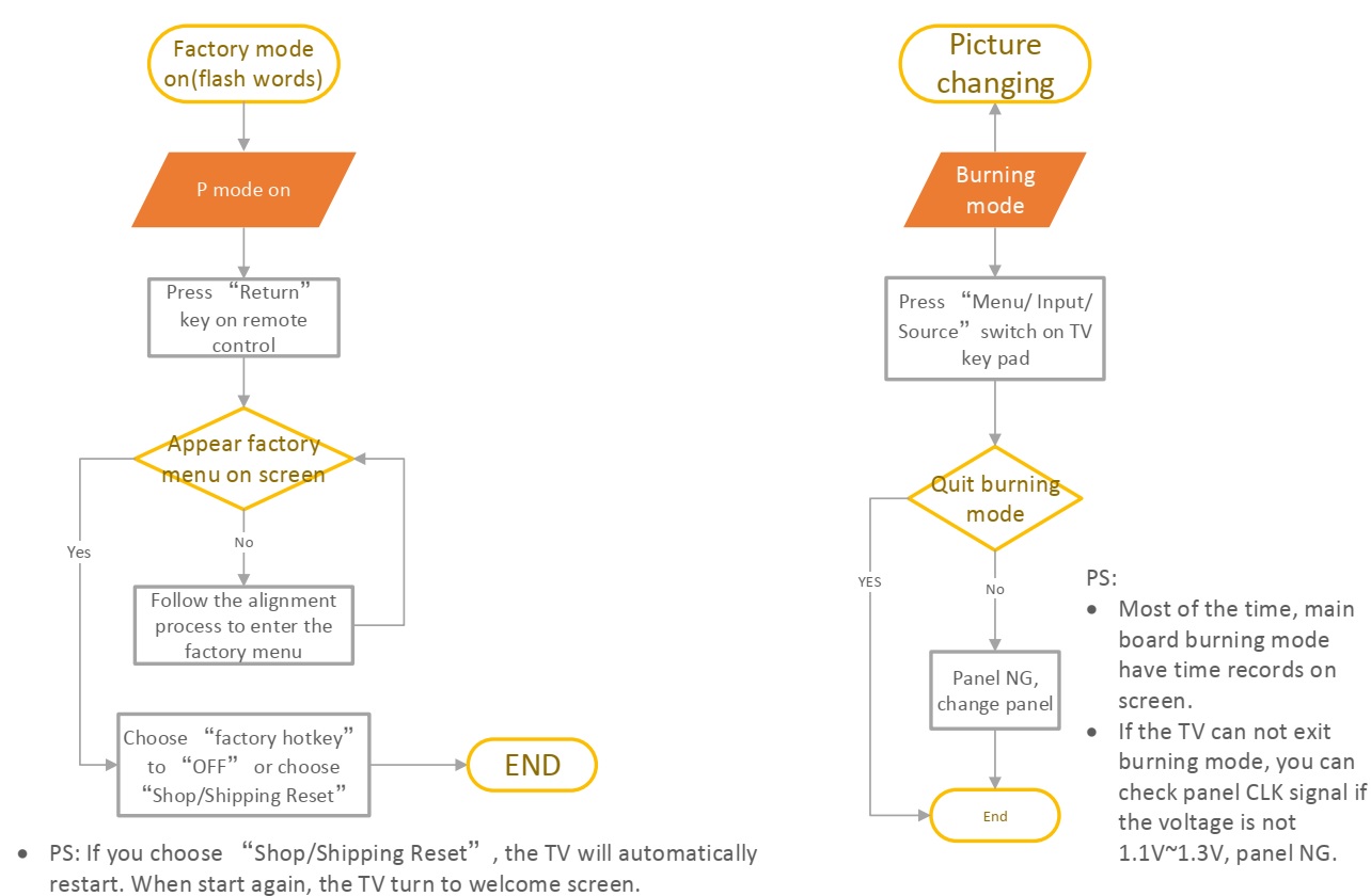
P mode on and burning mode


Tuesday, September 27, 2022

LG OL100 Hi-Fi system - How to download programs, FOTA update step, Micom program, option equalization and demonstration program

 Output power

Total output – 2000 watts RMS

High – 550 Watts RMS * 2 (6 Ohms at 1 KHz, 25% THD)

Low – 900 Watts RMS (12 Ohms at 200 Hz, 15% THD)

Hidden keys

PROGRAM DOWNLOAD

SUB MCS PROGRAM (SUB MCS CHIP)
Download program file name must be SUB_OL100_HAC_YYMMDDX.bin
If security program(Water Wall) is activated on PC, you must save the file to the USB storage device and disable the security software, then download the file to your set.
Downloading file proceeds at USB2 function.
Caution: When downloading the file, you should neither unplug the USB device, change to the other function, nor power off the device. USB device must be unplugged when the downloading process is completed.

MAIN MCS PROGRAM (MAIN MCS CHIP)
Download program file name must be MAIN_OL100_HAC_YYMMDDX.bin
If security program(Water Wall) is activated on PC, you must save the file to the USB storage device and disable the security software, then download the file to your set.
Downloading file proceeds at USB1 function.
Caution: When downloading the file, you should neither unplug the USB device, change to the other function, nor power off the device. USB device must be unplugged when the downloading process is completed.

MICOM PROGRAM
Download program file name must be MICOM_OL100_HAC_YYMMDDX.HEX
If security program(Water Wall) is activated on PC, you must save the file to the USB storage device and disable the security software, then download the file to your set.
Downloading file proceeds at USB2 function.
Caution: When downloading the file, you should neither unplug the USB device, change to the other function, nor power off the device. USB device must be unplugged when the downloading process is completed.

OPTION, EQ & DEMO PROGRAM
Download program file name must be OPTEQ_DEMO_OL100_HAC_XXXX.BIN
If security program(Water Wall) is activated on PC, you must save the file to the USB storage device and disable the security software, then download the file to your set.
Downloading file proceeds at USB1 function.
Caution: When downloading the file, you should neither unplug the USB device, change to the other function, nor power off the device. USB device must be unplugged when the downloading process is completed.

FOTA UPDATE STEP USING BT APP


Sunday, September 25, 2022

Philips 32” LCD TV chassis PL19.00 - ELECTRICAL ADJUSTMENTS - How to enter the service mode, How to initialize, How to renew the firmware, SMPS circuit diagram of Type A,B and C


Proper service and repair is important to the safe, reliable operation of all Funai Equipment. The service procedures recommended by Funai and described here are effective methods of performing service operations. Some of these service special tools should be used when and as recommended.

Service adjustments of Philips (This chassis) PL19.00 and Funai are similar.  Both sets uses the same number main board. SMPS schematics too.

Electrical adjustments are required after replacing circuit components and certain mechanical parts. It is important to perform these adjustments only after all repairs and
replacements have been completed.
Also, do not attempt these adjustments unless the proper equipment is available.

Test Equipment Required
Remote control unit (Philips Smart: RC6 code)
Color Analyzer, CA-310 (KONICA MINOLTA Luminance meter) or measuring instrument as good as CA-310.
How to set up the service mode:
Service mode
1. Turn the power on.
2. Press [
0], [6], [2], [5], [9], [6], and [INFO] buttons on the remote control unit in this order. The following screen appears.

Purity Check Mode
This mode cycles through full-screen displays of red, green, blue, and white to check for non-active pixels.
1. Enter the service mode.
2. Each time the [7] button on the remote control unit is pressed, the display changes as follows.

The White Balance Adjustment should be performed when replacing the LCD Panel, Digital Main CBA.
2. White Balance Adjustment
Purpose:
To mix red and blue beams correctly for pure white.
Symptom of Maladjustment: White becomes bluish or reddish.

1. Operate the unit for more than 30 minutes.
2. Enter the service mode.
3. Press [VOLUME DOWN] button three times on the remote control unit to select “Drive setting” mode. “Drive -” appears in the screen.
4. Set the color analyzer at the CHROMA mode and zero point calibration. Bring the optical receptor pointing at the center of the LCD-Panel.

Note: The optical receptor must be set perpendicularly to the LCD Panel surface.
5. Press [
3] button to select the “HDB” for High Drive Blue adjustment. (“HDB” appears in the screen.)

6. Press [MENU] or [HOME] button. The internal Raster signal appears in the screen. (“Internal (Single)” appears in the upper right of the screen as shown below.)

7. Press [CHANNEL UP/DOWN] buttons to adjust the colour temperature becomes 6500°K (x= 0.3127 ± 4% / y= 0.329 ± 4.5%).
8. Press [
1] button to select the “HDR” for High Drive Red adjustment (“HDR” appears in the screen.) and press [CHANNEL UP/DOWN] buttons to adjust the colour temperature.
9. If necessary, adjust the “HDB”, “HDR” again.
10. Press [
6] button to select the “MDB” for Middle Drive Blue adjustment (“MDB” appears in the screen.) and press [CHANNEL UP/DOWN] buttons to adjust the colour temperature.

11. Press [4] button to select the “MDR” for Middle Drive Red adjustment (“MDR” appears in the screen.) and press [CHANNEL UP/DOWN] buttons to adjust the colour temperature.
12. If necessary, adjust the “MDB” or “MDR” again.
13. Press [
9] button to select the “LDB” for Low Drive Blue adjustment (“LDB” appears in the screen.) and press [CHANNEL UP/DOWN] buttons to adjust the colour temperature.

14. Press [7] button to select the “LDR” for Low Drive Red adjustment (“LDR” appears in the screen.) and press [CHANNEL UP/DOWN] buttons to adjust the color temperature.
15. Press [8] button to select the “LDG” for Low Drive Green adjustment (“LDG” appears in the screen.) and press [CHANNEL UP/DOWN] buttons to adjust the color temperature.
16. If necessary, adjust the “LDB”, “LDR” or “LDG” again.
17. Press [VOLUME DOWN] button to shift to the “Debugging Message” mode.  If there is no message under “[WB]” section, this adjustment completes.  If “Drive settings are NG. Retry again.” Is displayed, repeat above steps from 5. to 16. Then check “Debugging Message” again. If “Drive settings are NG. Retry again.” is displayed;
replace the LCD Panel or Digital Main CBA.
18. To cancel or to exit from the White Balance Adjustment, press [PREV. CH] button.

HOW TO INITIALIZE THE LCD TV
The purpose of initialization is to place the set in a new out of box condition. The customer will be prompted to select a language and program channels after the set has been initialized.
To put the program back at the factory-default, initialize the LCD TV using the following procedure.
Note: Disconnect any device from the USB Port before you conduct on this procedure.
Please use the: Remote Control Unit (Philips Smart)
1. According to above steps, enter into the service mode.
- To cancel the service mode, press [
< ] button on the remote control unit.
2. Press [
Red], [2], [7], [3] buttons to implement forced the initialized.
3. Make sure to confirm the “INITIALIZED FINISH” appears in the green screen.
4. Unplug the AC Cord and plug it back on again.

FIRMWARE RENEWAL MODE
Equipment Required
a. USB storage device
b. Remote Control Unit (ROKU)
Firmware Update Procedure
User Upgrade
(Filename example: update.roku)
Upgrade the firmware only. The setting values will not be initialized.
Update procedure
Please use the: Remote Control Unit (ROKU)
1. Turn the power on.
2. Insert the USB storage device to the USB port as shown below.

3. Reset Roku TV.
4. Press the [Home ] button, Home - Setting - System - Advanced system settings - Factory reset, enter into - Factory reset everything.

Ensure TV must connect the network, press the [Home ] × 5, >  <  > < and [ > ] enter into wifi connect interface.

6. Enter into Roku update interface, press the [Home ] button × 5, [<< ] × 4, and  [>|| ] × 1 enter into Roku update interface.

Select “USB” update.

9. After finished the updating software, TV set will automatically reboot.

SMPS Schematic diagrams for Type A and Type B and Type C


Wednesday, August 24, 2022

Sharp LC32, LC40 and LC43 inch LCD TVs – How to enter the service mode - Software upgrade - Service mode adjustments details - Smart TV troubleshooting and more


Applicable to these models

LC-32CHE5111E, LC-32CHE5111K, LC-32CHE5111KW, LC-32CHE5112E, LC-32CHE5112EW, LC-32CHE6131K, LC-32CHE6132E, LC-32CHF5111K, LC-32CFE6132E, LC-32CHE5221E, LC-32CHE6242E, LC-32CFE6241E, LC-32CFE6241K ,LC-32CFE6242E, LC-32CFE6352E, LC-32CFE6452E, LC-40CFE5111E, LC-40CFE5112E, LC-40CFE5111K, LC-40CFE6132E, LC-40CFE5221E, LC-40CFE5221K, LC-40CFE6241K, LC-40CFE6242E, LC-40CFE6351E, LC-40CFE6351K, LC-40CFE6352E, LC-40CFE6452E, LC-43CFF5111K, LC-43CFF6001K, LC-43CFF6002E, LC-43CFE5111E, LC-43CFE5111K, LC-43CFE5112E, LC-43CFE6131E, LC-43CFE6131K, LC-43CFE6132E, LC-43CFE6141EW, LC-43CFE6142EW, LC-43CFE5222E, LC-43CFE6241K, LC-43CFE6242E, LC-43CFE6252EW, LC-32CFE6351K, LC-43CFE6351E, LC-43CFE6352E, LC-43CFE6352K, LC-43CFE6451K, LC-43SFE7332E, LC-43CFE6452E, LC-43SFE7452E


How to enter the factory menu (Service Mode)

Press the RC buttons in this sequence: “Menu 1 1 4 7” to enter the factory menu.

Description:
ROOT
0 Factory Init All
1 BURNNG MODE
2 ADC ADJUST
3 PICTURE
4 SOUND
5 PANEL
6 DEBUG
7 GENERAL SETTING

8 EMC SETTING
9 INIT CHANNEL
10 SW UPGRADE
11 SW INFORMATION
12 SHIPMENT (KEEP ADC)
13 6M50 SETTING *
14 SII9679 SETTING *
15 VTV1222 SETTING *

Factory menu Homepage

0 Factory Init All
Initialize TV. Restore to factory configures.
1
BURNNG MODE
Aging mode. For test panel. If it’s in operation, use key board “power” to quit.

2 ADC SETTING
It’s for adjusting the YPBPR and PC color. Press key “right” or “ok” to enter the subpage.
ADC Mode: Display current input source and resolution.
ADC Auto Adjust: Start to auto color to get ADC value.
[ADC]R-Gain: Display current ADC R value.
[ADC]R-Offset: Display current ADC R offset value.
[ADC]G-Gain: Display current ADC G value.
[ADC]G-Offset: Display current ADC G offset value.
[ADC]B-Gain: Display current ADC B value.
[ADC]B-Offset: Display current ADC B offset value.

3 PICTURE
SOURCE:
Current input source. (use for change source)
STANDARD SETTING: Standard analog quality setting (Like contrast ...etc) for different Picture mode. It will change OSD picture menu’s standard picture mode setting.
NONLINE CURVE: The nonlinear curve for picture mode. To set OSD quality setting (like contrast. brightness ...etc) the value 0,25,50.75.100 corresponding actual nonline curve value.
W/B ADJUST: Standard white balance setting. Select warm - cold - normal mode and set its RGB value to change OSD picture menu’s white balance standard value. R-Gain increase red colour, G-Gain increase green colour, B-Gain increase blue colour.
Color Setting, Luma Setting, Peaking Setting, NR Setting, CTI Setting, Gamma, DLC, Film Mode, PQ By Pass: Change these setting will change register for PQ.
Suggest do not change these setting.

4 SOUND

SOURCE: Current input source. (use for change source)
SOUND MODE: Standard sound setting (Like EQ treble bass) for different Sound mode .It will change Sound menu’s standard sound mode setting.
EQ: sound in different frequency range value.
VOLUME CURVE: Volume curve. At least ten steps is adjustable. To set sound value from 1 to 100 corresponding actual nonline curve value. It will change current sound actual value. For example, TAB-50 is 925, that’s on the sound OSD page, use key vol+or- to adjust the value to 50, the volume is 925.
VOLUME SETTINGS: setting AVL mode and threshold ...etc. AVD: auto volume control. Vol PreScale DTV... SCART: Set different source’s sound value.
PEQ: Adjust the audio effect by different frequency range. EQ: sound in different frequency range value. PEQ: more frequency range than EQ;

5 PANEL
Backlight:
It’s for adjusting the non-eco and eco backlight.
Depends on which mode is selected in OSD.
LVDS Map ID: Modify this according to your panel. It is the combination of the TI Mode, Color Bits, Swap Port and Output Bit.
LVDS TI Mode: Have VESA or JEICA mode. It’s related to LVDS Map.
LVDS Color Bits: Set lVDS data interface type. (6bit or 8bit or 10bit).
LVDS Swap Port: LVDS A or B Port data swap.
LVDS Output Bit: Set LVDS data output type. (6bit or 8bit or 10bit).
PWM Freq: Modify PWM frequency
PWM Fraq Step: The speed when you modify PWM Freq value.
Mirror: mirror TV. Switch your screen upside down.

6 DEBUG
MStar Fac Menu:
Show MStar Factory Menu.
Uart Enable: To enable serial port with print debug infomation. If you want to got the debug info by the ISP tool, you can set this item to “ON”.
VIF setting: RF non-standard signal test.
Erase MAC: erase Mac address. The password is “
4711”.
Erase HDCP Key: erase HDCP key. Must erase key before upgrade key. The password is “
4711”.
Erase HDCP2.0 Key: erase HDCP2.0 key. Must erase key before upgrade key. The password is “
4711”.
Erase CIplus Key: erase CIplus key. Must erase key before upgrade key. The password is “
4711”.
Erase ADC: Erase ADC value. The password is “4711”.
Erase WB: Erase white balance. The password is “
4711”.
Era&Gen NandBin: Erase All and generate Nandbin (Use for production). The password is “
4711”. It will erase flash. This function is for CVTE test, Suggest do not erase this.
RB-Time: Suggest do not do this. The password is “
4711”.
Format USB device: Format USB, your USB device will be NULL.
Print to USB: debug print information output to USB device. Easy to get print out.
Logo On or Off: have power on logo or not.

7 GENERAL SETTING
Test Pattern:
Display test picture to check panel.
OVERSCAN: It’s for adjusting the over scan of picture.
Timer Test: To speed up the time. Only for QC test.
WDT: Watch dog on or off
Power On Mode: After power on state. It’s for setting power state when power on. There are three option off or on or last. ‘off’ means it’ll enter standby state; ’on’ means it’ll power on directly without standby; ‘last’ means it’ll enter the last state : standby or power on. It decided by the state when you turn off the power.
EN ADC Value: Use for keypad test. Get keypad ADC value.
ADC Value: The ADC value of current press key. Use this need EN ADC Value turn to on.
CI+ Version Switch: Switch CI+ Version both 1.2 and 1.3. It will lead TV restart.
Hotel Mode: Enter Hotel mode setting.
Capture Screen: If set to ON, we can capture screen when press setup key.

8 EMC SETTING
It’s for adjusting some parameters about EMC.
9
INIT CHANNEL
CH Table import:
import channel table from USB, need channel table in USB that export before.
CH Table export: export channel table to USB.
CH Table Init: Initial Channel Table, It will be NULL.

10 Software Upgrade
Upgrade TV:
For upgrade Software. Need UBS device and. bin file.
Bin name: .bin name for upgrade

11 SW INFORMATION
Mantis or OCS:
The model of software.
Main board: The main board of software to use.
Panel Name: The panel of software to use.
AT version: The version of factory auto test.
Build Time: The build time of software. (ID of software)
Operation Time: The time of TV total operation time counter.

12 Shipment (keey ADC WB)
Initialize TV. Restore to factory configures. But keep ADC and WB configure.
Extern:
6M50, SII9679 and VTV1222 setting item is used to boot or upgrade other chips in board. Only for 4K2K board.

SOFTWARE UPGRADE

MSD6308 Upgrade Instruction
6308 including 6308RT, 6308RTE, 6308RTEB and 6308RTEC, you should make sure the main chipset correspond to the upgrade program before upgrading. This manual provides 3 upgrading methods with 6308RT as the example, the three methods are: User menu upgrade, Power on upgrade, TFTP (network) upgrade.

At the beginning of upgrading, if prompt “PWM-REF doesn’t match”, please make sure the new software PWM-REF won’t damage the panel, and then change the file name into AllUpgrade-6308-SOS.bin and power on to upgrade.

User Menu Upgrade
A Operation Procedure
• Turn on the TV set
• Copy the bin file to the root directory of USB device
• Plug the USB device to the USB port
• Select “Software Update (USB)” on the OSD and follow the instructions. TV will switch-off automatically after upgrading finished.
The upgrade process prompts as follows:

B Upgrade Prompt
When upgrading, the TV set will light panel according to the panel parameter, and display the progress bar. If the panel parameter of board matches the panel, you will see the following image:

C Upgrade Flashing Status
You can judge the upgrade progress by flashing of the remote control LED light.
Upgrading
Red 1000ms Green1000ms alternates, the TV set will turn to Upgrade succeed or Upgrade Failed status after the upgrading process.
Main program upgrade succeed
Red 250ms Green 250ms alternates, flashing before power off.
Main program upgrade Failed
Red 1750ms Green 250ms alternates, flashing before power off.
• Notes:
• In the upgrade process, as timer software is used to control flashing, situations such as LED light stuck when creating partition of flash, is normal phenomenon.
6.3 Power On Upgrade
A Operation Procedure
• Power Off the TV set
• Copy AllUpgrade-6308XXX.bin to the root directory of your USB memory stick
• Plug the USB device to the USB port
• Power on the TV, if the upgrade file name matches the main chipset, the LED light will flashing and the upgrade process starting. The TV set won’t auto reboot after finishing the upgrade process, customer should pull the USB out and power off the TV set manually.

TFTP (network) Upgrade
A Upgrade Tools

C Upgrade Process
• Connect serial port tools
• Connect the PC and main board with network cable, connect the serial port. Set the cable adapter IP as 192.168.1.100.

Connect the serial port, enter the following command to set main board and tftp server IP. setenv ipaddr 192.168.1.101 setenv serverip 192.168.1.100 saveenves

Notes:
Direct Connect network cable between PC and MB To Upgrade is available in the version higher than svn5215.
• Run the tftpd32.exe in your upgrading folder.

After setting IP, enter the following command to upgrade the corresponding program.
Upgrade Mboot: mstar upgrade-mboot.txt
Reboot: reset
Re-enter command to set IP.
Upgrade main program: mstar mscript/auto-update.txt
Notes:
auto-update.txt will clear factory burning parameter of KEY/MAC, please use it cautiously.
upgrade-mboot.txt and auto-update.txt are text files, engineer can refer to the two text files when entering corresponding upgrade command.

PICTURE ADJUSTMENT

White Balance
• Change source to HDMI
• Load 80% White pattern from signal generator
• Enter Factory Menu by pressing MENU + 1147
• Choose 3 Picture
• Choose 3 W/B Adjust
• In 0 WB Mode choose Warm or Normal or Cold
• Change R-Gain or G-Gain or B-Grain to meet specification

HOTEL MODE

To enter Hotel mode you need press buttons on RC in following sequence: MENU 7 9 0 6.
Structure of Hotel menu:
1. Hotel Mode – on or off hotel mode
2. Source Lock – you can lock any source
3. Default Source – source which appears after turn on TV
4. Default Prog – channel which appears after turn on TV
5. DTV channel type – type of channel which appears after turn on TV
6. Default volume – volume which will be set itself after turn on TV
7. Max volume – maximum volume which can be set
8. CH Table Import – import all channels and settings from USB
9. CH Table Export – export all channels and setting to USB
10. Clear Lock – reset all hotel mode settings.

SMART TV TROUBLESHOOTING

TV cant connect to wi-fi network.
Steps to fix this issue:
• Set on your wi-fi router/access point WPA or WPA2 encryption. WEP is not supported.
• Set on your wi-fi router DNS to
8.8.8.8 (Google DNS server)
• If above does not help, try to upgrade software again.
2. Entering AQUOS NET+ is not possible
• Most probable cause may be missing or wrong MAC address.
Steps of test validity of MAC address:
1. Press
MENU + 1147 to enter factory menu
2. Go to 11 SW Information and press OK (Pic.1)
3. Check item 10 Sraf Valid MAC
4. If there is (OK), it means everything is ok (Pic. 2)
Note: It may take few seconds until “OK” shows after turning TV on.
5. If there is (NG), means either MAC address is missing or is not supported by current SDK (Pic.3).
In case of NG test result:
1. Check 7 Mac Addr
2. If value is FF:FF:FF:FF:FF:FF – this means MAC was not added during production of mainboard.
Solution to fix this issue: Request new MAC addresses from TV manufacturer.
3. If value is different than FF:FF:FF:FF:FF:FF – Means current address is not supported by software.
Solution to fix this issue: Upgrade TV software to the latest version.


Monday, August 15, 2022

LG LED TV 32LK610BPUA, 32LK610BBUA Smart JIG Power Diagnosis Muitl Gender SMPS (Power board) fault diagnosis method


Power Board Muitl Gender JIG Diagram (PN: RAD33187801)


Power Board Muitl Gender JIG Diagnostic model List

Existing 12Y, 13Y, 14Y, 15Y LED models included
15Y, 16Y, 17Y - 18Y OLED, 16 -17 -18 Y LED model Power diagnosis function newly added

15Y -16Y -17Y -18Y OLED Model, 16Y -17Y - 18Y LED Model

Power Board Muitl Gender How to Connect

Power Board Muitl Gender JIG


Power BD Smart Jig Voltage Switch

24V >
20V >

24V
20V

13.2V or 18V  > 24V


Smart Jig Voltage Setting

Note on setup
(The correct power diagnosis can be made only if it is set correctly.)
24V Power Board : Change the switch to 24V of Smart Jig Voltage
20V Power Board : Change the switch to 24V of Smart Jig Voltage

13.2V or 18V Power Board : Change the switch to 24V of Smart Jig Voltage.

15Y OLED (EG96,EF95,EG92,EG93,EG94) Power Board Diagnostic method (1)

Check power board voltage

* Switch the product SW in JIG to LCD.
LCD MODEL Check the power voltage and switch (24V) to the correct voltage.
Fix the LCD MODEL switch to 24V.(Smart JIG)

Disconnect the Main Board 24Pin Power Cable connector.

Connect the 24Pin Power Cable connector to the Muitl Gender JIG 24Pin connector

Power Board Diagnostic method (2)

When the OK LED (24V,12V) turns on, Power Board is normal.
When the NG LED turns on, the Power Board can be judged as defective.

16Y OLED (B6) Power Board Diagnostic method

Connect the 24Pin Power Cable connector to the Multi gender JIG 24Pin connector.

Switch the LCD MODEL S/W to 24V by checking the power voltage.
Fix the LCD MODEL switch to 24V.(Smart JIG)

When the OK LED (24V,12V) turns on, Power Board is normal.
When the NG LED turns on, the Power Board can be judged as defective.

16Y OLED (C6) Power Board Diagnostic method

Check power board voltage.
Smart JIG: Fix the LCD MODEL switch to 24V.(Smart JIG)

Disconnect the Main Board 24Pin Power Cable connector.

Connect the 24Pin Power Cable connector to the Muitl Gender JIG 24Pin connector

When the OK LED (24V,12V) turns on, Power Board is normal.

16Y OLED (E6) Power Board Diagnostic method

Check power board voltage.
Fix the LCD MODEL switch to 24V. (Smart JIG)

Disconnect the Main Board 24Pin Power Cable connector.

Connect the 24Pin Power Cable connector to the Muitl Gender JIG 24Pin connector

When the OK LED (24V,12V) turns on, Power Board is normal.
When the NG LED turns on, the Power Board can be judged as defective.

16Y OLED (G6) Power Board Diagnostic method

Check power board voltage.
Fix the LCD MODEL switch to 24V.(Smart JIG)

Disconnect the Main Board 24Pin Power Cable connector.

Connect the 24Pin Power Cable connector to the Muitl Gender JIG 24Pin connector

When the OK LED (24V,12V) turns on, Power Board is normal.

When the NG LED turns on, the Power Board can be judged as defective.

17Y OLED (B7-C7-E7-G7) Power Board Diagnostic method

Disconnect the Main Board 28Pin Power Cable connector.

Connect the 28Pin Power Cable connector to the Muitl Gender JIG 28Pin connector.

Switch the LCD MODEL SW to 20V by checking the power voltage.
Fix the LCD MODEL switch to 20V.(Smart JIG)

When the OK LED (24V,12V) turns on, Power Board is normal.
When the NG LED turns on, the Power Board can be judged as defective

17Y OLED (W7) Power Board Diagnostic method

Disconnect the Main Board 24Pin Power Cable connector.

Connect the 24Pin Power Cable connector to the Muitl Gender JIG 28Pin connector

Switch the LCD MODEL SW to 20V by checking the power voltage.
Fix the LCD MODEL switch to 20V.(Smart JIG)

When the OK LED (24V,12V) turns on, Power Board is normal.
When the NG LED turns on, the Power Board can be judged as defective.