Test Points
As most signals are digital, it will be difficult to measure waveforms with a standard oscilloscope. However, several key ICs are capable of generating test patterns, which can be controlled via ComPair. In this way it is possible to determine which part is defective.
Perform measurements under the following conditions:
• Service Default Mode.
• Video: Colour bar signal.
• Audio: 3 kHz left, 1 kHz right.
Service Modes
Service Default mode (SDM) and Service Alignment Mode (SAM) offers several features for the service technician, while the Customer Service Mode (CSM) is used for communication between the call centre and the customer.
This chassis also offers the option of using ComPair, a hardware interface between a computer and the TV chassis. It offers the abilities of structured troubleshooting, error code reading, and software version read-out for all chassis.
Note: For the new model range, a new remote control (RC) is used with some renamed buttons. This has an impact on the activation of the Service modes. For instance the old “MENU” button is now called “HOME” (or is indicated by a “house” icon).
Service
Default Mode (SDM)
Purpose
• To create a pre-defined setting, to get the same measurement results as given in this manual.
• To override software protections detected by stand-by processor and make the TV start up to the step just before protection (a sort of automatic stepwise start-up• To start the blinking LED procedure where only LAYER 2 errors are displayed.
SDM default settings
Region Freq. (MHz) Default system
Europe, AP(PAL/Multi) 475.25 PAL B/G
Europe, AP DVB-T 546.00 PID Video: 0B
06 PID PCR: 0B 06 PID
Audio: 0B 07 DVB-T
• All picture settings at 50% (brightness, colour, contrast).
• Sound volume at 25%.
• All service-unfriendly modes (if present) are disabled, like:
– (Sleep) timer.
– Child/parental lock.
– Picture mute (blue mute or black mute).
– Automatic volume levelling (AVL).
– Skip/blank of non-favourite pre-sets
How
to Activate SDM
For this chassis there are two kinds of SDM: an analogue SDM and a digital SDM.
For this chassis there are two kinds of SDM: an analogue SDM and a digital SDM.
•
Analogue SDM: use the standard RC-transmitter and key in the code “062596”,
directly followed by the “MENU” (or “HOME”) button.
Note: It is possible that, together with the SDM, the main menu will appear. To switch it “off”, push the “MENU” (or "HOME") button again.
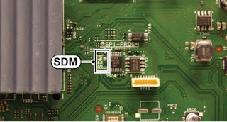
Analogue SDM can also be activated by grounding for a moment the solder path on the SSB, with the indication “SDM”.
• Digital SDM: use the standard RC-transmitter and key in the code “062593”, directly followed by the “MENU” (or "HOME") button.
Note: It is possible that, together with the SDM, the main menu will appear. To switch it “off”, push the “MENU” (or "HOME") button again.
Note: It is possible that, together with the SDM, the main menu will appear. To switch it “off”, push the “MENU” (or "HOME") button again.
Analogue SDM can also be activated by grounding for a moment the solder path on the SSB, with the indication “SDM”.
• Digital SDM: use the standard RC-transmitter and key in the code “062593”, directly followed by the “MENU” (or "HOME") button.
Note: It is possible that, together with the SDM, the main menu will appear. To switch it “off”, push the “MENU” (or "HOME") button again.

After activating this mode, “SDM” will appear in the upper right corner of the screen (when a picture is available).
How to Navigate
When the “MENU” (or “HOME”) button is pressed on the RC transmitter, the TV set will toggle between the SDM and the normal user menu.
How to Exit SDM
Use one of the following methods:
• Switch the set to STAND-BY via the RC-transmitter.
• Via a standard customer RC-transmitter: key in “00”- sequence.
Service Alignment Mode (SAM)
Purpose
• To perform (software) alignments.
• To change option settings.
• To easily identify the used software version.
• To view operation hours.
• To display (or clear) the error code buffer.
How to Activate SAM
Via a standard RC transmitter: Key in the code “062596” directly followed by the “INFO” or “OK” button. After activating SAM with this method a service warning will appear on the screen, continue by pressing the “OK” button on the RC.
Contents
of SAM
• Hardware Info.
• Hardware Info.
–
A. SW Version. Displays the software version of the main software (example:
Q555X-1.2.3.4 = AAAAB_X.Y.W.Z).
• AAAA= the chassis name.
• B= the software branch version. This is a sequential number (this is no longer the region indication, as the software is now multi-region).
• X.Y.W.Z= the software version, where X is the main version number (different numbers are not compatible with one another) and Y.W.Z is the sub version number (a higher number is always compatible with a lower number).
– B. STBY PROC Version. Displays the software version of the stand-by processor.
– C. Production Code. Displays the production code of the TV, this is the serial number as printed on the back of the TV set. Note that if an NVM is replaced or is initialized after corruption, this production code has to be re-written to NVM. ComPair will foresee in a possibility to do this.
• Operation Hours. Displays the accumulated total of operation hours (not the stand-by hours). Every time the TV is switched “on/off”, 0.5 hours is added to this number.
• Errors (followed by maximum 10 errors). The most recent error is displayed at the upper left,
• Reset Error Buffer. When “cursor right” (or “OK” button) pressed here, followed by the “OK” button, the error buffer is reset.
• Alignments. This will activate the “ALIGNMENTS” sub menu.
• Dealer Options. Extra features for the dealers.
• Options. Extra features for Service. For more info regarding option codes.
Note that if the option code numbers are changed, these have to be confirmed with pressing the “OK” button before the options are stored, otherwise changes will be lost.
• Initialize NVM. The moment the processor recognizes a corrupted NVM, the “initialize NVM” line will be highlighted. Now, two things can be done (dependent of the service instructions at that moment):
– Save the content of the NVM via ComPair for development analysis, before initializing. This will give the Service department an extra possibility for diagnosis (e.g. when Development asks for this).
– Initialize the NVM
Note:
When the NVM is corrupted, or replaced, there is a high possibility that no
picture appears because the display code is not correct. So, before initializing
the NVM via the SAM, a picture is necessary and therefore the correct display
option has to be entered. To adapt this option, it’s advised to use ComPair or
a method via a standard RC (described below).
Changing the display option via a standard RC: Key in the code “062598” directly followed by the “MENU” (or "HOME") button and “XXX” (where XXX is the 3 digit decimal display code as mentioned on the sticker in the set). Make sure to key in all three digits, also the leading zero’s. If the above action is successful, the front LED will go out as an indication that the RC sequence was correct. After the display option is changed in the NVM, the TV will go to the Stand-by mode. If the NVM was corrupted or empty before this action, it will be initialized first (loaded with default values). This initializing can take up to 20 seconds.
Changing the display option via a standard RC: Key in the code “062598” directly followed by the “MENU” (or "HOME") button and “XXX” (where XXX is the 3 digit decimal display code as mentioned on the sticker in the set). Make sure to key in all three digits, also the leading zero’s. If the above action is successful, the front LED will go out as an indication that the RC sequence was correct. After the display option is changed in the NVM, the TV will go to the Stand-by mode. If the NVM was corrupted or empty before this action, it will be initialized first (loaded with default values). This initializing can take up to 20 seconds.
Location
of Display Option Code sticker

• Store - go right. All options and alignments are stored when pressing “cursor right” (or the “OK” button) and then the “OK”-button.
• Operation hours display. Displays the accumulated total of operation hours of the screen itself. In case of a display replacement, reset to “0” or to the consumed operation hours of the spare display.
• SW Maintenance.
– SW Events. In case of specific software problems, the development department can ask for this info.
– HW Events. In case of specific software problems, the development department can ask for this info :
- Event 26: refers to a power dip, this is logged after the TV set reboots due to a power dip.
- Event 17: refers to the power OK status, sensed even before the 3 x retry to generate the error code.
• Test settings. For development purposes only.
• Development file versions. Not useful for Service purposes, this information is only used by the development department.
• Upload to USB. To upload several settings from the TV to an USB stick, which is connected to the SSB. The items are “Channel list”, “Personal settings”, “Option codes”, “Alignments”, “Identification data” (includes the set type and prod code + all 12NC like SSB, display, boards), “History list”. The “All” item supports to upload all several items at once.
First a directory “repair\” has to be created in the root of the USB stick.
To upload the settings, select each item separately, press “cursor right” (or the “OK” button), confirm with “OK” and wait until the message “Done” appears. In case the download to the USB stick was not successful, “Failure” will be displayed. In this case, check if the USB stick is connected properly and if the directory “repair” is present in the root of the USB stick. Now the settings are stored onto the USB stick and can be used to download into another TV
or other SSB. Uploading is of course only possible if the software is running and preferably a picture is available.
This method is created to be able to save the customer’s TV settings and to store them into another SSB.
• Download from USB. To download several settings from the USB stick to the TV, same way of working needs to be followed as described in “Upload to USB”. To make sure that the download of the channel list from USB to the TV is executed properly, it is necessary to restart the TV and tune to a valid preset if necessary. The “All” item supports to download all several items at once.
•
NVM editor. For NET TV the set “type number” must be entered correctly.
Also the production code (AG code) can be entered here via the RC-transmitter.
Correct data can be found on the side/rear sticker.
Also the production code (AG code) can be entered here via the RC-transmitter.
Correct data can be found on the side/rear sticker.
How
to Navigate
• In SAM, the menu items can be selected with the “CURSOR UP/DOWN” key on the RC-transmitter. The selected item will be highlighted. When not all menu items fit on the screen, move the “CURSOR UP/DOWN” key to display the next/previous menu items.
• With the “CURSOR LEFT/RIGHT” keys, it is possible to:
– (De) activate the selected menu item.
– (De) activate the selected sub menu.
• With the “OK” key, it is possible to activate the selected action.
How to Exit SAM
Use one of the following methods:
• Switch the TV set to STAND-BY via the RC-transmitter.
• Via a standard RC-transmitter, key in “00” sequence, or select the “BACK” key.
Customer Service Mode (CSM)
Purpose
When a customer is having problems with his TV-set, he can call his dealer or the Customer Helpdesk. The service technician can then ask the customer to activate the CSM, in order to identify the status of the set. Now, the service technician can judge the severity of the complaint. In many cases, he can advise the customer how to solve the problem, or he can decide if it is necessary to visit the customer. The CSM is a read only mode; therefore, modifications in this mode are not possible.
When in this chassis CSM is activated, a test pattern will be displayed during 5 seconds (1 second Blue, 1 second Green and 1 second Red, then again 1 second Blue and 1 second Green). This test pattern is generated by the PNX51X0 (located on the 200Hz board as part of the display). So if this test pattern is shown, it could be determined that the back end video chain (PNX51X0 and display) is working. For TV sets without the PNX51X0 inside, every menu from CSM will be used as check for the back end chain video.
When CSM is activated and there is a USB stick connected to the TV set, the software will dump the CSM content to the USB stick. The file (CSM_model number_serial number.txt) will be saved in the root of the USB stick. This info can be handy if no information is displayed.
When
in CSM mode (and a USB stick connected), pressing “OK” will create an extended
CSM dump file on the USB stick. This file (Extended_CSM_model number_serial
number.txt) contains:
• The normal CSM dump information,
• All items (from SAM “load to USB”, but in readable format),
• Operating hours,
• Error codes,
• Software/Hardware event logs.
To have fast feedback from the field, a flashdump can be requested by development. When in CSM, push the “red” button and key in serial digits ‘2679’ (same keys to form the word ‘COPY’ with a cellphone). A file “Dump_model number_serial number.bin” will be written on the connected USB device. This can take 1/2 minute, depending on the quantity of data that needs to be dumped.
Also when CSM is activated, the LAYER 1 error is displayed via blinking LED. Only the latest error is displayed.
How
to Activate CSM
Key in the code “123654” via the standard RC transmitter.
Note: Activation of the CSM is only possible if there is no (user) menu on the screen.
Key in the code “123654” via the standard RC transmitter.
Note: Activation of the CSM is only possible if there is no (user) menu on the screen.
How
to Navigate
By means of the “CURSOR-DOWN/UP” knob on the RC transmitter, can be navigated through the menus.
Contents of CSM
The contents are reduced to 3 pages: General, Software versions and Quality items. The group names itself are not shown anywhere in the CSM menu.
General
• Set Type. This information is very helpful for a helpdesk/workshop as reference for further diagnosis. In this way, it is not necessary for the customer to look at the rear of the TV-set. Note that if an NVM is replaced or is initialized after corruption, this set type has to be re-written to NVM. ComPair will foresee in a possibility to do this. The update can also be done via the NVM editor available in SAM. • Production Code. Displays the production code (the serial number) of the TV. Note that if an NVM is replaced or is initialized after corruption, this production code has to be re-written to NVM. ComPair will foresee in a possibility to do this. The update can also be done via the NVM editor available in SAM.
•
Installed date. Indicates the date of the first installation of the TV. This
date is acquired via time extraction.
• Options 1. Gives the option codes of option group 1 as set in SAM (Service Alignment Mode).
• Options 2. Gives the option codes of option group 2 as set in SAM (Service Alignment Mode).
• 12NC SSB. Gives an identification of the SSB as stored in NVM. Note that if an NVM is replaced or is initialized after corruption, this identification number has to be re-written to NVM. ComPair will foresee in a possibility to do this. This identification number is the 12nc number of the SSB.
• 12NC display. Shows the 12NC of the display.
• 12NC supply. Shows the 12NC of the power supply.
• 12NC 200Hz board. Shows the 12NC of the 200Hz Panel (when present).
• 12NC AV PIP. Shows the 12NC of the AV PIP board (when present)
Software
versions
• Current main SW. Displays the build-in main software version. In case of field problems related to software, software can be upgraded. As this software is consumer upgradeable, it will also be published on the Internet.
Example: Q55xx1.2.3.4
• Stand-by SW. Displays the build-in stand-by processor software version. Upgrading this software will be possible via ComPair or via USB
Example: STDBY_83.84.0.0.
• e-UM version. Displays the electronic user manual software-version (12NC version number). Most significant number here is the last digit.
• FPGA software.
Quality items
• Signal quality. Bad / average /good (not for DVB-S).
• Ethernet MAC address. Displays the MAC address present in the SSB.
• Wireless MAC address. Displays the wireless MAC address to support the Wi-Fi functionality.
• BDS key. Indicates if the set is in the BDS status.
• CI module. Displays status if the common interface module is detected.
• CI + protected service. Yes/No.
• Event counter :
S : 000X 0000(number of software recoveries : SW
EVENT-LOG #(reboots)
S : 0000 000X (number of software events : SW EVENTLOG #(events)
H : 000X 0000(number of hardware errors)
H : 0000 000X (number of hardware events : SW EVENTLOG #(events).
How to Exit CSM
Press “MENU” (or "HOME") / “Back” key on the RC-transmitter.
Stepwise Start-up
When the TV is in a protection state due to an error detected by stand-by software (error blinking is displayed) and SDM is activated via shortcutting the SDM solder path on the SSB, the TV starts up until it reaches the situation just before protection.
So, this is a kind of automatic stepwise start-up. In combination with the start-up diagrams below, you can see which supplies are present at a certain moment. Caution: in case the start-up in this mode with a faulty FET 7U0X (diagram B02A) is done, you can destroy all IC’s supplied by the +1V8 and +1V1, due to overvoltage (12V on XVX-line). It is recommended to measure first the FET 7U0X or others FET’s on short-circuit before activating SDM via the service pads.

The
abbreviations “SP” and “MP” in the figures stand for:
• SP: protection or error detected by the Stand-by Processor.
• MP: protection or error detected by the MIPS Main Processor.
• SP: protection or error detected by the Stand-by Processor.
• MP: protection or error detected by the MIPS Main Processor.
