JVC AV20F703 color television service mode, adjustments, schematic
[Use one among the following instructions to enter the service mode to JVC TVs]
Press the muting key and the recall key of the remote control unit at the same time to display the service menu. To exit the service menu, turn off the power.
OR
In the condition of NO indication
on the screen.
Press the VOL. DOWN button on the set and the Channel button (9) on the remote
control for more than 1 second to appear the adjustment mode on the screen.
Use the Channel UP/DOWN button or Channel button (0-9) on the remote control to select the options.
Press the MENU button on the remote control to end the adjustments.
Basic
adjustments
Constant
voltage
Set condition is AV MODE without signal.
Connect the digital voltmeter to the TP002.
Adjust the VR502 until the DC voltage is 116 +/-1V.
RF AGC
Place the set with Aging Test for
more than 15 minutes.
Receive the VHF HIGH (63dB).
Connect the digital voltmeter between the pin 5 of CP101 and the pin 1 (GND) of
CP101.
Activate the adjustment mode display and
press the channel button (02) on the remote control to select “RF AGC”.
Press the VOL. UP/DOWN button on the remote control until the digital voltmeter
is 2.1 +/- 05V
Cut
off
Adjust the unit to the following
settings.
G. DRIVE=64, B. DRIVE=64, R. BIAS=64, G. BIAS=64, B. BIAS=64
Place the set with Aging Test for more than 15 minutes.
Activate the adjustment mode display and
press the channel button (01) on the remote control to select “CUT OFF”.
Adjust the Screen Volume until a dim raster is obtained.
White
balance. [Adjust after performing cut
off adjustment.]
Place the set with Aging Test for
more than 10 minutes.
Receive the gray scale pattern from the Pattern Generator. Using the remote
control, set the brightness and contrast to normal position.
Activate the adjustment mode display and
press the channel button (13) on the remote control to select “R. BIAS”.
Press the CH. UP/DOWN button on the remote control to select the “R. BIAS”, “G.
BIAS”, “B. BIAS”, “B. DRIVE” or “G. DRIVE”.
Adjust the VOL. UP/DOWN button on the remote control to whiten the R. BIAS, G.
BIAS, B. BIAS, B. DRIVE, and G. DRIVE at each step tone sections equally.
Perform the above adjustments 5 and 6 until the white color is looked like a
white.
Focus
Receive the monoscope pattern.
Turn the Focus Volume fully counterclockwise once.
Adjust the Focus Volume until picture is distinct.
Horizontal
position
Receive the monoscope pattern.
Using the remote control, set the brightness and contrast to normal position.
Activate the adjustment mode display and press the channel button (04) on the
remote control to select “H. POSI”.
Press the VOL. UP/DOWN button on the remote control until the SHIFT quantity of
the OVER SCAN on right and left becomes minimum.
Vertical
position
Receive the monoscope pattern.
Using the remote control, set the brightness and contrast to normal position.
Activate the adjustment mode display and press the channel button (05) on the
remote control to select “V. POSI”.
Press the VOL. UP/DOWN button on the remote control until the horizontal line
becomes fit to the notch of the shadow mask.

Vertical
size
Receive the monoscope pattern.
Using the remote control, set the brightness and contrast to normal position.
Activate the adjustment mode display and press the channel button (07) on the
remote control to select “V. SIZE”.
Press the VOL. UP/DOWN button on the remote control until the SHIFT quantity of
the OVER SCAN on upside and downside becomes 9 +/- 2%.
Vertical linearity [Adjust after performing adjustments in section 2-8. After the adjustment of Vertical Linearity, reconfirm the Vertical Position and Vertical Size adjustments.]
Receive the monoscope pattern.
Using the remote control, set the brightness and contrast to normal position.
Activate the adjustment mode display and
press the channel button (09) on the remote control to select “V. LIN”.
Press the VOL. UP/DOWN button on the remote control until the SHIFT quantity of
the OVER SCAN on upside and downside becomes minimum.
Level
Receive the monoscope pattern
(70dB).
Connect the AC voltmeter to pin 6 of CP101 and the pin 1 (GND) of CP101.
Activate the adjustment mode display and
press the channel button (36) on the remote control to select “LEVEL”.
Press the VOL. UP/DOWN button on the remote control until the AC voltmeter is
75 +/-2mV.
Sub
brightness
Activate the adjustment mode
display and press the channel button
(16) on the remote control to select “BRI. CENT”.
Press the VOL. UP/DOWN button on the remote control until the brightness step
No. becomes “50”.
Receive a broadcast and check if the picture is normal.
Press the INPUT button on the remote control to set to the AV mode. Then
perform the above adjustments 1~3.
Press the INPUT button on the remote control to set to the CS mode. Then
perform the above adjustments 1~3
TINT/color
cent
Receive the color bar pattern.
(RF Input)
Connect the oscilloscope to TP806.
Using the remote control, set the brightness, contrast, color and tint to
normal position.
Activate the adjustment mode display and press the channel button (26) on the
remote control to select “TINT”.
Press the VOL. UP/DOWN button on the remote control until the section “A”
becomes a straight line
Connect the oscilloscope to TP804.
Press the channel button (24) on the remote control to select “COL. CENT”.
Adjust the VOLTS RANGE VARIABLE knob of the oscilloscope until the range
between white 100% and 0% is set to 4.4 scales on the screen of the
oscilloscope.
Press the VOL. UP/DOWN button on the remote control until the red color level
is adjusted to 115 +/-10% of the
white level.
Receive the color bar pattern. (Audio Video Input)
Press the INPUT button on the remote control to set to the AV mode. Then
perform the above adjustments 2~9.
Press the INPUT button on the remote control to set to the CS mode.
Activate the adjustment mode display and press the channel button (26) on the
remote control to select “TINT”.
Press the VOL. UP/DOWN button on the remote control until the tint step No. becomes
“50”.
Press the channel button (24) on the remote control to select “COL. CENT”.
Press the VOL. UP/DOWN button on the remote control until the color step No.
becomes “62”.
Receive a broadcast and check if the picture is normal.

Contrast
max manual
Activate the adjustment mode
display of and press the channel button (18) on the remote control to select
“CONT. MAX”.
Press the VOL. UP/DOWN button on the remote control until the contrast step No.
becomes “85”.
Receive a broadcast and check if the picture is normal.
Press the INPUT button on the remote control to set to the AV mode. Then
perform the above adjustments 1~3.
Press the INPUT button on the remote control to set to the CS mode. Then
perform the above adjustments 1~3.
OSD horizontal
Activate the adjustment mode
display.
Press the VOL. UP/DOWN button on the remote control until the difference of A
and B becomes minimum.
Confirmation
of Fixed Value (step No.)
Check if the fixed values of the each adjustment items are set correctly referring below.

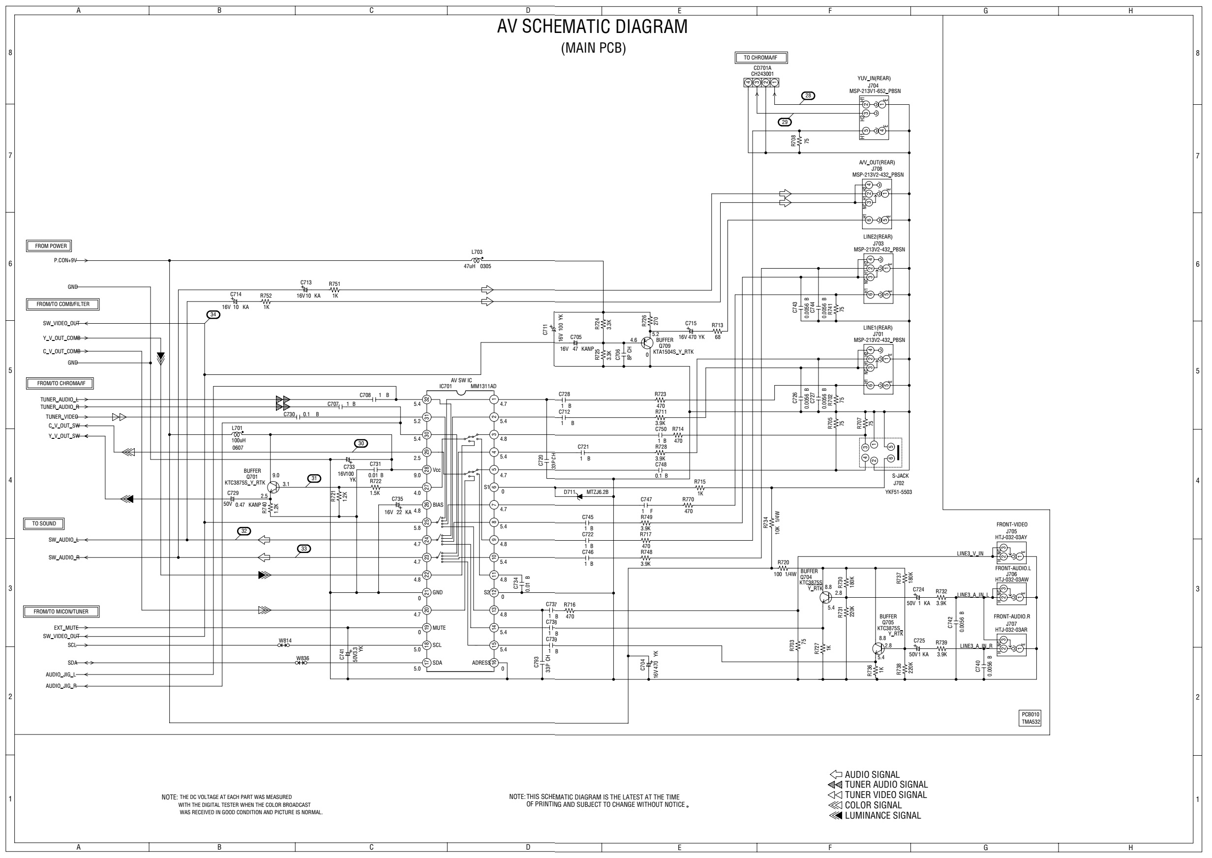
JVC AV20F703
SCHEMATIC MAIN

SCHEMATIC
CHROMA

SCHEMATIC
SMPS

SCHEMATIC-DEFLECTION

Schematic-audio

No comments:
Post a Comment