Pioneer AV Receiver VSX-1130-K, VSX-930-K, VSX-930-S, VSX-90 – using STR2A153 as
SMPS control
Paste a square of acetate
tape 10 × 10 mm in size onto the upper left corner of the AXX7293 shield.
Be careful NOT to conceal the MAC address printed on the shield with the
acetate tape.
Be sure to
paste on the acetate tape after module replacement. (Only for the European models)


Cable dressing

Contrast of PCB
assemblies

PCB locations

Confirmation of the network module
Procedures:
Check
if the set SSID of this unit is displayed on a device such as a PC or a smart
phone, following the procedures shown below.
If the SSID is displayed on the device, the antenna connections of the Network
module are normal.
If the SSID is not displayed, check the antenna cable connections on the
network module.
1 Press "Home Menu" button on a remote control and select
"Network Connection" from the Network, Bluetooth menu on screen.
2 Select "Wireless
Direct" from the Network Connection menu.
3 Select the encryption method to "None" from Security Protocol.
4 Select "Frequency Band" at DN and select the frequency to
"2.4GHz".
5 Select "OK" then press ENTER. "Setting change?" window is
displayed, then select "YES" and press ENTER.
6 Select the SSID shown
on the screen of this receiver.
(e.g. WirelessDirectX: XXXXXX)

How to Check on a PC Equipped with a Wireless LAN Device
Windows 7
1 Left-click on the
wireless network icon on the system tray.
2 Check that the
above-mentioned SSID
(WirelessDirectX:XXXXXX) is displayed on the list that appears.
How to Check on a Smartphone (Example: iPod Touch)
1 At the top screen of
an iPod Touch, select Settings.
2 Select Wi-Fi.
3 Check that the
above-mentioned SSID
(WirelessDirectX:XXXXXX) is displayed in the "Choose a Network" box.

Error Indications When an Abnormality in The Amplifier System is detected
and How to Enter Release Mode
During Standby mode,
simultaneously press and hold the "TUNE ↓" and
"MULTI-ZONE ON/OFF" keys for 5 seconds.

Service mode: How to enter?
During Standby mode, simultaneously
press and hold “MULTI-ZONE ON/OFF” and “ENTER” keys for 5 seconds to enter this
mode. Turn off the power to this unit by setting the main volume level to
“---dB” and Multi-zone to “OFF”.
How to exit
Turning
off the power or pressing the RETURN key returns to the normal mode.


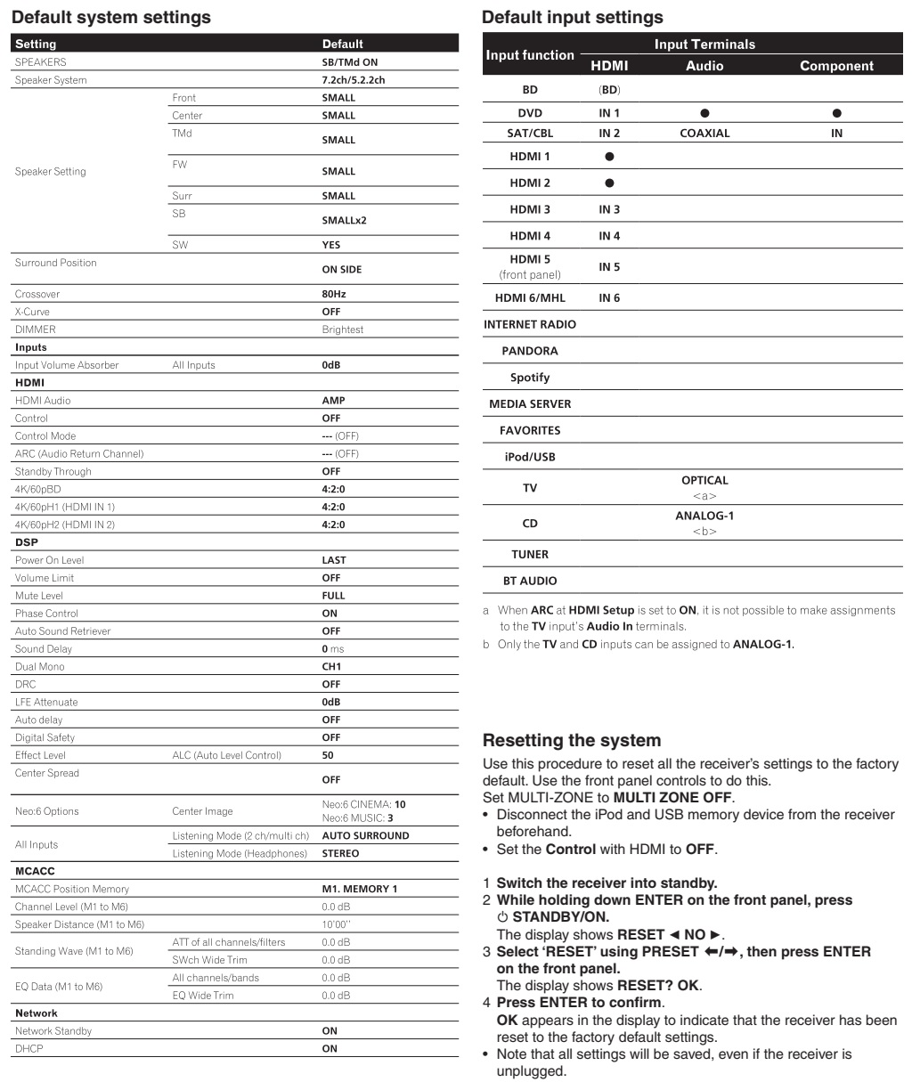
How to reset the system
Resetting the system to the factory default settings
Use
this procedure to reset all the receiver’s settings to the factory default. Use
the front panel controls to do this.
Set MULTI-ZONE to MULTI ZONE OFF.
• Disconnect the iPod and USB memory device from the receiver beforehand.
• Set the Control with HDMI to OFF.
1 Switch the receiver into standby.
2 While holding down ENTER on
the front panel, press STANDBY/ON.
The display shows RESET <NO>..
3 Select ‘RESET’ using PRESET ç / è then press ENTER on the front panel.
The
display shows RESET? OK.
4 Press ENTER to confirm.
OK appears in the display to
indicate that the receiver has been reset to the factory default settings.
• Note that all settings will be saved, even if the receiver is unplugged.
Dressing the antenna
cables

Setting and adjustment
If the adjustment is
shifted or if it becomes necessary to readjust because of part replacement,
etc., perform the adjustment as described below.
• Any value changed in Adjustment mode will be stored in memory as soon as it
is changed. Before readjustment, take note of the original values for reference
in case you need to restore the original settings.
• Use a stable AC power supply.
Adjustment required when the unit is repaired or replaced

USB backup and Updating the Firmware
USB backup
This model is capable of
saving the set values stored in the MAIN Ucom of DMAIN Assy in the USB and
loading them in a new DMAIN Assy. (Note that MAIN Ucom should normally operate
to enable this function.)
When replacing DMAIN Assy, execute the above mentioned processes

Requirements for USB memory
USB
memory to be used should meet the following requirements.
• Compatible with USB Mass storage Class
• With a file system of FAT (FAT32)
File saving format
Files
are to be saved in the following format:
Example: VSX-1130_BK01.avr
How to save in the USB memory from AV amplifier
1.
Insert the usable USB memory into the USB terminal when the main device is off.
2. Enter the SERVICE MODE and select [USB BAK c HOLD d] with g keys. [See
TEST MODE] for how to enter the SERVICE MODE.)
3. Select [USB BAK c SAVE? d ] with h keys and press [ENTER].
Note: The system cannot execute SAVE, LOAD until start is completed of Network
module.
4. Saving in the USB starts and the main device automatically goes off after
the normal completion ([COMPLETE] is displayed.).
5. Remove the USB and saving is finished.
*1. If the following errors occur after "SAVE" is executed, error
message will be displayed and "SAVE" will be stopped and the power
will be turned off.
• Ejecting of USB device
• Short capacity of USB device
• Error during writing in the USB device (Read Only or defective Sector, etc.)
*2. If the same file name exists in the USB, overwriting will be automatically
executed.
How to write into AV amplifier from the USB memory
1.
Insert the USB with the saved file into the USB terminal when the main device
is off.
2. Enter the TEST MODE and select [USB BAK c HOLD d] with g keys.
[See TEST MODE] for how to enter the TEST MODE.)
3. Select [USB BAK c LOAD? d ] with h keys and press [ENTER].
4. Saving in the main device starts and it automatically goes off after the
normal completion ([COMPLETE] is displayed.).
5. Remove the USB and loading is finished.
* If the following errors occur after "LOAD" is executed, error
message will be displayed and "LOAD" will be stopped and the power
will be turned off.
• No setting file
• Mismatching between the setting file and the specification of the A/V
RECEIVER type to be loaded back
• Error due to Checksum, Signature Check, and Size Check
• Ejecting of USB device (during reading of the setting file)
Precautions
• Files are stored in Root of USB memory.
• Files are read from Root of USB memory.
To make operations such as moving files, be sure to assign the saved file in
Root of the USB memory.
Also please be careful not to assign *.avr in multiple numbers.
• The time and date of updating for saved file is fixed to "2006/03/08
20:01."
• In principle, please implement Load without making of factory default
settings.
• Depending on the type of USB memory device, the setting file may not have
properly been saved even though [COMPLETE] is displayed after a SAVE process.
Before replacing the DMAIN Assy, perform a LOAD process and check that
[COMPLETE] is displayed.
UPDATING OF THE FIRMWARE
Workflow

MAIN com, SUB com (EVENT), DSP Flash ROM and Network module Update by USB
Memory and the Confirmation of the Version
UPDATE PANEL Mode (Version update)
Copy the UPDATE FILE to
the root directory of the USB Memory.
Note: NEVER copy several UPDATE
FILES to the root directory of the USB Memory.
Copy only the corresponding UPDATE FILE.
Enter the UPDATE PANEL mode.
Check a current version.
2. Turn off the power to this unit by setting Multi-Zone to "OFF".
3. Connect the USB Memory to the USB terminal (A type) of the front panel.
1. While holding down "TUNE↑" key on the front panel,
press "STANDBY ON/OFF" key and moves to the UPDATE
PANEL mode.
2. The updating process is as follows.

Update
time is fluctuated by contents of the update. It will take about 26 minutes at
the maximum.
(Actual time is from 3 minutes to 26 minutes.)
Time required for updating varies, because only the programs that require
updating will be updated.
Confirmation
Enter
UPDATE PANEL mode and check that the programs have been updated.
Idle current adjustment
When any component parts
which are within the red square on the following circuit diagram are replaced,
the idle current adjustment of that channel is required. (Idle current
adjustment for another channel is not required.)
However, when any capacitors are replaced, the adjustment is not required.
(The following circuit diagram is for SL channel, but another channel also has
same circuit diagram and same adjustment is required)

No comments:
Post a Comment