Sunday, August 04, 2013

EPSON L-800 & EPSON L-801 - COLOR LASER PRINTER - INK SUPPLY TANK ASSEMBLY REMOVAL PROCEDURE


INK SUPPLY TANK ASSEMBLY
  • Be careful not to damage or peel off the film of the Ink Supply Tank.
  • Be careful about how to place the Ink Supply Tank Assy in order to prevent printing failure from occurring.
Ink Supply Tank Tube Assy
  • Route the Ink Supply Tank Tubes with the red lines facing upward (as viewed when the Ink Supply Tank Assy is installed on the printer) and connect them to the Ink Supply Tank Assy without any twist.
  • When connecting the Ink Supply Tank Tubes to the Ink Supply Tank, confirm the color indicated on the film of the Ink Supply Tank, and take care not to connect them with wrong joints.
  • When connecting the Ink Supply Tank Tubes to the Ink Supply Tank, insert the tubes to the full and make sure the gaps between the end of tubes and the tank are 0.5 mm long or less.

  • Make sure the red lines of the Ink Supply Tank Tube and Ink Supply Tube facing upward.
  • When attaching the Joint, align the cutout of the Joint with the rib of the Cover Case.
  • Make sure the gaps between the end of Ink Supply Tank Tubes or Ink Supply Tubes and the Joint are 0.5 mm long or less.
COVER CASE
Remove the screw (x1).
Lift the Cover Case slightly to release the dowels (x2) on the bottom of the Cover Case.
Rotate the Cover Case in the direction of the arrow (1) to avoid the section A and B of the Cover Case from bumping against the Front Frame.
Remove the Cover Case in the direction ofthe arrow (2) while avoiding the section C of the Cover Case from bumping against the Front Frame.
PF Scale Cover / PF Scale Sheet.
  • Wipe off the area on the Main Frame shown above using a cloth moistened with alcohol.
  • Align the PF Scale Cover with the rib of the Front Paper Guide Assy, and attach the PF Scale Cover.
  • Align the screw holes of the PF Scale Cover and Front Paper Guide Assy, and secure the PF Scale Cover with the screw (x1).
  • After the alcohol dried out completely, insert the section A of the PF Scale Sheet into the groove of the Front Paper Guide Assy, and then attach it with double-sided tape.

  • Insert the section A of the Tube Guide Sheet Sub into the hole 1 of the Tube Guide Sheet from the bottom.
  • Insert the section A of the Tube Guide Sheet Sub into the hole 2 of the Tube Guide Sheet from the top.
  • When attaching the Tube Guide Sheet to the Tube Guide, while keeping the Tube Guide Sheet Sub attached on the Tube Guide Sheet, align the holes of the Tube Guide Sheet with the protrusions of the Tube Guide.

Saturday, August 03, 2013

HOW TO REMOVE PRINT-HEAD - EPSON L800 - EPSON L801 - COLOR INKJET PRINTER


HOW TO UNLOCK THE CARTRIDGE
Move the CR Unit to the center, open the Cartridge Cover and remove all Ink Cartridges.
While disengaging the hook of the Head FFC Cover with a flat-head screwdriver, slide the Head FFC Cover downward and remove it.
While disengaging the hook of the Head FFC Cover Inner with a flathead screwdriver, slide the Head FFC Cover Inner upward and remove it.
Using the special tool disengage the hook A of the Holder Contact on the left back of the Carriage Unit.
Using the special tool disengage the hook B of the Holder Contact on the right back of the Carriage Unit.
Slide the Holder Contact upward and remove the Holder Contact.
Take extra care not to spill ink and contaminate the surroundings.
Be extremely careful not to touch the nozzle surface, the ink supply needles and the Head Cover, otherwise the nozzles may get clogged.
Remove the three screws and remove the Printhead.
Screw : C.B.P. M2.6x8 (tightening torque: 3-5 kgf.cm)
(The numbers shown in the figure indicate the order of tightening the screws.)
Remove the two Head FFCs from the connectors on the back, and remove the Printhead.
{Special Tool}

HOW TO REMOVE THE PRINTER MECHANISM - EPSON L800 - EPSON L801 - COLOR INKJET PRINTER


PRINTER MECHANISM REMOVAL
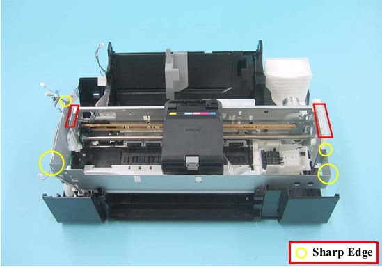
Be careful of the four sharp edges shown in the figure below when assembling or reassembling.
Printer Mechanism Handling Precaution
When lifting the printer, hold parts shown in the figure below to prevent the frame from deforming.
  • Do not touch the PF Scale with bare hands or damage it.
  • If the Printer Mechanism is tilted leftward about 15°, the PF Scale hits against the desk surface and can break. After removing the Printer Mechanism, take extra care to protect the PF Scale.
  • When removing the Waste Ink Tube, take care not to contaminate the printer and surroundings with ink.
  • Extra care must be exercised not to scratch or damage the Waste Ink Tube.
Pull out the Waste Ink Tube by hand.
  • Release the Waste Ink Tube from the groove of the Waste Ink Tray.
  • Release the CR Motor Cable from the two ribs of the Waste Ink Tray
  • Disconnect the connector of the CDR Guide Sensor.
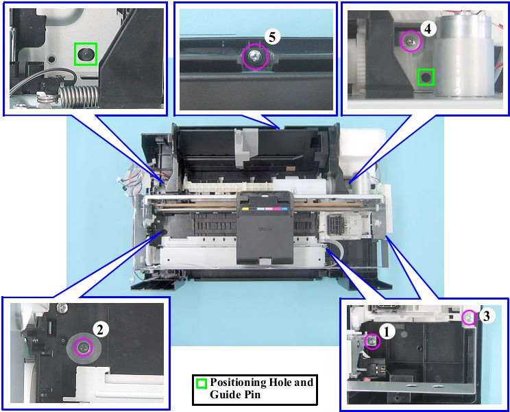
  • Remove the five screws and remove the Printer Mechanism.
Screw : C.B.P.(P2) M3x8 (tightening torque:5-7 kgf.cm) (The numbers shown in the figure indicate the order of tightening the screws.)
When installing the Printer Mechanism, be careful of the following:
  • Wipe off any ink on the joint portion of the Waste Ink Tube before reconnecting the tube. Ink on the joint portion makes the tube likely to get disconnected.
  • Insert the Waste Ink Tube over the tube of the Waste Ink Tray until the top end of the Waste Ink Tube contacts with the rib.
  • Match the positioning holes with guide pins (two pairs) shown.
  • Tighten the screws in the order given.
  • Make sure the Waste Ink Tube or cables are not pinched between the Printer Mechanism and the Housing Lower.
  • Route the CDR Guide Sensor Cable through the opening.

EPSON L800 - L801 - COLOR INKJET PRINTER - ERROR CODES DISPLAY


ERROR CODES
CLICK ON TABLES TO ZOOM IN

Friday, August 02, 2013

BENQ - S-72 LAPTOP - HOW TO REPLACE RAM MODULE & HARD DISC DRIVE


RAM MODULE REMOVAL
Remove 2 screws and RAM door can be removed.
Release the RAM catches on both sides. RAM module can be removed.

HDD REMOVAL
Remove 2 screws and HDD door can be removed.
Pull the HDD carefully with black tape.

AKIRA 14AZ9 - TV MAIN POWER [SMPS] SCHEMATIC [Circuit Diagram] - FULL SCHEMATIC


SMPS SCHEMATIC


CLICK ON SCHEMATIC TO ZOOM IN

Thursday, August 01, 2013

MEMOREX MT-1098 - POWER CONTROL [SMPS] - FA7610CP (Power control)Schematic - [Universal Remote control Setup Codes]


POWER SCHEMATIC
Click on Schematic to Zoom In
Set-up codes
GE universal remote: 000, 001, 004, 006, 009, 031, 046, 049, 051, 082, 083, 135, 162, 268, 310 {0004 0009 0049 0051 0135 0031 0000 0268 0310 0001}
RCA RCR 311W: 1004, 1006, 1013, 1019, 1047, 1054, 1163, 1167, 1205, 1207, 1213, 1230
RCA RCR 312W: 10154, 10463, 10150, 10178, 10016
6 in 1 Super remote: 014,022,062,095,096
Comcast on demand remote control: 0154, 0250, 0463, 0150, 0178, 0179, 0016
Philips SRP-3004 remote control: 1800.

HOW TO ENTER SERVICE MODE - QLS 14TS1020 [CHINA] – MODEL (3P68S-Chassis) – STR-W6553A MAIN POWER REGULATOR SCHEMATIC


SERVICE MODE
  • Enter "factory service mode": Press "MENU","Q.VIEW" and "PP" in turn.
  • Enter "design service mode" : After entering "factory service mode", select "SC" item, then press "8","9"keys. (Normally "design service mode is not needed for production line.)
  • Exit service mode: Press "DISPLAY" key to exit service mode.
Adjustment:
  • In service mode, pressing digital keys directly can enter the corresponding page, pressing "MENU "key can enter the next page, pressing "SCAN" key can enter previous page.
  • Pressing "UP" and" DOWN" keys can select the items to adjust, pressing" LEFT" and" RIGHT" keys can adjust the data values.
BUS OPEN MODE
In service mode, pressing "MUTE" key can enter "BUS OPEN" mode, which is useful for white balance adjustment using AUTO WHITE BALANCE EQUIPMENT or mass data written into EEPROM. IC. Pressing "MUTE" key again can exit "BUS OPEN" mode.
FACTORY MODE
In service mode, pressing "PP" key can enter "FACTORY MODE", which is useful for aging in production lines.  Pressing "PP" key again can exit "FACTORY MODE".
AGING MODE
  • When enter into factory mode state, pressing P.P. key will be permitted to enter Aging of machine mode.
  • Press "8"key and "9"key one by one button exit aging mode.
POWER SUPPLY SCHEMATIC
CLICK ON SCHEMATIC TO ZOOM IN