Friday, July 03, 2015

DC INVERTER AC – HAIER HSU 18HEA – WIRING DIAGRAM – CIRCUIT DIAGRAM – MALFUNCTION CODES

Haier HSU-18HEA03/R2(DB)-I Wall mounted Type DC Inverter E-Series _ Malfunction codes_ Connectors _ Indoor & Outdoor unit wiring diagram – Circuit diagram
In 3 minutes when the compressor stops, the units’ malfunctions are not displayed 
The complete appliance’s malfunctions are prior to the units’ malfunctions.
Malfunction codes of the whole unit Remarks: under the mode of refrigeration, the malfunctions of each unit’s thin pipe temperature sensor are not reported, under the mode of heating, the malfunctions of each unit’s thick pipe temperature sensor are not reported.
MALFUNCTIONS
Connectors - PCB(1) (Control PCB)
CN1,CN2 Connector for power N and L
2 CN3 Connector for ground
3 CN6,CN7 Connector for terminal block
4 CN9,CN10 Connector for CN2,CN1 on the module board
5 CN11 Connector for four way valve coil
6 CN12 Connector for fan motor
7 CN15 Connector for electric expansion valves
8 CN17,CN18,CN19, CN21 Connector for thermistors
9 CN23 Connector for DC POWER 15Vand 5V to the module board
10 CN24 Connector for communicate between the control board and the module board
11 CN28,CN25 Connector to P and N of the module board
12 CN36 Connector for communicate between indoor and outdoor unit.
PCB(2) (module PCB)
CN10 Connector for the DC power 5V and 15V form the control PCB
CN11 Connector for communicate between the control board and the module board

Connector wiring diagram
Indoor unit wiring diagram
Outdoor unit wiring diagram
CIRCUIT DIAGRAMS
Outdoor unit control board circuit diagram
Outdoor unit module board circuit diagram
CLICK ON THE PICTURES TO MAGNIFY

Thursday, July 02, 2015

ERROR CODES and CIRCUIT DIAGRAM - HAIER AIR CONDITIONER

HAIER AU242FHBIA  AU482FIBIA  AU48NFIBJA Air conditioner Error Blinking codes Circuit Diagram
Indoor failure code
A. Wired control type indoor unit: 

The dip switch of wired controller is 1 and 3 at ON, 2 and 4 at OFF.
Failure code Failure description
E0 Float switch abnormal
E1 Outdoor unit failure
E2 Abnormal mode operation
E3 Liquid pipe temperature sensor failure
E4 Gas pipe temperature sensor failure
E5 Repeated indoor unit number (E5 flashes for a while and then turn to E9)
E7 Communication abnormal with EEV box
E8 Communication abnormal between wired controller and indoor PCB
E9 Communication abnormal between indoor and outdoor
EB (pre-set, not available) Water temperature sensor abnormal.
Infrared control type indoor unit:
TIMER lamp flash times Failure description
Once Liquid pipe temperature sensor failure
Twice Gas pipe temperature sensor failure
3 times Ambient temperature sensor failure
4 times Communication abnormal between indoor and outdoor
5 times Communication abnormal with EEV box
10 times Indoor motor abnormal
11 times Float switch or pump motor abnormal
12 times Repeated indoor unit number
13 times Indoor over heat
Note: if indoor RUN lamp flashes, that shows outdoor abnormal, so no matter how many times it flashes, you should check outdoor indicator flash times and the relative failure code.
AU242FH Failure code Failure description
01 Outdoor defrosting temperature sensor TE circuit failure
02 Ambient temperature sensor TA circuit failure
03 Suction temperature sensor TS circuit failure
04 Discharging temperature sensor TD circuit failure
05 Outdoor mid-condenser temperature sensor failure
06 Over current abnormal
07 Current
mutual inductor failure
09 IPM protection
10 EEPROM on PCB incorrect
11 Discharging temperature protection action
13 Pressure switch circuit abnormal
14 Pressure switch circuit abnormal
19 Discharging temperature protection action when in low frequency
20 Communication abnormal when chip 857 receives signal from chip 846
21 Compressor over current failure
22 Communication abnormal when chip 846 receives signal from indoor unit
23 Chip 846 EEPROM
Indoor failure code
AU242FHBIA PCB circuit diagram
AU482FHBIA PCB circuit diagram
AU48NFIBJA PCB circuit diagram

HAIER AU242FHBIA AU482FIBIA AU48NFIBJA Wiring diagram Commercial Air Conditioner

Haier Air-conditioned wiring diagrams [CLICK ON THE DIAGRAMS TO ZOOM IN]
AU242FHBIA WIRING DIAGRAM
AU482FIBIA
AU48NFIBGA
AB**2FCBIA
AE**2FCBKA
AS**2FCBHA
MP3A WIRING DIAGRAM
Click on the Diagrams to Magnify

Wednesday, July 01, 2015

HOW TO DISASSEMBLE Samsung UN32D5500RF Samsung UN40D5500RF LED TV

Disassemble procedure to Samsung LED LCD TVs - UN40D550RF & UN32D5500RF
> Place TV faces down on cushioned table.
> Remove 4 screws from the stand.
> Remove stand.
> Remove the screws of Rear-cover. [32":13 EA - 40":14 EA]
> Lift up the Rear-cover.
> Remove the Left and Right Speaker.
> Remove the 6 screws of Main Board and 5 screws of IP Board.
> Remove the 2 screws of Stand Link Cover.
> Remove the 4 screws of Stand Link.
> Lift up the Stand Link.
> Detach the Pront Hook.
> Lift up the Panel.
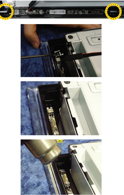
Disassembly:  Function & IR ASSY
Check the 2 Function Clips.
Remove the 2 Function Clips.
Heat the Function Assy by Heat Gun and Lift up the Function Assy.
The sensitivity of function key is available in Factory mode.
CLICK ON THE PICTURES TO ZOOM IN

SANYO 29FS51 NOBLEX 29 Inch CTV HOW TO ENTER SERVICE MODE – Circuit diagram

HOW TO ENTER SERVICE MODE – Power Supply [SMPS] section schematic _ Full Schematic - SANYO 29FS51 NOBLEX 29 Inch CTV
USED ICs _ LA42205-E _ QXXAVC634-N _ QXXAVD111-M

SERVICE MODE
Enter the Service Menu
While pressing the MENU button on the television, press the Number Key 2 on the remote control unit.
Service Adjustments:
Press the CHANNEL UP/DOWN button on the remote control handset to select the desired service menu item you want to adjust.
Use the VOLUME + / - button to adjust the data. The + or - button will increase or decrease the data sequentially.
Exit from the Service Menu
Press the MENU button to turn off the Service Menu display.
The data which is set in the service mode is stored into the memory IC automatically.
When IC802 (EEPROM) is replaced, IC201 (CPU) will automatically write the initial reference data into IC802 for basic TV operation.  However, the bus data should be checked and some bus data should be set up before attempting the service adjustments.
SMPS CIRCUIT DIAGRAM
FULL SCHEMATIC
CLICK ON THE PICTURES TO MAGNIFY

Tuesday, June 30, 2015

LITTMANN STETHOSCOPE How to remove and assemble the Diagram

 How to remove and assemble the Diagram _ LITTMANN STETHOSCOPE
The stethoscope is most often used to listen to heart sounds and breathing. There are two basic types of stethoscopes for respiration system diagnostics of the human body. 
Acoustic Stethoscope
Acoustic stethoscopes are familiar to most people. Acoustic stethoscopes maintain their popularity and trust among doctors due to their longstanding use in the medical profession. Although it is taking digital stethoscopes time to catch up, they are rapidly gaining in popularity. However, acoustic stethoscopes are the most commonly used.
Electronic Stethoscope
Electronic stethoscopes function in a similar way as acoustic stethoscopes, but the sound is converted to electrical signals which can then be amplified and processed for optimal listening. Because the sounds are transmitted electronically, an electronic stethoscope can be a wireless device, can be a recording device, and can provide noise reduction, signal enhancement, and both visual and audio output.
ADVANTAGES & DISADVANTAGES
> In Digital stethoscope Amplifiers are used which amplifies the low level signal.
> Data can be stored for further analysis and consultation.
> Heart signal is displayed on the LCD screen.
> In digital stethoscope battery replacement can be tedious.
> They are expensive.
> They suffer from interference when other electronic instruments like cell phones are around.
PRINCIPLE OF OPERATION
The stethoscope is composed of three major parts. The first part is the chest piece, tubes and headset. It consists of a shallow, bell-shaped piece and a clear, stiff diaphragm, which is connected to the metal earpieces by a flexible tube. The bell is used to pick up lower frequency sounds, and the diaphragm is used for higher frequency sounds. When the chest piece is placed on the skin, vibrations within in the body are amplified by either the bell or diaphragm. These acoustic pressure waves then travel up through the tubing to the earpieces and into the listener’s ears. Digital stethoscopes offer new opportunities for computerized analysis of heart sounds. In cardiac auscultation, an examiner uses a stethoscope to listen to these sounds, which provide important information about the body condition. When the heart sounds are displayed graphically, the methodology is known as phonocardiography. As heart sounds are non-stationary signals, it is important to study both their temporal and frequency contents. Recently, with the rapid development of computer hardware and digital signal processing, heart sounds could be recorded and analyzed easily. The majority of these researchers mainly emphasize on the characteristic extraction by frequency-analysis method. Others concern on how to extract the heart rate from a weeping infant through the heart sound signals, and improve signal-to-noise ratio by adaptive filtering way.
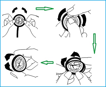
Removing the Diaphragm and Cleaning the Chest-piece.
With the diaphragm side up, grasp the rim with the thumbs and index fingers of both hands and roll the rim off the edge of the chest-piece.
Remove the diaphragm from the rim and clean the parts in soapy water or wipe with alcohol. Chest-piece surfaces can be wiped with alcohol or soapy water.
Dry all parts and surfaces thoroughly before reassembly.
Assembly and Replacement of the Tunable Diaphragm
Using your fingertip, apply a small amount of talcum powder to the inside surface of the flexible edge of the diaphragm.
This will facilitate assembly and maintain smooth and quiet low/high frequency alternation.
Snap the diaphragm with your fingers to remove excess talc.
Insert the flexible edge of the diaphragm into the groove of the rim. This is best accomplished by starting with the rim positioned above the legible side of the diaphragm.
Visually examine the ring to ensure that the flexible edge is smoothly engaged inside the rim. If necessary, flex the assembly by pinching the outer rim edge. between the thumb and fingers.
Repeat this flexing procedure after rotating the assembly one quarter.
To attach the rim/diaphragm assembly to the chest-piece, engage the groove of the rim (with the diaphragm attached) around the chest-piece at one point and hold it in place with your thumbs.
Slowly roll the rim around and over the chest-piece edge using both thumbs, moving in opposite directions around the chest-piece.
Visually inspect the edge where the diaphragm engages the rim for uniform containment.
Minor adjustments may be made by slightly pulling and rolling the rim away from the diaphragm, allowing the diaphragm to slip into position.
Avoid extreme heat, cold, solvents, and oils.
Do not immerse your stethoscope in any liquid or subject it to steam sterilization. If disinfection is required, the stethoscope may be wiped with a 70% isopropyl alcohol solution. Wipe and clean with alcohol or soap water.

SAMSUNG UN32D5500RF UN40D5500RF LED TV No-Power Troubleshooting

No-Power Troubleshooting_Samsung UN32D5500RF _  UN40D5500RF LED TV  Fault symptom & checks
NO POWER
> The LEDs on the front panel do not work when connecting the power cord.
> The SMPS relay does not work when connecting the power cord.
> The units appear to be dead.
The IP relay or the LEDs on the front panel does not work when connecting the power cord if the cables are improperly connected or the Main Board or SMPS is not functioning.  In this case, check the following
>> Check the internal cable connection status inside the unit.
>> Check the fuses of each part.
>> Check the output voltage of SMPS.
>> Replace the Main Board.
Detail Factory Option
If you replace the main board with new one, please change the factory option as well. The options you must change are “Type”.
Main board & T’Con board

Saturday, June 27, 2015

SONY KDL-32BX350 KDL-40BX450 SERVICE MODE - LED BLINKING CODES

How to enter Service Mode - Self Diagnostic Mode - LED blinking codes - Sony KDL-32BX350 KDL-40BX450 LCD TV.
The units in this manual contain a self-diagnostic function. If an error occurs, the STANDBY LED will automatically begin to flash.
The number of times the LED flashes translates to a probable source of the problem.
A definition of the STANDBY LED flash indicators is listed in the instruction manual for the user’s knowledge and reference.
If an error symptom cannot be reproduced, the remote commander can be used to review the failure occurrence data stored in memory to reveal past problems and how often these problems occur.
 DIAGNOSTIC TEST INDICATORS
When an error occurs, the STANDBY LED will flash a set number of times to indicate the possible cause of the problem.
If there is more than one error, the LED will identify the first of the problem areas.
Result for all of the following diagnostic items are displayed on screen.  If the screen displays a “0”, no error has occurred .
DISPLAY OF STANDBY LED FLASH COUNT
LED blinking codes
For errors with symptoms such as “power sometimes shuts off” or “screen sometimes goes out” that cannot be confirmed, it is possible to bring up past occurrences of failure for confirmation on the screen:
To Bring Up Screen Test
In standby mode, press buttons on the remote commander sequentially in rapid succession:
INFO => CHANNEL-5 => VOLUME (--) => TV POWER
SELF DIAGNOSTIC SCREEN DISPLAY
Since the diagnostic results displayed on the screen are not automatically cleared, always check the self-diagnostic screen.
After you have completed the repairs, clear the result display to “0”.
Clearing the Self Check Diagnostic List
1. Error history and Error count : Press the Channel 8 => Channel 0 .
2. Panel operation time : Press the Channel 7 => Channel 0 .

CLICK ON THE PICTURES TO MAGNIFY