Sunday, August 12, 2018

Philips Home Theater System – HTS2500 –Power supply (SMPS) and Power Amplifier schematic, Disassembly, password setting, factory reset and more


Philips DVD-Video, DVD+R/+RW, DVD-R/-RW, CD-R/CD-RW, Audio CD, Video CD/SVCD, Picture CD, MP3-CD, WMA-CD, DivXCD, USB storage device

Amplifier
Total output power ......... 300 W RMS (30% THD) (for:/12/55/05)
Total output power ............................. 240 W RMS (10% THD),...... 300 W RMS (30% THD) (for:/94/98/78)
Power supply ................110-240V, ~50-60 Hz;
Power consumption .................... 55 W
Speakers
System .......................... full range satellite
Speaker impedance..................... 3 ohm
Speaker drivers ........................... 3” full range
Frequency response ................150 Hz-20 kHz
Subwoofer
Impedance ........................................... 12 ohm
Speaker drivers ................................... 133 mm (5.25”) woofer
Frequency response .................40 Hz-150 kHz
Laser specification
Type ..............Semiconductor laser GaAIAs (CD)
Wave length ............... 645 - 665 nm (DVD), 770 - 800 nm (CD)
Output power.........6 mW (DVD), 7 mW (VCD/CD)
Beam divergence .......................... 60 degrees.
Setting procedure & Repair instruction
Restore factory setting
a) Press <SETUP> button on R/C.
b) Select <preference setup> ,then press < OK >.
c) Select <default>,then press <OK> to conf rm.
Version control change
a) Open the Door,then,press “1” “5” “9” on RC.
b) Press <OK> button on RC.
c) TV will show message.
d) If current model doesnot match your set, use down arrow key on the remote to change.
Check on software version
a) Press <SETUP> button on R/C.
b) Select <preference setup> ,then press <OK>.
c) Select <version info>,then press <OK>.
d) TV will show message.
Password change
a) Press <SETUP> button on R/C.
b) Select <preference setup> ,then press <OK>.
c) Select <password> <change>,then press <OK> to confrm “0000” is default password supplied.
Trade mode
a) Press <Open/Close>button on R/C.
b) Press “2” “5” “9” on R/C,VFD will display “TRA ON “ or “TRA OFF
Upgrading new software
a) Check for the latest software version on www.philips.com/support.
Search for your model and click on ‘software&drivers’.
b) Copy the latest upgrading software onto a CD-R or USB storage device.
c) Insert the CD-R program disc or connect the USB storage device to the home theater.
d) Press <USB> button on R/C.
e) TV will show message
f) Press <PLAY> “>||” button on R/C.
g) TV will show message.
h) When the updated is complete ,the home theater automatically switch to standby.
Note: when upgrade in progress, please do not unplug or switch off the device.
How to replace the defective DVD Loader
a) Remove the defective DVD Loader..
b) Accordingly connect DVD Loader and “CN201”, “CN203” on the top of main board as shown here.:
c) Remove solder joint on the ESD protection point
Note: The ESD protection point on the Top side view of OPU must
be soldered if
- the DVD Loader is OK and needs to be disconnected from connector “CN201” and “CN203” of the main board.
- the defective DVD Loader is needed to be send back to supplier for failure analysis and to support back charging evidence.
Produce to change Tuner grid (only for /98 version)
In some countries, you can switch the FM tuning grid between 50 kHz and 100 kHz. Changing the tuning grid erases all preset radio stations.
a) Press<radio> button on R/C
b) Press <Stop> button on R/C.
c) Press and hold <Play> until (50 kHz) or (100 kHz) is displayed.
Note: repeating the same action will toggle back to it previous tuning grid setting.
Disassembly
Open the DVD Tray by using the Open/Close Button while the Set is ON and disconnect the mains supply after removing the Tray Cover.
Note: If this is not possible, the DVD Tray has to be open manually.
Take a mini screw driver about 2mm diameter and make a marking 24mm from the tip as shown in figure 2 . Place the set on its side, insert the mini screw driver till the marking and slide it towards the left as shown in figure 1 until the Tray moves out of the Front Panel.
2) Return the set to its upright position and remove the Tray Cover as shown in Figure 3 and close the tray manually by pushing it back in
3) Loosen 6 screws and remove the Top Cover by lifting the rear portion upwards before sliding it out towards the rear.
- 4 screws “A” at the back panel as shown in figure 4.
- 1 screw “B” each on the left & right side as shown in figure 5
Dismantling of the DVD Loader Module
1) Loosen 4 screws “ C “ at the DVD Loader Module as shown in figure 6.
Dismantling of the VFD+USB Board
Loosen 7 screws “D” on the top of VFD+USB Board as shown in figure 7.
Dismantling of the MAIN Board
1) Loosen 4 screws “ E ” on the top of MAIN Board as shown in figure 8.
2) Loosen 5 screws “ F ” at the back panel as shown in figure 9.
Dismantling of the POWER Board
1) Loosen 5 screws “G ” on the top of Power Board as shown in figure 10
Wiring diagram
SMPS PWB and schematic
Power Amplifier schematic


Saturday, August 04, 2018

Pioneer CD RDS RECEIVER DEH-2350UB - Error codes, Service mode, service adjustments, disassembly and more

Pioneer car audio - DEH-2350UB/XNES, DEH-2350UBG/XNES, DEH-2350UBSW/XNES, DEH-2350UB/XSES, DEH-2350UB/XNES1
Rated power source...............14.4 V DC
(allowable voltage range: 12.0 V to 14.4 V DC)
Maximum power output .......50 W × 4
Continuous power output ...22 W × 4 (50 Hz to 15 000 Hz, 5 % THD, 4 load, both channels driven)
Load impedance ......................4 (4 to 8 allowable)
With a 2 speaker system, do not connect anything to the speaker leads that are not connected to speakers.
Power amp (sold separately)
Error codes
If a CD memory device is inoperable, or operation of such media is stopped by an error, the error mode is established and a cause of the error is displayed by an error code. Indication of error codes is intended to reduce the number of calls from customers and facilitate failure analysis and repair work in servicing.
Display method
If “0xFD” error mode is displayed in CD MODE (CD MODE area for display), an error code will be displayed in the MIN (minute display) and SEC (second display) areas,
The same code is displayed in the MIN and SEC areas.
The TNO area is blank (#0FFH), as it conventionally was.
• Display example of the main unit
Depending on the display capability of LCDs, the display format varies, as shown below. XX denotes an error number.
Note: In a case of an OEM product, the error display format is subject to the specifications used by the equipment manufacturer,
• Indications of error codes are available only during disc operations, because CD operations are unavailable if a mechanical error is generated.
• If the TOC cannot be read, this is not processed as an error, and operation continues accordingly.
• If you design a new head unit, be sure to use one of the display formats indicated in “Display example of the main unit.”
The 2 high-order digits of an error code denote the main
classification, shown below.
0x: Servo-related errors
1x: Servo-related errors
3x: Servo-related errors
5x: Mechanism-related errors
How to restore from each error is shown below.
0x, 1x and 3x: ACC-OFF then ON, CD-OFF then ON, Disc ejection
5X: ACC-OFF then ON, Disc ejection, Disc reloading.

Error codes and connector descriptions
Software update
The software of this product is stored in IC671.  Replace IC671 when making the version upgrade of software.
Service mode:  display test mode
The information such as the system microcomputer version is checked.
How to enter Test mode
Press “ 1 ” and “ 3 ” keys simultaneously to start resetting.
Operation key:  1 + 3
Processing:  Enter display test mode (2) Switch to next test mode.
Test items and CD Test mode details
After the [EJECT] key is pressed keys other than the [EJECT] key should not be pressed, until disc ejection is complete. When the key [2] or [3] is pressed during the Focus Search, the power supply should be immediately turned off (otherwise the lens sticks to Wall, causing the actuator to be damaged).
100TR Jump, the mechanism shall be set to the Tracking Close mode when the key is released.
When the power is turned on/off the gain of the RFAMP is reset to 0 dB. At the same time all the self-adjusting values shall return to the default setting.
Do not do Tracking Servo Close before doing Focus Servo Close. (Because the over current flows)
Disassembly
CD adjustment
Cautions on adjustments
In this product the single voltage (3.3 V) is used for the regulator. The reference voltage is the REFO1 (1.65 V) instead of the GND.
If you should mistakenly short the REFO1 with the GND during adjustment, accurate voltage will not be obtained, and the servo’s misoperation will apply excessive shock to the pickup. To avoid such problems:
a. Do not mix up the REFO1 with the GND when connecting the (-) probe of measuring instruments.  Especially on an oscilloscope, avoid connecting the (-) probe for CH1 to the GND.
b. In many cases, measuring instruments have the same potential as that for the (-) probe. Be sure to set the measuring instruments to the floating state.
c. If you have mistakenly connected the REFO1 to the GND, turn off the regulator or the power immediately.  Before mounting and removing filters or leads for adjustment, be sure to turn off the regulator.
For stable circuit operation, keep the mechanism operating for about one minute or more after the regulator is turned on.
In the test mode, any software protections will not work. Avoid applying any mechanical or electrical shock to the mechanism during adjustment.  The RFAGC and RFO signals with a wide frequency range are easy to oscillate. When observing the signals, insert a resistor of 1k ohms in series.
The load and eject operation is not guaranteed with the mechanism upside down. If the mechanism is blocked due to mistaken eject operation, reset the product or turn off and on the ACC to restore it.
Test mode
This mode is used to adjust the CD mechanism module.
To enter the test mode.
[4] + [6] -> BUP + ACC ON
To exit from the test mode.
Turn off the ACC and back up.
Notes:
a. During ejection, do not press any other keys than the EJECT key until the loaded disc is ejected.
b. If you have pressed the key during focus search, turn off the power immediately to protect the actuator from damage caused by the lens stuck.
c. For the TR jump modes except 100TR, the track jump operation will continue even if the key is released.
d. For the CRG move and 100TR jump modes, the tracking loop will be closed at the same time when the key is released.
e. When the power is turned off and on, the jump mode is reset to the single TR (91), the RF amp gain is set to 0 dB, and the auto-adjustment values are reset to the default settings.
Checking the grating after changing the pickup unit
The grating angle of the PU unit cannot be adjusted after the PU unit is changed. The PU unit in the CD mechanism module is adjusted on the production line to match the CD mechanism module and is thus the best adjusted PU unit for the CD mechanism module. Changing the PU unit is thus best considered as a last resort. However, if the PU unit must be changed, the grating should be checked using the procedure below.
Symptoms of Mal-adjustment:
If the grating is off by a large amount symptoms such as being unable to close tracking, being unable to perform track search operations, or taking a long time for track searching.
Checking Procedure
1. In test mode, load the disc and switch the 3 V regulator on.
2. Using the right and left buttons, move the PU unit to the innermost track.
3. Press key 3 to close focus, the display should read "91". 
Press key 2 to implement the tracking balance adjustment the display should now read "81". Press key 3. The display will change, returning to "81" on the fourth press.
4. As shown in the diagram  monitor the LPF outputs using the oscilloscope and check that the phase difference is within 75 .
5. If the phase difference is determined to be greater than 75 try changing the PU unit to see if there is any improvement. If, after trying this a number of times, the grating angle does not become less than 75 then the mechanism should be judged to be at fault.
Note:
Because of eccentricity in the disc and a slight misalignment of the clamping center the grating waveform may be seen to "wobble" ( the phase difference changes as the disc rotates). The angle specified above indicates the eaverage angle.
Hint
Reloading the disc changes the clamp position and may decrease the "wobble”

Friday, July 27, 2018

32PFS6402/12 Philips LCD TV – service mode, Factory mode, Software update, Error codes and more

How to enter the service mode, firmware update, error codes or LED blinking codes - Philips 32 inch LCD TV - 32PFS6402
There are critical components used in LCD color TVs that are important for safety. These components are identified with shading and  mark on the schematic diagrams and the parts list. It is essential that these critical parts be replaced only with the part number specified in the parts list to prevent electric shock, fire, or other hazard.
An isolation transformer should be used during any service to avoid possible shock hazard, in case of live chassis.
During the repair, DO NOT leave the Power On for more than 1 hour while the TV is face down on a cloth.
Readings are taken with a color-bar signal input.
Readings are taken with a 10MΩ digital multimeter.
Voltages are DC with respect to ground unless otherwise noted.
Voltage variations may be noted due to normal production tolerances.
All voltages are in V
Service Modes
The Service Mode feature is split into following parts:
Service Alignment Mode (SAM).
Factory Mode.
Customer Service Mode (CSM).SAM and the Factory mode offer features, which can be used by the Service engineer to repair/align a TV set.
SAM and the Factory mode offer features, which can be used by the Service engineer to repair/align a TV set. Some features are:
Make alignments (e.g. White Tone), reset the error buffer(SAM and Factory Mode).
Display information (“SAM” indication in upper right corner of screen, error buffer, software version, operating hours, options and option codes, sub menus).
The CSM is a Service Mode that can be enabled by the consumer. The CSM displays diagnosis information, which the customer can forward to the dealer or call centre. In CSM mode, “CSM”, is displayed in the top right corner of the screen. The information provided in CSM and the purpose of CSM is to: Increase the home repair hit rate.
Decrease the number of nuisance calls. Solved customers’ problem without home visit.
(For the new model range, a new remote control (RC) is used with some renamed buttons. This has an impact on the activation of the Service modes. For instance the old “MENU” button is now called “HOME” (or is indicated by a “house” icon).)
Service Alignment Mode (SAM)
Purpose
To modify the NVM.
To display/clear the error code buffer.
To perform alignments.
Specifications
Operation hours counter (maximum five digits displayed).
Software version, error codes, and option settings display.
Error buffer clearing.
Option settings.
Software alignments (White Tone).
NVM Editor.
Set screen mode to full screen (all content is visible).
How to Activate SAM
To activate SAM, use one of the following methods:
Press the following key sequence on the remote control transmitter: “062596”, directly followed by the “INFO/OK” button. {Do not allow the display to time out between entries while keying the sequence.}
Or via ComPair.
After entering SAM, the following items are displayed,
with “SAM” in the upper right corner of the screen to indicate that the television is in Service Alignment Mode.
How to Navigate
In the SAM menu, select menu items with the UP/DOWN keys on the remote control transmitter. The selected item will be indicated. When not all menu items fit on the screen, use the UP/DOWN keys to display the next/previous menu items.
With the “LEFT/RIGHT” keys, it is possible to:
(De) activate the selected menu item.
(De) activate the selected sub menu.
Change the value of the selected menu item.
When you press the MENU button once while in top level SAM, the set will switch to the normal user menu (with the SAM mode still active in the background).
How to Store SAM Settings
To store the settings changed in SAM mode (except the RGB Align settings), leave the top level SAM menu by using the POWER button on the remote control transmitter or the television set. The mentioned exceptions must be stored separately via the STORE button.
How to Exit SAM
Use one of the following methods:
Switch the set to STANDBY by pressing the mains button on the remote control transmitter or the television set.
Via a standard RC-transmitter, key in “00” sequence.
Note: When the TV is switched “off” by a power interrupt while in SAM, the TV will show up in “normal operation mode” as soon as the power is supplied again. The error buffer will not be cleared.
Factory mode
Purpose
To perform extended alignments.
Specifications
Displaying and or changing Panel ID information.
Displaying and or changing Tuner ID information.
Error buffer clearing.
Various software alignment settings.
Testpattern displaying.
Public Broadcasting Service password Reset.etc
How to Activate the Factory mode
To activate the Factory mode, use the following method:
Press the following key sequence on the remote control transmitter: from the “menu/home” press “1999”, directly followed by the “Back/Return” button.
Do not allow the display to time out between entries while keying the sequence.
After entering the Factory mode, we can see many items displayed, use the UP/DOWN keys to display the next/previous menu items.
How to Exit the Factory mode
Use one of the following methods:
Select EXIT_FACTORY from the menu and press the “OK” button.
Note: When the TV is switched “off” by a power interrupt, or normal switch to “stand-by” while in the factory mode, the TV will show up in “normal operation mode” as soon as the power is supplied again. The error buffer will not be cleared.
Customer Service Mode (CSM)
Purpose
The Customer Service Mode shows error codes and information on the TVs operation settings.The call centre can instruct the customer (by telephone) to enter CSM in order to identify the status of the set.This helps the call centre to diagnose problems and failures in the TV set before making a service call.The CSM is a read-only mode; therefore, modifications are not possible in this mode.
Specifications
Ignore “Service unfriendly modes”.
Line number for every line (to make CSM language independent).
Set the screen mode to full screen (all contents on screen is visible).
After leaving the Customer Service Mode, the original settings are restored.
Possibility to use “CH+” or “CH-” for channel surfing, or enter the specific channel number on the RC.
How to Activate CSM
To activate CSM, press the following key sequence on a standard remote control transmitter: “123654” (do not allow the display to time out between entries while keying the sequence). After entering the Customer Service Mode, the following items are displayed. use the Right/Left keys to display the next/previous menu items
Note: Activation of the CSM is only possible if there is no (user) menu on the screen.
How to Navigate
By means of the “CURSOR-DOWN/UP” knob (or the scroll wheel) on the RC-transmitter, can be navigated through the menus.
How to Exit CSM
To exit CSM, use one of the following methods.
Press the MENU/HOME button on the remote control transmitter.
Press the POWER button on the remote control transmitter.
Press the POWER button on the television set.
Software Upgrading, Error code and Panel Code
Software Upgrading
5.1.1. The following update is for .pkg file.
1. Rename the file to “upgrade_loader.pkg”
2. Prepare a USB memory.
3. Copy the software to USB flash disk(root directory).
4. Switch off the TV and Insert the USB memory stick that contains the software update files in one of the TV’s USB 2.0 ports.
Note: It contains USB3.0 port, if connect on it, the software may can’t be detected.
5. Switch on the TV. The TV will detect the USB memory s tick automatically. Then a window jumps out as below.
6. When the TV software is updated, the TV will turn on again automatically. Remove your USB flash drive.
7. We can enter in CSM or Factory mode to check the current software version.
5.1.2. The following update is for .upg file.
Step 1: Ready for F/W Upgrade
1. Prepare a USB memory.
2. Copy the software to USB flash disk(root directory).
Note the version of this F/W before you change the software file name.
Step 2: F/W Upgrade
1. Plug the USB memory on the USB port on the side I/O port of TV (Please connect to USB 2.0 port, not recommend USB3.0 port)
2. AC on (Power plug)
3. TV will show message as below image, Press [Start] to detect the software automatically.
Press [Start] to start software upgrade
Upgrade in progress
Step 3: Check the SW version
1. After burning software, TV will restart
2. Press “Menu+1999+back”, enter Factory mode to check if the software version is correct
Caution: Please make sure that software upgrade is finished before unplug the USB and AC power.
Error codes are required to indicate failures in the TV set. In principle a unique error code is available for every
• Activated (SW) protection.
• Failing I2C device.
• General I2C error.
The last five errors, stored in the NVM, are shown in the Service menu’s. This is called the error buffer.
The error code buffer contains all errors detected since the last time the buffer was erased. The buffer is written from left to right. When an error occurs that is not yet in the error code buffer, it is displayed at the left side and all other errors shift one position to the right.
An error will be added to the buffer if this error differs from any error in the buffer. The last found error is displayed on the left.
An error with a designated error code never leads to a deadlock situation. It must always be diagnosable (e.g. error buffer via OSD or blinking LED).
In case a failure identified by an error code automatically results in other error codes (cause and effect), only the error code of the MAIN failure is displayed.
How to Read the Error Buffer
You can read the error buffer in three ways:
• On screen via the SAM/CSM (if you have a picture).
Example:
– ERROR: 000 000 000 000 000: No errors detected
– ERROR: 013 000 000 000 000: Error code 13 is the last and only detected error
– ERROR: 034 013 000 000 000: Error code 13 was detected first and error code 34 is the last detected (newest) error
• Via the blinking LED procedure (when you have no picture).
Error codes overview
In this chassis only “layer 2” error codes are available and point to problems on the SSB. They are triggered by LED blinking when CSM is activated. Only the following layer 2 errors are defined:
How to Clear the Error Buffer
The error code buffer is cleared in the following cases:
• By using the CLEAR command in the SAM menu
• By using the CLEAR command in the Factory mode:
• By using the following key sequence on the remote control transmitter: “062599” directly followed by the OK button.
• If the contents of the error buffer have not changed for 50 hours, the error buffer resets automatically.
Note: If you exit SAM by disconnecting the mains from the television set, the error buffer is not reset.
Panel Code
Press the following key sequence on a standard RC transmitter: “062598” directly followed by MENU and “xxx”, where “xxx” is a 3 digit decimal value of the panel type: see column “Display Code” in below tab. After resetting the Display Code, restart the set immediately.
CTN_ALT BOM#:  32PFS6402/12  
Panel Type: TPT315B5-FHBN0.K S4DP2P 
Set Option Code: 133
Power Supply Unit
All power supplies are a black box for Service. When defective, a new board must be ordered and the defective one must be returned, unless the main fuse of the board is broken. Always replace a defective fuse with one with the correct specifications! This part is available in the regular market.
Consult the Philips Service web portal for the order codes of the boards.
Important delta’s with the platform are:
• New power architecture for LED backlight
• “Boost”-signal is now a PWM-signal + continuous variable
The control signals are:
• PS-ON
• Lamp “on/off”
• DIM (PWM) (not for PSDL)
In this manual, no detailed information is available because of design protection issues.
• +8.5V output (standby mode)
• +12 output (on-mode)
• +12V_audio (audio AMP power)
• Output to the display; in case of
- IPB: High voltage to the LCD panel
- PSL and PSLS (LED-driver outputs)
- PSDL (high frequent) AC-current.
Diversity
The diversity in power supply units is mainly determined by the diversity in displays.
The following displays can be distinguished:
• CCFL/EEFL backlight: power panel is conventional IPB
• LED backlight:
- side-view LED without scanning: PSL power panel.
- side-view LED with scanning: PSLS power panel
- direct-view LED without 2D-dimming: PSL power panel
- direct-view LED with 2D-dimming: PSDL power panel.
PSL stands for Power Supply with integrated LED-drivers.
PSLS stands for a Power Supply with integrated LED-drivers with added Scanning functionality (added microcontroller).
PSDL stands for a Power Supply for Direct-view LED backlight with 2D-dimming.
DC/DC Converters
The on-board DC/DC converters deliver the following voltages(depending on set execution):
• +3V3-SB, permanent voltage for the Stand-by Power system
• +3V3-STANDBY,voltage for IR/Key board
• +12V, input from the power supply for the panel common(active mode)
• 12V, input from the power supply for LNB supply
• +3V3-EMMC, voltage for EMMC when TV on
• TUNER_3V3, supply voltage for tuner
• +5V-SW, input intermediate supply voltage for USB Power
• +12V-AUDIO1 for the AUDIO AMP
• +3.3VA_T2, voltage for Demodulator IC channel decoder.
Video and Audio Processing - MT5593FPIJ
The MT5593FPIJ is the main audio and video processor (or System-on-Chip) for this platform. It has the following features:
• ATSC /DVB-T /DVB-C/DTMB demodulators
• Ture 120HZ Full HD MJC
• Power CPU core
• 3D graphic support OpenGL ES 1.1/2.0
• A muti-standard video decoder
• A transport de-multiplexer
• One HDMI 2.0 receiver with 3D support
• MHL2.0& Standby charging
• 2D/3D converter
• Rich format audio codec
• Local dimming (LED backlight)
• Ethernet MAC+PHY
• TCON
• Panel overdrive control
• Four-link LVDS, mini-LVDS,V-by-one, EPI
The MT5593FPIJ family consists of a DTV front-end demodulator, a backend decoder and a TV controller and offers high integration for advanced applications. It integrates a transport de-multiplexer, a high definition video decoder, an audio decoder, a four-link LVDS transmitter, a mini-LVDS transmitter, a V-by-one transmitter, an EPI transmitter, and an NTSC/PAL/SECAM TV decoder with 3D comb filter(NTSC/PAL).
The MT5593FPIJ enables consumer electronics manufacturers to build high quality, low cost and feature-rich DTV. The MT5593PFIJ family supports Full-HD MPEG1/2/4/H.264/VC1/RM/AVS/ and H.264/HEVC video decoder standards, and JPEG. The MT5593FPIJ also supports edia Tek MDDi de-interlace solution which can reach very smooth picture quality for motions. A 3D comb filter added to the TV decoder recovers great details for still pictures.
The special color processing technology provides a natural, deep colors and true studio quality video. Moreover, the MT5593 family has built-in high resolution and high-quality audio codec. The MT5593FPIJ family provides consumers with and Full-HD 120Hz experience. It integrates high-quality Full-HD ME/MC technology. The MT5593FPIJ family supports ASTC,DVB-T and DVB-C,DTMB demodulation functions. It reserves transport stream inputs for external demodulators for other countries or areas.TV maker can easily port the same UI to worldwide TV models. First-class adjacent and co-channel rejection capability grants excellent reception. Professional error-concealment provides stable, smooth and mosaic-free video quality.

Wednesday, July 18, 2018

Sylvania 6620LDF – LCD TV-DVD combo – service mode adjustments, firmware renewal, initialization, SMPS schematic and more

How to set up the service mode
1. Use the service remote control unit.
2. Turn the power on. (Use main power on the TV unit.)
3. Press [DISC MENU] button on the service remote control unit. Version of micro computer will be displayed on the LCD or display. (Ex: A95FP-0.23)
How to make Service remote control unit
Prepare normal remote control unit (Part No. NE240UD). Remove 3 screws from the back lid.
Cut off pin 10 of the remote control.
microprocessor and short circuit pins 10 and 17  with a jumper wire.
Initial Setting
General: Enter the Service mode. Set the each initial data as shown on table below
Flicker Adjustment
1. Enter the Service mode.
2. Press [2] button on the remote control unit.  The following screen appears.
If Flicker Adjustment is not fit, the screen becomes the following.
Press [CH. UP / DN] buttons on the remote control unit so that flash stops.
White Balance Adjustment
Purpose: To mix red, green and blue beams correctly for pure white.
Symptom of Misadjustment: White becomes bluish or reddish.
Use the remote control unit.
1. Operate the unit for more than 20 minutes.
2. Input the White Purity (APL 80%).
3. Set the color analyzer to the CHROMA mode and bring the optical receptor to the center on the LCD-Panel surface after zero point calibration as shown.
Note: The optical receptor must be set perpendicular to the LCD Panel surface.
[RF/VIDEO1]
Enter the Service mode. 
Press “VOL DN” button on the remote control unit and select “C/D1-” mode.
[VIDEO2]
Enter the Service mode. 
Press “VOL DN” button on the remote control unit and select “C/D2-” mode.
[RF/VIDEO1]
When “x” value and “y” value are not within specification, adjust “DB (C/D1)” or “DR (C/D1)”.
Refer to “1. Initial Setting.”
Note: “DB(C/D1)” or “DR(C/D1)” must be adjusted within ±0.01.
[VIDEO2]
When “x” value and “y” value are not within specification, adjust “DB(C/D2)” or “DR(C/D2)”.
Refer to Initial Setting.”
Note: “C-DB(C/D2)” or “C-DR(C/D2)” must be adjusted within ±0.01.
Turn the power off and on again. (Main power button on the TV unit.)
To initialize the lCD TV/DVD
To put the program back at the factory-default, initialize the LCD TV/DVD as the following procedure
DVD Section
1. Press [1], [2], [3], [4], and [DISPLAY] buttons on the remote control unit in that order.
Press [CLEAR] button on the remote control unit. 
When “OK” appears on the screen, the factory default will be set.
3. To exit this mode, press [CH. UP/DN] or [SELECT] button to go to TV mode, or press [POWER] button to turn the power off.
LCD TV Section
1. Turn the power on. (Use main power on the TV unit.)
2. To enter the service mode, press [DISC MENU] button on the service remote control unit.
- To cancel the service mode, press [POWER] button on the remote control.
3. To initialize the LCD television, press [DISPLAY] button on the remote control unit.
4. Confirm "FF" indication on the upper right of the screen.
5. Unplug the AC cord.
Firmware renewal
1. Turn the power on and press [EJECT] button on the remote control unit to put the LCD TV/DVD into DVD mode. Then remove the disc.
2. To put the LCD TV/DVD into F/W version up mode, press [9], [8], [7], [6], and [SEARCH MODE] buttons on the remote control unit in that order.
Firmware update screen appears.
3. Insert the disc for version up into the disc slot.
4. The LCD TV/DVD enters the F/W version up mode automatically. 
If you enter the F/W for different models, “Disc Error” will appear on the screen, then the disc will be ejected automatically.
5. After programming is finished, the disc will be ejected automatically,  and the checksum will be shown.
At this time, no button is available.
6. Remove the disc.
7. Press [CH. UP/DN] button on the unit to go to TV mode, or press [POWER] button on the unit to turn the power off.
8. Press [EJECT] button on the remote control unit to put the LCD TV/DVD into DVD mode again.
9. Press [1], [2], [3], [4], and [DISPLAY] buttons on the remote control unit in that order.
10.Press [CLEAR] button on the remote control unit.
When “OK” appears on the screen, the factory default will be set. Then the firmware renewal mode is complete.
11.To exit this mode, press [CH.UP/DN] or [SELECT] button to go to TV mode, or press [POWER] button to turn the power off.
Voltage indications for PLAY and STOP modes on the schematics are as shown
How to Eject Manually
1. Remove the Rear Cabinet.
2. To remove the Loader PCB Holder with the DVD Main CBA Unit, remove three screws.
    Do not disconnect connectors.
3. To remove the Chassis Cover, remove 4 screws A as shown in Fig.
4. Remove a disc.
Reassembly note of the Chassis Cover:
Insert the pin A on the Chassis Cover into the hole A on the Main Chassis as shown in above Fig.
Audio section schematic: Main PWA
Inverter Schematic and PWA
                               
Power (SMPS) Schematic: Main CBA
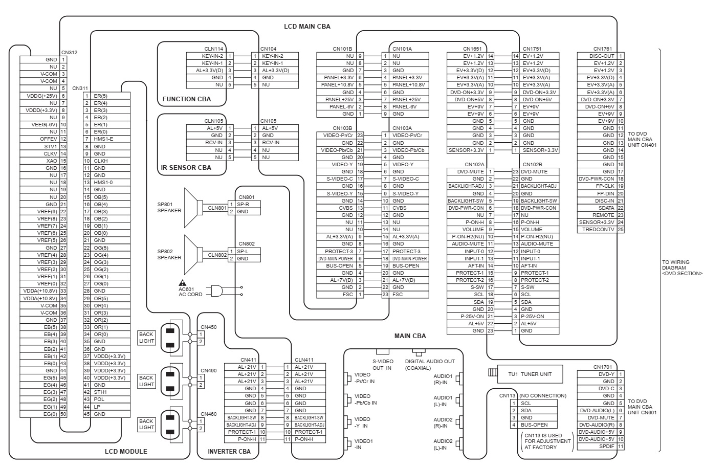
Wiring diagram

Friday, July 13, 2018

LG 29FS4RK, LG 29FS4RK-L1 – 29 inch CTV – schematic and service adjustments

Used ICs: TDA7297(Audio amplifier), TDA120xx(UOC), TDA6107ajf(RGB Amp),TDA9326(Vertical amp), 2SC6090(Horizontal Out Transistor), STR6556(SMPS control), BSC2B-N2334(FBT)
(1) Because this is an insulated chassis, it is not necessary use an isolation transformer. However, the use of the isolation transformer will help protect the test instrument.
(2) The adjustment must be made in the correct order.
(3) The adjustment must be made given the circumstance of 25 ± 5 ° C temperature and 65 ± 10% relative humidity if there is no specific designation.
(4) The AC input voltage of the receiver must maintain a nominal voltage during adjustment.
(5) The receiver must be operated for about 15 minutes before to make the adjustment.
(6) Signal: The standard color signal is approved in 65 ± 1dBμV. The standard color signal means the pattern signal digital.
Adjustment
Adjust the volume of the Top Focus of the FBT for the best focus of the vertical line of the fourth part of the screen (Red circle)
Manual Screen Adjustment
(Using ADJ (ADJUST) of the Remote Control)
(1) Receive the NTSC (PAL) signal in RF mode without considering the channel.
(2) If you press the "ADJ" button in the LINE SVC mode (INSTART button), the LINE SVC mode changes to the setting mode of the screen.
(3) Adjust the SCREEN so that all OK appears on the HBC and WBC using SCREEN VOL. FBT (Press the button ADJ to exit SVC mode)
Sub-brightness adjustment
(1) If you press the "ADJ" button on the remote control to adjust Setting mode "SCREEN" (SCREEN), the mode changes to the Secondary Brightness setting mode.
(Sub-brightness adjustment mode: Channel 14, MIN CONTRAST / BRIGHTNESS)
(2) Adjust until the "2" almost disappears in the Scale of Gray of the Monoscope signal using the VOL +, - key.
Manual Adjustment of White Balance
NOTE: When adjusting the white balance automatically, connect the JIG setting in the LINE SVC MODE. (When press the IN-START, MUTE button on the control remote to adjust neatly, it changes to AUTO MODE and on the Left / Top part of the screen displays "AUTO").
(1) Receive 100% of the white pattern.
(2) Set the LOW Light state (4.5FL) of BLO-R (R CUT), BLO-G (G CUT).
(3) Set the status of HIGH Light (35FL) of RG (R DRIVE), GG (G DRIVE) to BG (B DRIVE): 32.
(4) Repeat the previous steps (2) and (3) for the best condition of each state of High Light and Low Light.
X: 282, Y: 288 (Color Temperature: 10000oK
Adjustment of Deflection Data
 (1) Receive the Digital Pattern.
(2) Use the Remote Control for adjustment.
(3) Select SERVICE 2 in the SERVICE MENU by pressing the LINE SVC MODE (IN-START KEY) and enter the mode Deflection adjustment by pressing the VOL + key.
(4) Use the CH +, CH - key to select the item of adjustment.
(5) Use the VOL +, VOL - key to increase / decrease the data Adjustment
(1) First, adjust the deflection data in N50Hz (PAL) and adjustment to N60Hz (NTSC), Z60Hz, N50Hz, W50Hz, Z50Hz. (with the ARC Model)
(2) Only adjust in N60Hz (NTSC).
(3) After finishing the deflection setting, press the ENTER key to enter (before pressing the INSTART key) or exit in Service mode. (OUTPUT KEY)
V SLOPE
When you select the Adjustment Mode V SLOPE, half of the lower screen is blank.
At this time, adjust the Clearing Line and the line vertical geometric center so that they are equal.
 V SHIFT
Adjust so that the horizontal centerline of a pattern of digital circle matches the horizontal center geometry of the CPT.
 V LINEAR
Adjust until the top and bottom of the screen are symmetrically equal in the Digital Pattern.
 V AMPLIT (V AMPITUDE)
1) PAL signal: Adjust so that the circle of a pattern of digital circle is located at an interval of 6 ~ 7mm from the effective CPT screen.
2) NTSC signal: Adjust so that the circle of a pattern of digital circle can be located inside the screen effective CPT
 H SHIFT
Adjust so that the vertical centerline of a pattern of digital circle matches the geometric vertical center of the CPT.
Schematic and PWB
 EW WIDTH
Adjust so that a digital circle pattern resembles to an exact circle.
 EW PARAB (EW PARABOLA)
Adjust so that the middle portion of the vertical line left and right outermost seem parallel with the vertical lines of the CPT.
 EW TRAPE (EW TRAPEZOID)
Adjust to make the length of the upper horizontal line be equal to the bottom horizontal line
 EW UPCOR & EW LOCOR
After finishing the EP adjustment, adjust the vertical line on the lower left, lower right, upper left, and top right of the screen to the best straight line
 H BOW
After finishing the EP adjustment, adjust until symmetric the top and bottom corner of the screen.
 H PARALL (ANGLE)
Adjust the vertical slope.
 SCORRECT (S CORRECTION)
Adjust so that all distances between each width of the upper / central / lower trellis are equal.
  Setting the value of the CPT Default (Initial) data has I like that, because it is decided by the value of CPT DY.
 V SCROLL
Save the initial configuration values.
v ZOOM
Setting the value of the CPT Default (Initial) data has I like that, because it is decided by the value of CPT DY.