Thursday, June 18, 2020

BOSE SoundTouch Wireless Adapter – air play and non air play – WiFi module test - factory reset - USB port test - disassembling – teat procedure

BOSE SoundTouch Wireless Adapter DISASSEMBLY PROCEDURES

1. Top Cover Removal
1.1 With the unit upside down, remove the three screws that secure to two halves of the enclosure together.
1.2 Lift off the bottom enclosure. It will come off with the Wi-Fi PCB assembly mounted in the bottom of it, attached to the I/O board with two ribbon cables. The I/O PCB assembly is mounted to the upper enclosure plastic.

2. I/O PCB Assembly Removal

2.1 Perform procedure 1.
2.2 Remove the two screws that secure the I/O PCB assembly to the upper housing. Lift out the board.
Note: Retain the connector scrim and the reset button scrim for re-use.
2.3 Disconnect the Bose link cable at J201. Disconnect the ribbon cables and J200 and J300.
Note: The Bose link cable is not easily replaceable. It comes as a service part, included with the top housing, pressed in place.

3. Wi-Fi Module PCB Removal
3.1 Perform procedure 1.
3.2 Remove the one screw that secures the Wi-Fi board to the bottom housing. Lift out the PCB assembly.
3.3 Disconnect the two ribbon cables at J1201 and J1203.
Note: Due to complexity, the Wi-Fi module PCB assembly is not repairable at the component level. If you suspect it has failed, you will need to replace the board.

TAP COMMAND SETUP

Note: The SoundTouch wireless adapter is powered by +12 over its Bose link cable. You will need to connect the wireless adapter to a compatible SoundTouch product such as an SA-4 amplifier, Stereo JC music system bass module or a Lifestyle SoundTouch media center in order to provide power to it for the following tests.
TAP command setup
Equipment Required:
Hardware
# Computer w/serial port
# RS232 to TTL converter
# Lifestyle ETAP Cable, P/N 264565
# SoundTouch product, SA-4 amplifier or other compatible
Software
# TeraTerm terminal emulator 
TAP commands are sent to the SoundTouch wireless adapter by connecting to the SERVICE connector on the back of the adapter. An ETAP cable and RS232 to TTL Converter are required for this communication. The ETAP cable is available from Bose  (see part number above). The RS232 to TTL Converter is made by B+B electronics, model number 232LPTTL. TAP commands are needed for the following procedures:

A. Wi-Fi Test
B. Serial Number Programing
C. Setting Wi-Fi Country Code
1. Tera Term Terminal USB Setup
Tera Term is a terminal emulator and can be downloaded at sourceforge  projects/ttssh2/. It is the interface used to send TAP commands to the SoundTouch wireless adapter.
1.1 Connect the SoundTouch wireless adapter to the computer.
# Connect the RS-232 to TTL converter to the COM port on the PC. 
# Connect the TAP cable to the RS-232 to TTL converter.
# Plug the other end of the TAP cable into the SERVICE jack on the back of the SoundTouch wireless adapter.
# Connect the SoundTouch wireless adapter Bose link cable to the SoundTouch product.
# Connect the SoundTouch product to AC power.
2. Teraterm Setup
2.1 Launch a Tera Term terminal window and select serial communication and port

2.2 Select setup, then serial port to set the
baud rate to 115,200 data to 8 bit, parity to
none, stop to 1 bit and flow control to none.

3. Test TAP Communication
3.1 Enter TAP command “sys ver”. The system will respond with the software version similar to: BoseApp version: 1.0.17.11330.242810 epdbuild.rel_1.x.hepdswbld05.2013-06- 18T15:50:19.
Functional Tests
Note: The SoundTouch wireless adapter is powered by +12 over its Bose link cable. You will need to connect the wireless adapter to a compatible SoundTouch product such as an SA-4 amplifier, Stereo JC music system bass module or a Lifestyle SoundTouch media center in order to provide power to it for the following tests.

1. Wi-Fi Functional Test Set Up
This test uses TAP commands to connect the product to a Wi-Fi network and stream audio from a Bose . The Bose SoundTouchTM application can be used in place of this test.
Note: Do not download the audio file from the test URL. Determine the security type for your router and select the appropriate TAP command for connecting to a Wi-Fi Router (WEP, WPA, or no security).

2. Connecting to a Wi-Fi Router
2.1 Enter the following TAP command for your router security type setting. Do not enter parentheses.
2.1.1 WEP Security Type  airplay wep profile (SSID) (Password)
2.1.2 WPA Security Type airplay wpa profile (SSID) (tkip or aes) (Password)
2.1.3 No Security airplay Wi-Fi profile (SSID)
2.2 Wait for the Wi-Fi indicator LED on the back of the unit to turn white. This may take up to a minute. While the unit is connecting, it will flash amber. If the indicator does not turn white, enter the TAP command again.
3. Testing the Wi-Fi Module.
3.1 Enter the following TAP commands. Press the <enter> key on your keyboard after each command. You should see an OK response in the Tera Term dialog box. sys configuration DemoAudioURL worldwide.bose.com/downloads/assets/ audio/take5.mp3 <enter> sys configuration DemoNetworkEnabled true <enter> demo enter <enter>
3.2 The song “Take 5” should play. Listen for clean undistorted audio.
3.3 Enter the following TAP command to exit the Wi-Fi test. demo exit <enter>
Note: A Tera-Term macro that includes these TAP commands is available for download on the product’s repair information page. Place the macro file in the same folder as your Tera-Term program. Open Tera-Term, select Control, Macro, wifi_test.ttl. Once the macro runs, follow the prompts.
4. Factory Default Unit
4.1 Enter the TAP command sys factorydefault <enter>
4.2 Provide the customer instructions for reconnecting their system to their Wi-Fi network. Download the instructional sheet on the product’s repair information page.
5. USB Port Test
5.1 Connect the SoundTouch wireless adapter to a computer as shown in the TAP command set up documented.
5.2 Type the command “local_services on” and <enter>. Then press CTRL-C on the keyboard. Then type “e” and <enter>. The command line lisa login: should be displayed on the computer.
5.3 Type the command “root” and <enter>. The command line should be root@lisa:root#.
5.4 Connect a USB thumb drive to the USB port located on the back of the product.

5.5 Type the command “lsusb”.
5.6 Verify the unit responds with the name of the USB thumbdrive. Sample response - Bus 002 Device 002: ID 0781:5151 SanDisk Corp. Cruzer Micro Flash Drive.
5.7 Send the command “rm /mnt/nv/ local_services” and <enter>.
5.8 Send the command “exit” and <enter>. This will return to the TAP interface (CLI) and a TAP command line “->” should be shown.
6. Micro USB Port Test
6.1 Using a micro USB to standard USB cable, insert the micro USB end of the cable into the SoundTouch connector labeled SETUP A (micro USB). Plug the other end of the cable into a USB port on a computer. Ensure that cable is properly seated.
6.2 Open your device manger and look under Network Adapters. You should see the SoundTouch Wi-Fi adapter as an adapter.
Directions: On your computer, click on Start and navigate to Run. In the window that opens, enter “mmc devmgmt.msc”. The device manager will open. In the device manager, expand the network adapters, you should see the SoundTouch wireless adapter as an adapter.
7. Ethernet Connector Test
7.1 Insert an Ethernet cable into the Ethernet connector on the SoundTouch system. Connect the other end of the cable to the router.
7.2 The LED lights on the product’s Ethernet connector should light up yellow and green after a few seconds indicating that the connector is functioning.


SONY MULTI CHANNEL AV RECEIVER - STR-DA4300ES – Test modes – XM factory test mode – Special menu mode – Amplifier bias adjustment

SONY STR-DA4300ES TEST MODE

MEMORY CLEARING MODE
All preset contents are cleared when this mode is activated. Use this mode before returning the product to clients upon completion of repair.
Procedure:
1. While pressing the [TONE MODE] and [DMPORT] buttons, press the [POWER] button to turn on the main power.
2. The message “MEMORY CLEARING***” appears and the memories are reset to the default values.
3. When done, the message “MEMORY CLEARED*” appears.
FLUORESCENT INDICATOR TUBE PATTERN CHECK MODE
All fluorescent segments are tested. When this test is activated, all segments turn on at the same time, then each segment turns on one after another.
Procedure:
1. While pressing the [MOVIE] and [DMPORT] buttons, press the [POWER] button to turn on the main power.
2. All segments and all LEDs turn on.
SOUND FIELD CLEAR MODE
The preset sound field is cleared when this mode is activated. Use this mode before returning the product to clients upon completion of repair.
Procedure:
1. While pressing the [MUSIC] button, press the [POWER] button to turn on the main power.
2. The message “S. F. Initialize” appears and initialization is performed.
TUNER AM STEP CHANGE (9 kHz/10 kHz) MODE
Either the 9 kHz step or 10 kHz step can be selected for the AM channel step.
Procedure:
1. Press the [POWER] button to turn on the main power.
2. Turn the [INPUT SELECTOR] dial to select the “AM”.
3. Press the [POWER] button to turn off the main power.
4. While pressing the [TUNING MODE] button, press the [POWER] button to turn on the main power.
5. Either the message “AM 9kHz Step” or “AM 10kHz Step” appears, select the desired step.
COMMAND MODE CHANGE MODE
The command mode of the remote-commander which this set receives can be changed.
Procedure:
1. While pressing the [2CH/A. DIRECT] button, press the [POWER] button to turn on the main power.
2. Either the message “COMMAND MODE [AV1]” or “COMMAND MODE [AV2]” appears. Select the desired mode.
SF LOCK ON/OFF CHANGE MODE
Procedure:
1. While pressing the [MUSIC] and [DMPORT] buttons, press the [POWER] button to turn on the main power.
2. Either the message “SF LOCK [OFF]” or “SF LOCK [ON]” appears.

XM FACTORY TEST MODE
Mode to confirm operation of XM. Doing display of ID of XM antenna and output of audio signal that XM antenna generates, it is confirmed that there are no probrems in the communication of the XM antenna and the tranmission of the audio signal.
Procedure:
1. The XM antenna was connected, while pressing the [TUNING MODE] and [MOVIE] buttons, press the [POWER] button to turn on the main power.
2. Whenever the [DISPLAY] button is pressed, the output of the audio signal of 1 kHz L/R, 20 Hz L/R, 5 kHz L/R, muting, 1 kHz L and 1kHz R are switched.
SIRIUS FACTORY TEST MODE
Mode to confirm operation of SIRIUS. Doing display of ID of SIRIUS antenna and output of audio signal that SIRIUS antenna generates, it is confirmed that there are no probrems in the communication of the SIRIUS antenna and the tranmission of the audio signal.
Procedure:
1. The SIRIUS antenna was connected, while pressing the [TUNING MODE] and [A.F.D.] buttons, press the [POWER] button to turn on the main power.
2. Whenever the [DISPLAY] button is pressed, the output of the audio signal of 1 kHz L/R, 20 Hz L/R, 5 kHz L/R, muting, 1 kHz L and 1 kHz R are switched.

DIGITAL MEIDA PORT TEST
Procedure:
1. Connect the DMPORT check jig (P/N: J-2501-309-A) with the DMPORT jack (CN8003) on the TUNER board.
2. While pressing the [A.F.D.] and [DMPORT] buttons, press the [POWER] button to turn on the main power.
3. The message “DMPORT OK.” appears on the fluorescent indicator tube and enter the digital media port test mode. (Confirmation of communication line)
When “NO DETECT”, “UART NG” and “UART TO” are displayed on the fluorescent indicator tube, confirm the connection of the DMPORT check jig, and enter the mode again.
Each time the NEXT  button on the remote commander is pressed, the connect check and adaptor version check are switched.
Press the PREVIOUS button on the remote commander, connected confirmation of the DMPORT check jig is done again.
4. To a pinjack of the DMPORT check jig input information relevant to audio signal (sine-wave 1.0V rms) and composite video signal (white 100% 1.0Vp-p, color bar, etc.).
5. Confirm the output of speakers and monitor TV. (Confirmation of analog signal)
6. To exit from this mode, press the STOP  button on the remote.

HISTORY MODE
The state that the set is used is memorized.
Procedure:
1. While pressing the [MUSIC] and [MEMORY/ENTER] buttons, press the [POWER] button to turn on the power and “HISTORY MODE” is displayed.
2. Each time the UP/DOWN key of remote commander is pressed, the item is switched in order.

SPECIAL MENU MODE
Procedure:
1. Press the [POWER] button to turn on the main power, then while pressing the [TONE MODE] button, press the [A.F.D.], [2CH/A. DIRECT], [MUSIC], [MOVIE] button in order, the message “MENU SPECIALIZED!” appears.
2. Press the UP/DOWN  button of the remote commander, the message “<<< SPECIAL >>>” appears.

3. Press the RIGHT  button of the remote commander, the item is appears.
4. Each time the UP/DOWN  button of the remote commander is pressed, the item is switched in order as follows. Some items can change the content. Display the cursor by pressing the RIGHT  button of the remote commander, and changing the content by pressing the UP/DOWN  button of the remote commander, and fix the content by pressing the LEFT  button of the remote commander when you want to change the content of the item.
5. To release from this mode, while pressing the [TONE MODE] button, press the [A.F.D.], [2CH/A. DIRECT], [MUSIC], [MOVIE] button in order again, the message “MENU SPECIALIZED OFF” appears.

BIAS ALIGNMENT ADJUSTMENT
Note: Afer 10 minutes or more have passed since the power supply was turned on, this adjustment is done.
Connection:

CN1561 (CN1611, CN1761, CN1861) pin 1, CN1561 (CN1761, CN1861) pin 3
CN1561 (CN1611, CN1761, CN1861) pin 2, CN1561 (CN1761, CN1861) pin 4

Procedure:
1. Connect a digital voltmeter to the CN1561 (CN1611, CN1761,
CN1861).
2. Press the [POWER] button to turn on the main power.
3. Adjust the RV1501 (RV1551, RV1601, RV1701, RV1751, RV1801, RV1851) so that the digital voltmeter reading is 5 Mv to 20 mV.


Tuesday, June 02, 2020

21HM 10F Sharp CRT TV How to enter the service mode, adjustments, schematic, troubleshooting, LED blinking codes

Sharp SEJB21HM10F00 SECAM B/G, L/L’ - PAL B/G SYSTEM COLOR TELEVISION, service mode, service mode adjustments, troubleshooting, full circuit diagram and more
The chassis in this receiver is partially hot. Use an isolation transformer between the line cord plug and power receptacle, when servicing this chassis.
To prevent electric shock, do not remove cover. No user-serviceable parts inside.
It is important that the static charge is removed from the high voltage system when carrying out work on the receiver. This can be achieved by connecting a 10K resistor (with a suitably insulated lead) from the CRT cavity connector to the CRT ground tag. This must be carried out with the AC supply disconnected from the receiver.
This receiver is designed to keep any x-ray emission to an absolute minimum. Some fault conditions and servicing procedures may produce potentially hazardous x-ray radiation levels. This is a problem when in close proximity to the receiver for long periods of time. To reduce any risks associated with this,  observe the following precautions:
1. When undertaking any servicing on this chassis, DO NOT increase the EHT to more than 30.5 KV, (at a instantaneous beam current of 1300)
2. Ensure that during normal operation the EHT does not exceed 25.0 KV +/- 1.5KV (at a beam current of 1100.) This level has been preset in the factory. Always check that this level has not been exceeded after carrying out any repair on the receiver.
3. DO NOT replace the CRT with any other type than that specified in the parts listing as this may cause excessive x-ray radiation.
White Level
Set the brightness control, with no signal connected, so that the CRT cathode current is 600mA. The maximum correction applied to each cathode current to achieve a screen temperature of 8900 degrees K-20 MPCD should not exceed 15% of its original value.
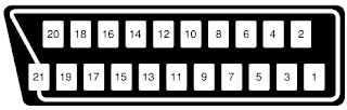
21-Pin Euro-scart pin details.
1. Audio right output
2. Audio right input
3. Audio left output
4. Common earth for audio
5. Earth for blue
6. Audio left input
7. Blue input
8. Audio-video control
9. Earth for green
10. Not used
11. Green input
12. Not used
13. Earth for red
14. Not used
15. Red input
16. Red/Green/Blue control
17. Earth for video
18. Earth for video
19. VIDEO output
20. VIDEO input
21. Common earth


Service mode function
All required adjustments for servicing this TV set, may be done in “Service Mode”, except G2 and FOCUS.
To access the service mode
1. Turn the receiver on and ensure that it is tuned into a test pattern.
2. Turn the receiver off using the mains switch.
3. Press the volume down and channel up buttons together.
4. Continue pressing the volume down and channel up buttons while turning the mains on using the mains switch. 
5. Keep pressing the volume down and channel up buttons until the picture appears.
6. When <<SHARPX X VXX.XX>> appears on the screen, release the two buttons.
7. The receiver is now in the service mode.
To move between the various service mode functions, use the channel up and down buttons. 
Use the volume buttons to change the data to the desired value. 
The data will be stored automatically when exiting the service mode. 
To exit the service mode press the standby button on the remote control or turn the receiver off with the mains switch.

Adjustments and data list
Heading:
OSD
Function
Description:
This is what will appear on the screen when at this position
This is the description of the mode’s function.
Range
Initial
Default
FIX/ADJ
This is the range of values that can be entered while in this mode.
This is the initial value, i.e. just after changing the NVM.
This is the recommended default value for this mode
If this is ADJ, then it may be necessary to adjust this value away from the default.

SCREEN ADJUSTMENTS
G2 Adjustment
1. Enter the service mode.
2. Use the channel up or channel down buttons to enter the << BLUE-BACK >> function.
3. Set this to << BLUE-BACK: 0 >>, i.e. blue background is turned off.
4. Turn the set off at the mains.
5. Turn the set back on.
6. Set the picture control settings to normal.
7. Select the SCART input by pressing the TV/SCART button on the remote control. Do not connect an input to the SCART socket. A blank raster will appear.
8. Connect an oscilloscope to TP851 on the CRT PWB. The waveform should be displayed.
9. Adjust the G2 control (screen voltage) so that the peak of this waveform is 3.0V +/-0.1V above the zero volt line.
10. Enter the service mode.
11. Turn the blue background function back on again - set << BLUE-BACK: 1 >>.
12. Turn off the receiver using the mains button.
13. The G2 adjustment is now complete.
Focus Adjustment.
1. Receive a monoscope pattern signal at a level of 60 to 80 dBV.
2. Set the picture settings to normal.
3. Adjust the focus potentiometer to obtain maximum definition.
AGC adjustment.
1. Tune the receiver into a colour bar signal on channel E-12.
2. Set the RF generator to an output signal strength of 57dBV (+/-1dBV) –50 Ohms unbalanced.
3. Connect an oscilloscope to TP201. TP201 is one end of R201.
4. Enter the service mode.
5. Use the channel up and channel down buttons to enter the AGC mode.
6. By using the volume up and the volume down buttons, adjust the AGC until the voltage on TP201 drops by 0.1V
to 0.3V below its maximum value.
7. Change the input signal strength to 66-70dBV and make sure that there is no noise apparent in the picture.
8. Turn the receiver off at the mains, this will exit the service mode and store the adjustment.
Geometry adjustment
1.Tune the set into a Philips test pattern.
2.Enter the service mode.
3.Use the channel up or channel down buttons to enter the desired mode.
4.Use the volume buttons to achieve correct setting.
5.When adjustments are complete, use the standby button to turn off the set. The adjustment values will be stored at this point.
V-LIN
Adjust the vertical linearity control so that the picture at the center of the screen.
V-AMP
Adjust the vertical amplitude control so that the picture over scans.
V-CENT
Adjust the vertical centering control so that the picture is centered.
H-CENT
Adjust the horizontal centring control so that the picture is centred.
colour adjustment.
This adjustment must be done after warming up the unit for 30 minutes or longer with a beam current over 700 µA.
The red value «DRI-RS» should be fixed to 42. (Refer to “How to access service mode”).
«DRI-GS» adjustment alters “Y” co-ordinate.
«DRI-BS» adjustment alters “X” and “Y” co-ordinates.
METHOD 1 (using the signal generator, varying the picture signal)
Adjust G2.
2. Input a white pattern with burst signal from SCART.
3. Position the colorimeter in the centre of screen.
4. Adjusting input signal level, select a luminance of 70 nits.
5. Operate again in “service mode“ and select «DRI-GS» and/or «DRI-BS» locations to obtain colour co-ordinates:
6. Re-set the TV with the mains switch button to store the adjustment and exit service mode.
7.
Check color co-ordinates “X” and “Y” at 20 a 120 Nits. It may be necessary to repeat the same procedure to obtain the above values.
METHOD 2 (using the signal generator, with a fixed picture signal)
1. Adjust G2.
2. Tune a white pattern with burst signal.
3. Operate in “service mode”:
4. Using «SUB-CON», select a luminance of 70 nits.
5. Operate again in “service mode“ and select «DRI-GS» and/or «DRI-BS» locations to obtain colour co-ordinates.
6. Select «SUB-CON». Return data to “63”.
7. Re-set the TV with the mains switch button to store the adjustment and exit service mode.
8.
Check colour co-ordinates “X” and “Y” at 20 a 120 Nits. It may be necessary to repeat the same procedure to obtain the above values.
LED flashing code
The led indicates the power mode, occurred I2C error and On timer
- Current power mode
- I2C Errors
- On timer
If in STANDBY mode and ON timer in-active then switch LED off.
- If in STANDBY and ON timer active set LED to blinking, (switch on and off at 1 Hz with a 50 % duty cycle).
- If in POWER-ON mode, switch LED on.
- If an I2C error occurred, let the LED blink at 1 Hz, 50 % duty cycle.
For the blinking times see the Table below.
Only when an I2C error occurs for a number of times, or for a number of seconds, the I2C error is handled by the system (that is ,only then the set will go to standby, the led starts blinking).
PIN configuration of TDA935X- [SDIP64]
Information:TDA9381 (IC801)
The function of pin 20, 28, 29, 31, 32, 35 and 44 is dependent on the IC version (mono intercarrier FM demodulator / QSS IF amplifier and East-West output or not) and on some software control bits.
The vertical guard function can be controlled via pin 49 or pin 50. The selection is made by means of the IVG bit in sub-address 2BH.
When additional (external) selectivity is required for FM-PLL system pin 32 can be used as sound IF input. This function is selected by means of SIF bit in sub-address 28H.
The reference output signal is only available for the CMB1/CMB0 setting of 0/1. For the other settings this pin is a switch output.
TEA1507-SMPS control IC details
SCHEMATIC AND TROUBLESHOOTING TABLES
Troubleshooting tables

Friday, May 29, 2020

Philips LX8200SA 22S AV System-Home Theater Audio-How to reprogram DVD version matrix, How to check the version matrix and firmware version number, power amplifier schematic

For repair information on the SD4.00SA DVD Module, refer to Service Manual "DVD Module SD-4.00SA_CH - 3122 785 12480".
For repair information on the Subwoofer SW8000SA/00S, refer to Service Manual "SW8000SA/00S/01S/17S - 3139 785 30099"
Output power (6 ohm, 1kHz, 10% THD) L & R, Center, Surround : 40W RMS / channel
Amplifier Frequency Response (-3dB) : 250Hz-32kHz
SOUND: JAZZ, ROCK, DIGITAL, CLASSIC [DRAMA, ACTION, SCI-FI, CONCERT]
[.....] Sound effect available when playing a DVD/VCD disc.
Input sensitivity
Aux in (at 1kHz) : 880mV ± 3dB
TV in (at 1kHz) : 350mV ± 3dB
Output sensitivity
Line out (Left/Right) : 0.6V ± 2dB at 100 kohm
Center out (Vol. Max.) : 500mV ± 2dB at 47 kohm
Subwoofer out (Vol. Max.) : 0.76V ± 2dB at 47 kohm
Headphone output at 32 ohm : 660mV ± 2dB (Vol. Max.)
Digital in : IEC 60958
Digital out : SPDIF Coaxial
Reprogramming of DVD version matrix [Only a qualified service person should do the reprogramming.]
After replacement/repair, the customer settings and also the region code may be lost.
Reprogramming will put the set back in the state in which it has left the factory, i.e. with the default settings and the allowed region code.
Reprogramming is done by the Remote Control.
Complete version matrix to be enter is
'PLAY 159 XXX XXX XX PLAY'
1) Ensure no disc is loaded in the tray.
2) Set the Remote Control to
DISC source.
3) Press <PLAY> followed by numerical keys <1> <5> <9>
Remark: Top left hand corner of the TV screen will display "X" for all these 4 keys that you have pressed.
4) Press now the following numerical keys (8 digits version matrix):
Remark: Nothing will be displayed on the TV screen for all these 8 digits that you have pressed.
for LX8200SA/22S : <2> <2> <2> <0> <3> <7> <0> <8>
5) Press <PLAY> again.
Caution: Wait for about 3 seconds for the set to reset to the required setting.
The TV screen will turn blue follow by a loud sound at the speaker output.
6) Disconnect mains to ensure proper reset.
How to check the version matrix and the software version number of the set:
1) Power up the set and select
DISC source.
2) Press <SYSTEM MENU> on the Remote Control to enter the User Preference Manual (UPM),
follow by pressing the following key:
-
<Cursor Down> key 4 times
-
<Cursor Right> key 1 time
-
<Cursor Down> key 4 times
3) Message "(C)PHILIPS 01- 02 5580 W.WW.WW ...... PXXXXXXXX Y.YY.Y" will be displayed
on the TV screen:
W.WW.WW
- indicate the BEA software version number
PXXXXXXXX - indicate the version matrix programmed
Y.YY.Y
- indicate the FEA (servo) software version number
4) Press <SYSTEM MENU> on the Remote control to exit.
Setting the TV system default
Press <SYSTEM MENU> on the Remote Control to enter the User Preference Manual (UPM).
2) From the User Preference Manual on the TV screen, select TV SYSTEM to change the TV system default
accordingly as shown in the table below:
Version
/21R
/21S
/22S
/30S
/33S
/37S
Region
Region 3
Region 4
Region 2
Region 4
Region 3
Region 1
TV system default
AUTO
NTSC
PAL
AUTO
AUTO
NTSC

3) Press <SYSTEM MENU> on the Remote control to exit.
Power amplifier board circuit diagram