Sharp SEJB21HM10F00 SECAM B/G, L/L’ - PAL B/G SYSTEM COLOR TELEVISION, service mode, service mode adjustments, troubleshooting,
full circuit diagram and more
The chassis in this receiver is partially hot. Use an isolation
transformer between the line cord plug and power receptacle, when servicing
this chassis.
To prevent electric shock, do not remove cover. No user-serviceable parts inside.
To prevent electric shock, do not remove cover. No user-serviceable parts inside.
It is important that the static charge is removed from the high
voltage system when carrying out work on the receiver. This can be achieved by
connecting a 10K resistor (with a suitably insulated lead) from the CRT cavity
connector to the CRT ground tag. This must be carried out with the AC supply
disconnected from the receiver.
This receiver is designed to keep any x-ray emission to an
absolute minimum. Some fault conditions and servicing procedures may produce
potentially hazardous x-ray radiation levels. This is a problem when in close
proximity to the receiver for long periods of time. To reduce any risks
associated with this, observe the following precautions:
1. When undertaking any servicing on this chassis, DO NOT increase
the EHT to more than 30.5 KV, (at a instantaneous beam current of 1300)
2. Ensure that during normal operation the EHT does not exceed 25.0 KV +/- 1.5KV (at a beam current of 1100.) This level has been preset in the factory. Always check that this level has not been exceeded after carrying out any repair on the receiver.
3. DO NOT replace the CRT with any other type than that specified in the parts listing as this may cause excessive x-ray radiation.
White Level
Set the brightness control, with no signal connected, so that
the CRT cathode current is 600mA. The maximum correction applied to each
cathode current to achieve a screen temperature of 8900 degrees K-20 MPCD
should not exceed 15% of its original value.
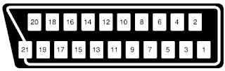
21-Pin Euro-scart pin details.
1. Audio right output
2. Audio right input
3. Audio left output
4. Common earth for audio
5. Earth for blue
6. Audio left input
7. Blue input
2. Audio right input
3. Audio left output
4. Common earth for audio
5. Earth for blue
6. Audio left input
7. Blue input
8. Audio-video control
9. Earth for green
10. Not used
11. Green input
12. Not used
13. Earth for red
14. Not used
9. Earth for green
10. Not used
11. Green input
12. Not used
13. Earth for red
14. Not used
15. Red input
16. Red/Green/Blue control
17. Earth for video
16. Red/Green/Blue control
17. Earth for video
18. Earth for video
19. VIDEO output
20. VIDEO input
21. Common earth
19. VIDEO output
20. VIDEO input
21. Common earth

Service mode function
All required adjustments for servicing this TV set, may be done
in “Service Mode”, except G2 and FOCUS.
To access the service mode
1.
Turn the receiver on and ensure that it is tuned into a test pattern.
2. Turn the receiver off using the mains switch.
3. Press the volume down and channel up buttons together.
4. Continue pressing the volume down and channel up buttons
while turning the mains on using the mains switch.
5. Keep pressing the volume down and channel up buttons until the picture
appears.
6. When <<SHARPX X VXX.XX>> appears on the screen, release the two
buttons.
7. The receiver is now in the service mode.
To move between the various service mode functions, use the
channel up and down buttons.
Use the volume buttons to change the data to the desired value.
The data will be stored automatically when exiting the service mode.
To exit
the service mode press the standby button on the remote control or turn the
receiver off with the mains switch.

Adjustments and data list
Heading:
OSD Function |
Description:
This is what will appear on the screen when at this position This is the description of the mode’s function. |
Range
Initial Default FIX/ADJ |
This
is the range of values that can be entered while in this mode.
This is the initial value, i.e. just after changing the NVM. This is the recommended default value for this mode If this is ADJ, then it may be necessary to adjust this value away from the default. |

SCREEN ADJUSTMENTS
G2 Adjustment
1. Enter the service mode.
2. Use the channel up or channel down buttons to enter the << BLUE-BACK >> function.
3. Set this to << BLUE-BACK: 0 >>, i.e. blue background is turned off.
4. Turn the set off at the mains.
5. Turn the set back on.
6. Set the picture control settings to normal.
7. Select the SCART input by pressing the TV/SCART button on the remote control. Do not connect an input to the SCART socket. A blank raster will appear.
8. Connect an oscilloscope to TP851 on the CRT PWB. The waveform should be displayed.
9. Adjust the G2 control (screen voltage) so that the peak of this waveform is 3.0V +/-0.1V above the zero volt line.
10. Enter the service mode.
11. Turn the blue background function back on again - set << BLUE-BACK: 1 >>.
12. Turn off the receiver using the mains button.
13. The G2 adjustment is now complete.
Focus Adjustment.
1. Receive a monoscope pattern signal at a level of 60 to 80 dBV.
2. Set the picture settings to normal.
3. Adjust the focus potentiometer to obtain maximum definition.
2. Set the picture settings to normal.
3. Adjust the focus potentiometer to obtain maximum definition.
AGC adjustment.
1. Tune the receiver into a colour bar signal on channel E-12.
2. Set the RF generator to an output signal strength of 57dBV (+/-1dBV) –50 Ohms unbalanced.
3. Connect an oscilloscope to TP201. TP201 is one end of R201.
4. Enter the service mode.
5. Use the channel up and channel down buttons to enter the AGC mode.
6. By using the volume up and the volume down buttons, adjust the AGC until the voltage on TP201 drops by 0.1V
to 0.3V below its maximum value.
7. Change the input signal strength to 66-70dBV and make sure that there is no noise apparent in the picture.
8. Turn the receiver off at the mains, this will exit the service mode and store the adjustment.
Geometry adjustment
1.Tune the set into a Philips test pattern.
2.Enter the service mode.
3.Use the channel up or channel down buttons to enter the desired mode.
4.Use the volume buttons to achieve correct setting.
5.When adjustments are complete, use the standby button to turn off the set. The adjustment values will be stored at this point.
2.Enter the service mode.
3.Use the channel up or channel down buttons to enter the desired mode.
4.Use the volume buttons to achieve correct setting.
5.When adjustments are complete, use the standby button to turn off the set. The adjustment values will be stored at this point.
V-LIN
Adjust the vertical linearity control so that the picture at the center of the screen.
Adjust the vertical linearity control so that the picture at the center of the screen.
V-AMP
Adjust the vertical amplitude control so that the picture over scans.
Adjust the vertical amplitude control so that the picture over scans.
V-CENT
Adjust the vertical centering control so that the picture is centered.
Adjust the vertical centering control so that the picture is centered.
H-CENT
Adjust the horizontal centring control so that the picture is centred.
Adjust the horizontal centring control so that the picture is centred.
colour adjustment.
This adjustment must be done after warming up the unit for 30
minutes or longer with a beam current over 700 µA.
The red value «DRI-RS» should be fixed to 42. (Refer to “How to access service mode”).
«DRI-GS» adjustment alters “Y” co-ordinate.
«DRI-BS» adjustment alters “X” and “Y” co-ordinates.
The red value «DRI-RS» should be fixed to 42. (Refer to “How to access service mode”).
«DRI-GS» adjustment alters “Y” co-ordinate.
«DRI-BS» adjustment alters “X” and “Y” co-ordinates.
METHOD 1 (using the signal
generator, varying the picture signal)
Adjust G2.
2. Input a white pattern with burst signal from SCART.
3. Position the colorimeter in the centre of screen.
4. Adjusting input signal level, select a luminance of 70 nits.
5. Operate again in “service mode“ and select «DRI-GS» and/or «DRI-BS» locations to obtain colour co-ordinates:
2. Input a white pattern with burst signal from SCART.
3. Position the colorimeter in the centre of screen.
4. Adjusting input signal level, select a luminance of 70 nits.
5. Operate again in “service mode“ and select «DRI-GS» and/or «DRI-BS» locations to obtain colour co-ordinates:
6. Re-set the TV with the mains switch button to store the
adjustment and exit service mode.
7. Check color co-ordinates “X” and “Y” at 20 a 120 Nits. It may be necessary to repeat the same procedure to obtain the above values.
7. Check color co-ordinates “X” and “Y” at 20 a 120 Nits. It may be necessary to repeat the same procedure to obtain the above values.
METHOD 2 (using the signal
generator, with a fixed picture signal)
1. Adjust G2.
2. Tune a white pattern with burst signal.
3. Operate in “service mode”:
4. Using «SUB-CON», select a luminance of 70 nits.
5. Operate again in “service mode“ and select «DRI-GS» and/or «DRI-BS» locations to obtain colour co-ordinates.
2. Tune a white pattern with burst signal.
3. Operate in “service mode”:
4. Using «SUB-CON», select a luminance of 70 nits.
5. Operate again in “service mode“ and select «DRI-GS» and/or «DRI-BS» locations to obtain colour co-ordinates.
6. Select «SUB-CON». Return data to “63”.
7. Re-set the TV with the mains switch button to store the adjustment and exit service mode.
8. Check colour co-ordinates “X” and “Y” at 20 a 120 Nits. It may be necessary to repeat the same procedure to obtain the above values.
7. Re-set the TV with the mains switch button to store the adjustment and exit service mode.
8. Check colour co-ordinates “X” and “Y” at 20 a 120 Nits. It may be necessary to repeat the same procedure to obtain the above values.
LED flashing code
The led indicates the power mode, occurred I2C error and On timer
- Current power mode
- I2C Errors
- On timer
- I2C Errors
- On timer
If in STANDBY mode and ON timer in-active then switch LED off.
- If in STANDBY and ON timer active set LED to blinking, (switch on and off at 1 Hz with a 50 % duty cycle).
- If in POWER-ON mode, switch LED on.
- If an I2C error occurred, let the LED blink at 1 Hz, 50 % duty cycle.
For the blinking times see the Table below.
- If in STANDBY and ON timer active set LED to blinking, (switch on and off at 1 Hz with a 50 % duty cycle).
- If in POWER-ON mode, switch LED on.
- If an I2C error occurred, let the LED blink at 1 Hz, 50 % duty cycle.
For the blinking times see the Table below.
Only when an I2C error occurs for a number of times, or for a
number of seconds, the I2C error is handled by the system (that is ,only then
the set will go to standby, the led starts blinking).

PIN configuration of TDA935X- [SDIP64]

Information:TDA9381 (IC801)
The function of pin 20, 28, 29, 31, 32, 35 and 44 is dependent on
the IC version (mono intercarrier FM demodulator / QSS IF amplifier and
East-West output or not) and on some software control bits.
The vertical guard function can be controlled via pin 49 or pin
50. The selection is made by means of the IVG bit in sub-address 2BH.
When additional (external) selectivity is required for FM-PLL
system pin 32 can be used as sound IF input. This function is selected by means
of SIF bit in sub-address 28H.
The reference output signal is only available for the CMB1/CMB0
setting of 0/1. For the other settings this pin is a switch output.

TEA1507-SMPS control IC details

SCHEMATIC AND TROUBLESHOOTING TABLES


Troubleshooting tables


No comments:
Post a Comment