Saturday, June 29, 2013

MITSUBISHI LASERVUE - HOW TO REMOVE LIGHT SOURCE ASSEMBLY & INSTALLATION


LIGHT SOURCE ASSEMBLY REMOVAL
  1. Prior to removing the Light Source Assembly, AC power must be removed. AC power must not be re-applied until all covers are replaced back into their original position, all screws are in place.
  2. The Fiber Optic Cable is sensitive to excessive pulling, bending and crushing forces. Do not bend cable more sharply than a bend radius of 100mm (4 inches). Do not pull on the cable. Do not crush the cable or allow it to kink. Do not allow the end of the fiber optic cable to make contact with any surface including fingers.
  • Remove the Electrical Chassis. [Described one among the previous posts here]]
  • Loosen the Tape used to secure the Fiber Optic Cable to the back wall.
  • Disconnect all electrical connectors from the bottom of the Light Source Assembly.
  • Remove 6 screws (a).
  • Note: the Hinges at the lower left and right side will now hold The Light Source Assembly.
  • Holding the Light Source Assembly with both hands at the bottom, pull the entire Light Source straight back slightly within the Hinge slots.
  • Carefully tilt back the Light Source Assembly from the top and secure in place using the support arms.
  • Disconnect the four 8mm Fiber Optic Cable Connectors from the Light Source Assembly. Caution: Never loosen or tighten the chuck nuts used to attach the cable to the connectors.
  • After disconnecting the Fiber Optic Cable, temporarily secure it to the back wall to prevent damage.
  • Use the End Caps and Special Yellow Tape supplied with the replacement Light Source or Optical Engine to cover and protect the ends of the Fiber Optic Cables and Laser Modules until reassembly.
  • To remove the Light Source Assembly, tilt it back up and store the support arms. Then while supporting the assembly, remove the eight screws (a) and lift the assembly out.

Light Source Assembly Installation
  • To install the Light Source Assembly, reverse the removal procedure.
  • Use an 8mm open end torque wrench to tighten the Fiber Optic Cable Connectors to 0.2N • m (+/- 3%).  NOTE: When a Light Source Assembly or Light Engine is ordered, an 8mm open end torque wrench will be supplied on loan from the Parts Department.
  • Prior to applying AC power re-assemble the set.
If the Light Source Assembly has been replaced, perform the following data transfer procedures: Reset SENSOR-RGB Data.
  1. Plug in the TV and allow it to boot-up, but do not turn it On (Standby condition).
  2. On the front panel, press and hold the <MENU> and <CHANNEL S> buttons at the same time about 5 seconds until the STATUS LED lights green for 3 seconds.
  • Memorize SENSOR-RGB
  1. Turn the TV on and allow it to warm up for 5 minutes.
  2. Press the <MENU> button on the remote control. The Customer Menu will appear.
  3. Press the <2-4-5-7> buttons. The Service Menu will appear.
  4. Press the <0> button. The Data Selection Menu will appear.
  5. Use the <TS> buttons to select “MEMORIZE SENSOR-RGB” and press <ENTER>. A green square will appear in the on screen display indicating the memorization process was successful. If a red square appears, repeat the Reset SENSOR-RGB Data and Memorize SENSOR-RGB Data procedures.
  6. Press <EXIT> to quit.

FORD MONDEO - HOW TO CHECK ANTI-THEFT ALARM SYSTEM


ANTI-THEFT ALARM SYSTEM
  • The system includes a start inhibitor circuit, which makes it impossible to start the engine with the system armed.
  • The movement sensors consist of two ultrasonic units, located in the “B” pillars, incorporating transmitters and receivers (see illustrations). The receivers check that the echo frequency matches the original frequency. If there is any significant difference, the system triggers the alarm.

  • The system module is located on a bracket beneath the right-hand side of the fascia. The set and reset switches are located in a housing by the lock barrel holder in the doors, tailgate or boot lid.
  • To allow temporary opening of the tailgate or boot lid, an inhibit switch is fitted to the lock barrel. This suppresses the alarm system until the tailgate or boot lid is closed again.
  • Where remote central locking is fitted, an infra-red receiver is located on the exterior door handle (see illustration). Note that excessive heat can destroy this receiver; therefore, it should be covered with aluminum tape if (for instance) a paint-drying heat process is to be used.
  • The alarm system is fitted with its own horn. On Hatchback and Saloon models, it is located on the left-hand side of the luggage compartment; on Estate models, it is located on the right-hand side of the luggage compartment (see illustration).
  • The alarm system incorporates a self-test function, which can be activated by operating the bonnet switch or one of the lock position switches eight times within 10 seconds. During the check, the horn or buzzer issues acoustic signals, which should occur every time a door, bonnet or tailgate is opened. If the doors are double-locked, the signal will occur when something is moved within the passenger compartment. A more comprehensive test can be made using the Ford FDS 2000 diagnostic tester.
  • The door lock switches associated with the alarm system are located behind the door trim panels (see illustration).

Friday, June 28, 2013

AKAI 21CTU91BC - HOW TO ENTER SERVICE MODE - MAIN POWER SUPPLY [SMPS] SCHEMATIC - MEMORY IC REPLACEMENT - LOGO EDIT - Zoom Adjust - FACTORY DEFAULT DATA TABLE - Universal Remote Control Set-up Codes


SERVICE MODE [FACTORY MODE]
  • To enter BUS control mode, Press “TEST” key on the Remote control unit of factory.
  1. Customer remote control press "MENU" key behind in a row press"6""4""8""3"
  2. Choose a "SETUP SELECT" options in "M2" menu, one by one in order press the numerical key"6, 4, 8 and 3",  press "MUTE" key again can depend on this get into "M3"~"M9" of design menu, general factory the production doesn't need to carry on M 3~ adjustments of M9.
  3. In "M0"~under"M9" appearance press” CALL” the key can get into "M" appearance.
  4. At “M” under the appearance press “-/-“ the key can get into “BUS OPEN” appearance, at “BUS OPEN under, press-/-“ the key recover factory appearance.
REMOTE CONTROL KEYS
FACTORY DATA SETTINGS [DEFAULT]
{CLICK ON TABLES TO ZOOM IN}
LOGO EDIT
This software LOGO is a pair of pleased words and customer to edit 2 kinds, at the M_MODE; long press [P.P] the key can get into a pair of pleased words editor appearance.
  • Press [1]/[2] keys:  The LOGO perpendicular position adjust, [1] adjusts upward, [2] get down adjustment;
  • Press [3]/[4] keys: The LOGO level position adjusts, [3] is to the left adjustment, [4] and rightwards adjusts; 
  • Press [REVIEW] key: Withdraw LOGO editor appearance, the LOGO information remembers EEPROM and return to M_MODE;
  • Press again [MENU] the key can get into and can edit LOGO appearance.
  1. Press [1]/[2] keys:  The  LOGO  perpendicular position adjust, [1] adjusts upward, [2] get down adjustment;
  2. Press [3]/[4] keys: The LOGO level position adjusts, [3] is to the left adjustment, [4] and rightwards adjusts; 
  3. Press [5]/[6] keys: The color choice of the LOGO character list, [5] change the first color, [6] change the second color;
  4. Press [7]/[8] keys: The LOGO character list size adjusts, [7] change the first size, [8] and regulate the second size;
  5. Press [0] keys: Delete the letter of alphabet of importation.
  • Press [(]/[(] key: The LOGO character list choose (0~9;A~Z;a~z; ":.+-*/@", SPACE);
  • Press [(]/[(]key: Move cursor;
  • Press [REVIEW]key: Withdraw LOGO editor appearance, the LOGO information remembers EEPROM and return to M_MODE.
The ZOOM adjusts.
At the M_MODE, press [ZOOM] key: Press when screen showed "ZOOM" or"16:9"[VOL+]/[VOL-] the key regulated ZOOM/16:9 of field.
SMPS SCHEMATIC DIAGRAM

For Universal remote control set-up codes to Akai, either see the previous post or Click Here.

AKAI 21CT32FSR - HOW TO ENTER SERVICE MODE - +B ADJUSTMENT - Factory Settings - Universal Remote Control Set-up Codes - {Click on Pictures to Zoom In}


+B ADJUSTMENT
  • Receive standard color pattern RF signal, or receive a good transmission signal, and  set picture to “Standard Mode”.
  • Adjust VR501 to get +B (VD631 -) voltage =110 V
IIC BUS CONTROL ADJUSTMENTS & ENTER AND EXIT SERVICE MODE
  • For remote controller of factory.
Continuous push [test] key on remote controller, the TV mode will change as follow:
NORMAL => M => BUS OPEN [you can select “M” ( factory mode ) or “normal” mode.]
  • For remote controller of user
Push [menu] key, àdisplay picture manual à  push digital key 8500 à display M.
Push [standby] key , exit factory mode and TV will be standby.
GEOMETRICAL ADJUSTMENT -MENU-8
Receive standard Crosshatch pattern signal for PAL system.
  • Adjust VSLOPE value to the horizontal line just appear from half bottom shadow. 
  • Adjust VSHIFT value the center horizontal line corresponds to CRT vertical center.
  • Adjust Vamp value to get 90% of vertical picture contents would be displayed on CRT.
  • Adjust HSHIFT value to get the picture horizontal center correspond to CRT horizontal center.
  • Receive standard Crosshatch pattern signal for NTSC system, and again adjust.
AGC TOP ADJUSTMENT - MENU-7
Receive 60dBu (1mv)VH color bar signal adjust AGC value voltage from high to low to   picture noise reduce gradually to be just disappeared.
CRT CUT-OFF, WHITE  BALANCE & SUB-BRIGHT ADJUSTMENT
Receive gray and white 2 steps signal.
CRT cut off adjustment
  • Push [P+][P-] key to select “SC”, push [V+][V-] key then automatically vertical scan will be stopped.
  • Adjust SCREEN control on Flyback transformer to get the darkest single horizontal line (red, green,or blue, sometimes shows more yellow, more purple or more white).
  • Push [V+][V-] key again, vertical scan work repeat. 
  •  Select RD/BD menu.
  • Adjust RD/BD to get color temperature as x=281, y=311.
Sub-brightness adjustment (use stair case signal)
  • Select SB MENU.
  • Adjust SB to get the darkest step being on or off.
SHIP MODE - MENU-6
  • Select “SHIPMODE”, push [V+][V-]key may be shipped.
  • Note: Any increase the screens of FBT current, the darking single ought   no flyback line, AV state.
21" DEFAULT SETTINGS [IIC BUS CONTROL NTDA93X1]
Factory default settings

TEXT DEF : TXT_def = 0: Pan_Euro + Cyrillic   
  1. Farsi English + French + Turkish    
  2. Arabic + English + French + Turkish
  3. UKRAINIAN
Attention:
When TXT_def=0, will appear" the TXT LANGUAGE" in the customer Setup menu, press V+/ V- key," the TXT LANGUAGE" will appear the following circulation: W- TR-> EAST1-> EAST2-> W- TR
  • The W- TR diagram text includes the following language:
 English German Swedish/Fin/Dan/Hungarian Italian French Spanish/Portuguese Turkish
  • The EAST1 diagram text includes the following language:
Polish German Estonian  Slovenian Czech/Slovak Rumanian
  • The EAST2 diagram text includes the following language:
Polish German Swedish/Fin/Dan/Hungarian, Lettish Russian Slovenian Czech/Slovak Estonian.
  • Make use of 4 color keys of the remote control; browse 4 pages of the enactment quickly, namely index function.
  • The TV/ AV sets the saving key for the index.
  • While using this function," the TXT LIST" establishes for" ON" in the customer menu.
Example: if want to use the color key of the red quickly 230 pages of enter the diagram text:
The sequence press" TEXT"," red key","2","3","0" on the remote control," TV/ AV"
Switch on the hour appearance constitution
[0]  Connect the AC power, enter to need the machine appearance automatically
[1]  Connect the AC power, automatically switch on appearance
[2]  Connect the AC power, if shut down the appearance as the diagram text appearance, enter the diagram text appearance automatically.
UNIVERSAL REMOTE CONTROL SET-UP CODES FOR AKAI
GE UNIVERSAL REMOTE CONTROL: 0105 0002 0077 0254
RCA RCR 311W: 1221, 1001, 1046, 1078, 1203, 1204
RCA RCR 312W: 10812, 11675, 10060, 10702, 10030, 10672
Others: 1134 1052 1204 1201 1157 1203 1132 1075 1061 1003 1210 1231 1019 1054 1051 1203 1077 1014 1314 1007 1172 1031 1072 1274 1160 1285 1162 1035 1349 1433 1243 1012 1140 1190 1144 1091 1141 1288 1184 1109 1351 1311 1341 1342 1211

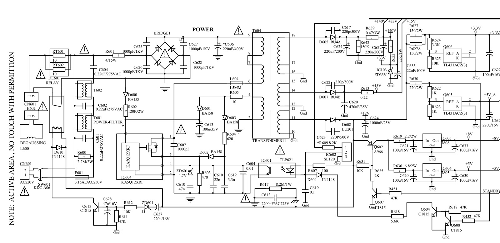
AKIRA C-21FS9R - Using ICs NJM2192A – TDA9859 – TDA8944 – TDA4893 – TDA93XX / N2 [Philips UOC] – 24C08 – TDAA8390 & KA5Q12XRF[STR] SCHEMATIC DIAGRAM


PWB
SCHEMATIC DIAGRAM [POWER SMPS SECTION]
SCHEMATIC DIAGRAM [FULL]
{CLICK ON PICTURES TO ZOOM IN}
DEFAULT DATA VALUES

Thursday, June 27, 2013

LASERVUE - MITSUBISHI - V-40 CHASSIS L65-A90 - DISASSEMBLE PROCEDURE {Click on Pictures to Zoom In}


DISASSEMBLE PROCEDURE
Product Transpiration
This receiver is provided with “Transportation Screws” to be used to secure the screen assembly during transportation. Prior to moving this set, remove AC power and install the 4 transportation screws as shown below.
Before Moving the TV Receiver install the Transportation Screws
  • Remove AC power.
  • Raise Screw Cover to access screw opening.
  • Use 5mm allen wrench to install Transportation Screw.
  • Repeat at the 4 locations (a) shown.
After Moving the TV Receiver, remove the Transportation Screws
  • Do NOT apply AC power.
  • Use 5mm allen wrench to remove Transportation Screw.
  • Slide Screw Cover back down over the opening.
  • Repeat at the 4 locations (a) shown above.
NOTE: Transportation Screws are the property of the customer. Retain the screws with the set for future use.  Suggestion: Place them in a plastic bag and attach it to the back of the set.
Removable Pedestal:  This receiver comes equipped with a Pedestal that must be removed to install either the optional wall mount kit, model LWM-65, or the optional stand, model LFB-65. The TV receiver will not properly stand upright on its own without the Pedestal.  When transporting, disassembling, and/or repackaging the receiver, the Pedestal must be re-installed using the eighteen screws in the locations shown below.
Disassembly beyond what is shown here is not recommended. For repairs requiring further disassembly, contact MDEA Mitsubishi Service Centre.
The Screen Assembly is unique to this product. As such, it is not considered to be a field serviceable item.
  • For repairs related to any part of the screen or screen assembly, contact the Service Centre.
  • Do not allow the rear of the screen to come into contact with any other surface including cleaning cloths or fingers. Remove dust or other debris by blowing with a dry air source.
  • For optional wall mount or stand mount installations, prior to disassembly see Removable Pedestal.
UPPER CABINET BACK REMOVAL
  1. Remove the six screws (a).
  2. Remove the two machine screws (b).
  3. Remove the Upper Cabinet Back.
  4. To re-install, reverse steps 1~2.
ELECTRICAL CHASSIS REMOVAL
  1. Disconnect all cables from the Electrical Chassis.
  2. Remove five screws (a).
  3. Remove two screws (b).
  4. Carefully remove the Electrical Chassis from the Cabinet.
  5. To re-install, reverse steps 1~3.
POWER SUPPLY SHIELD REMOVAL
  1. Remove five screws (a)
  2. Lift the Power Supply Shield from the Chassis.
  3. Reverse the removal procedure for re-installation.
POWER BOARD REMOVAL
  1. Remove seven screws (a)
  2. Disconnect all cables from the PWB-POWER.
  3. Release Clips (b)
  4. Lift the PWB-POWER from the Chassis.
  5. Reverse the removal procedure to install a new PWB-POWER.
3D-POWER BOARD REMOVAL
  1. Remove two screws (c) from RS-232 connector.
  2. Remove one screw (d) from 3D Emitter Jack.
  3. Remove two screws (e) from PWB-3D.
  4. Disconnect the cable from the PWB-3D.
  5. Lift the PWB-3D from the Chassis.
  6. Reverse the removal procedure to install a new PWB-3D
CHASSIS COVER REMOVAL
  1. Remove Power Supply Shield.
  2. Remove Terminal Escutcheon by removing two screws (a).
  3. Remove two screws (b) from the RS-232 connector on Terminal Panel.
  4. Remove four screws (c) from Terminal Panel.
  5. Remove five screws (d) from around the edge of the Chassis Cover.
  6. Disconnect the cables from the PWBPOWER and PWB-3D.
  7. Lift the Chassis Cover from the Chassis.
  8. Reverse the removal procedure to re-install the Chassis Cover.
MAIN PWB REMOVAL
  1. Remove two antenna nuts (a) from the Terminal Panel.
  2. Remove five screws (b) from the Terminal Panel.
  3. Remove four machine screws (c) from the Terminal Panel.
  4. Remove nine screws (d) from the PWB-MAIN.
  5. Disconnect the cables from the PWB-MAIN.
  6. Lift the PWB-MAIN from the Chassis.
MAIN PWB INSTALLATION
Reverse the removal procedure to install a new PWB-MAIN.  After fully re-assembling the set, perform the following data transfer procedures:
  • Press the <MENU> button on the remote control. The Customer Menu will appear.
  • Press the <2-4-5-7> buttons. The Service Menu will appear.
  • Press the <0> button. The Data Selection Menu will appear.
  • Use the <▲▼> buttons to select “RESTORE ALIGNMENT AND WHITE BALANCE SETTINGS FROM BACKUP” and press <ENTER>. You will automatically exit the Data Selection Menu.
  • Press the <0> button. The Data Selection Menu will appear again..
  • Use the <▲▼> buttons to select “RESTORE KEYSTONE GEOMETRY FROM BACKUP” and press <ENTER>. You will automatically exit the Data Selection Menu.
  • Press <EXIT> to quit.

MITSUBISHI LASERVUE PROJECTION HDTV - HOW TO ENTER SERVICE MODE & ADJUSTMENTS - LED BLINKING CODES - ERROR CODE LOG - ERROR CODES OPERATIONAL CHECK


FRONT PANEL LED INDICATIONS
The front panel LEDs provides an indication of the set’s operation, and the possible cause of a malfunction. There are two front panel LEDs, “Power” and “Status.” The LED display shows the current status or indicates a possible malfunction.  If an abnormal condition is indicated, proceed to the Error Code Operational Check for more specific information.
Power LED [Normal Condition]

Status LED
Condition
Off
Off
Off (Standby)

Fast Blinking Green
Off
Initialization (40 - 60 seconds after set plugged in or System Reset)

Green
Off
Power On

Slow Blinking Green
Off
Power On Timer is set

Abnormal Indications


Off
Yellow
* Temperature high – room hot.
* Laser unit temperature is abnormally high.
* Optical fiber temperature is abnormally high

Off
Blinking Yellow
Cover-back (top/bottom)is open.  Yellow Laser unit is not assembled completely.

Off
Red
* Laser unit failure
* Laser abnormal brightness
* Linear motor failure
* Communication in laser unit failure
Chassis side failure
*Communication with laser micro fail
* Communication with engine fail
* No Lamp-EN, No ASIC-ready
* DVI cable disconnection
Circuit failure (short)

Off
Blinking Red
Fan Stop
(DMD Fan, Fan in laser unit)
ERROR CODE OPERATIONAL CHECK
When the Status LED indicates an abnormal condition, perform the Error Code Operational Check.
To activate, press the front panel INPUT and MENU buttons at the same time and hold for 5 seconds.
The “POWER LED” will then flash denoting a two-digit code.
  • The number of flashes indicates the value of the MSD (tens digit) of the Error Code.
  • The flashing then pauses for approximately 1/2 second.
  • The LED then flashes indicating the value of the LSD (ones digit) of the Error Code.
  • The Error Code is repeated a total of 5 times.
Example: If the Error Code is “23”, the LED will flash two times, pause, and then flash three times.
Note: The TV must be in “Shut Down” and not have been switched Off, to perform the Error Code Operational Check. When the TV is switched Off, the code automatically resets to “12” No Error.
Note: Use the front panel buttons, not the remote control.
Note: If there is no response, the front panel may be locked by a V-Chip setting. To unlock, press and hold MENU for 5 seconds.
LED INDICATOR DIAGNOSIS
Error Codes:  The Error Code designations indicating malfunction, or no malfunction, are listed below:
{CLICK ON PICTURES TO ZOOM IN}
Error Code 19: To reset the SENSOR-RGB Data, first perform the Un-Lock procedure. Then with the set Off (Standby) press MENU and Ch Up for 5 seconds until the STATUS LED turns green for 3 seconds. After operation is restored, perform the MEMORIZE SENSOR-RGB.
Lock out:  The receiver is locked, and cannot be powered ON even after reset.  After correcting the cause, re-boot the TV and un-lock the set by pressing 'Menu' & 'Ch Dn' for 5 seconds, until Red Status LED goes out.
ERROR CODE LOG
The Error Code Log - may be helpful to retrieve the code for an error the occurred in the past.
To access the Error Code Log: Press MENU - 3-5-6-4
Error Code Definitions
  • Page - Current page number
  • Current Time - total hours of operational use.
  • Lamp Time - usage hours when the error occurred.
  • Code - the specific Error Code that occurred.
  • Status - Two types:  OCCURRENCE - when the error occurred.  RECOVERY - when normal operation resumed.
The Error Code Log is intended as a reference tool and is not meant to be used as a final determination of a defective part.
SERVICE MODE
The Service Mode is used for:
  • Test Signal activation - Used for both Electrical and Mechanical Adjustments.
  • Horizontal and vertical position adjustment
  • Keystone, 4:3 and letterbox geometry adjustments.
  • Data transfer (restore and backup).
  • Memorize RGB Sensor.
Activating the Service Mode
  1. Press the “MENU” button on the remote control. The “Customer Menu” will appear.
  2. Press 2-4-5-7. The Service Menu below will appear. If not, press, “EXIT” and repeat steps 1 and 2.
Test Pattern Activation
  • When in the Service Mode, press PLAY <►> to activate the internal test patterns (no indication will be given), then use FAST FORWARD <►►>or REWIND <◄◄>to select the desired Test Pattern.
HORIZONTAL & VERTICAL POSITION ADJUSTMENT
  • Enter the Service Mode (Step 1) .
  • Select the Geometry Test Pattern shown below (Step 2).
  • Select the TVM Function if necessary (Step 3).
  • Use the “VIDEO” button to select the specific adjustment, “1.HVPOS”.

Geometry Test Pattern
  • After selecting the HVPOS adjustment item, use the DIRECTION ▲▼ / ◄► buttons to center the display.
  • If a UP/DOWN <▲▼> button is pressed, the vertical position and VPOS adjustment data changes.
  • If a RIGHT/LEFT <◄►> button is pressed, the horizontal position and HPOS adjustment data changes.
  • Press <ENTER> to save the adjustment data in memory.
  • The display characters go red for approximately one second in this step.
Note: If the circuit adjustment mode is terminated without pressing <ENTER>, changes in adjustment data are not saved.
TSP ALIGNMENT
  • Enter the Service Mode (Step 1) .
  • Select the TSP Test Pattern shown in the following graphic by pressing PLAY <►> two times, then use FAST FORWARD <►►>or REWIND <◄◄>to select the TSP Test Pattern.
  • Select the TVM Function if necessary (Step 3).
  • Use the “VIDEO” button to select the specific adjustment, “2.TSP”.
  • Use the DIRECTION <▲▼> buttons to straighten the horizontal lines, see below.
  • Press <ENTER> to save the adjustment data in memory.  The display characters go red for approximately one second in this step.
TSP Test pattern