Tuesday, August 03, 2021

Philips FX20, FX30, FX50 - Mini Speaker System – How to update the software – schematic diagram – disassemble procedure – Restore default - exploded view


The Software Upgrade way (Update software via USB):
1. Download the Software into the root directory of a USB storage device.
2. Rename the download software file, such as rename the "PCM_MCU_V12.bin"to"PCM_MCU.bin“.
3. Turn on the unit and switch to the USB source.
‐‐>"NO USB" is displayed.
4. Connect the USB storage device to the USB socket on the unit.
‐‐>"MCU UPD"(MCU update) is displayed.
5. Press ">|| " key to start upgrade.
‐‐>"UPGING"(upgrading) is displayed during upgrade. At completion of upgrade, the unit reboots automatically.
6. Delete the "PCM_MCU.bin" in the USB storage device, and repeat step 1>2>3>4>5 > to upgrade MPEG S/W, Rename software file, such as rename "PCM_MPEG_FX20_55_V13.bin"to"PCM_MPEG.bin".
‐‐>"MPEG UPD" is display.

Do not turn off the power or remove the USB storage device when the software update is in progress because you might damage the unit.

The Software Version to view:
1.Turn on the unit and switch to the DISC source.
‐‐>"NO DISC" is displayed.
2. Press "EJECT" key to open the door.
‐‐>"OPEN" is displayed.

3. Press the key STOP > PROG > NEXT in turn on remote control, the VFD will show such as “M1220P13”

Note: When view software version type, VFD can be show below information:

M0820P16

M08 MCU version

20: FX20 model, if this unit is 15/25/30/50/55,mean is FX15/FX25/FX30/FX50/FX55 model

P16: Mpeg version.

Restore default settings:
You can also restore the default settings of the unit.
Turn on the unit, in any source, press and hold both the key >|| and PRESET
on the front panel for more than three seconds. ‐‐>after a while, "RESET OK" is displayed. Then, the unit reboots automatically.

Disassembly

Step 1: Open the top cover. Remove 5 screws on the back panel and 2 screw on the left and right sides, then open the cover from the back panel side.

Step 2: Dismantle the loader. Disconnect the connectors on main board. Remove 2 screws beside the loader. Pull up the loader from the back panel side, the CD door will be separated at the same time.

How to dismantle the player

Step 3: Dismantle the loader bracket. Remove 1 screw on the bracket then remove the bracket directly.

Step 4: Dismantle the front panel. Disconnect the connectors on the main and power board. Release 2 buckles under the bottom plate and 2 screws on the left and right sides.

Step 5: Dismantle the USB board. Remove 2 screws on the board.
Buckles under the bottom plate and 2 screws on the left.
Step 6: Dismantle the IN board. Remove 2 screws on the board.
Step 7: Dismantle the support board. Remove 2 screws on the board.
Step 8: Dismantle the key board. Remove 2 screws on the board and disconnect the connector.

Step 9: Dismantle the front control board. pull out the volume knob. Remove 9 screws on the board.  Release the buckles on the board. Then pull out the board

Step 10: Dismantle the power board. Remove 4 screws on the board.

Step 11: Dismantle the main board. Remove 4 screws on the back panel and 2 screws on the board.

Block diagram for FX20

Circuit diagram – Front control board


Power board schematic


Main board schematic – SP8104WW


Schematic – Main board MCU


Schematic – Main board AMP ST518*2


Exploded view – FX20


Sunday, August 01, 2021

LG 42PJ250-UA, LG42PJ250-UB Plasma TV Service mode, alignments, troubleshooting and Digital audio section schematic


Applicable to all of the PU01A Chassis.

(1) Because this is not a hot chassis, it is not necessary to use an isolation transformer. However, the use of isolation transformer will help protect test instrument.
(2) Adjustment must be done in the correct order.
(3) The adjustment must be performed in the circumstance of 25
degree C ± 5 degree C of temperature and 65 % ± 10 % of relative humidity if there is no specific designation.
(4) The input voltage of the receiver must keep 100 V ~ 240 V, 50 / 60 Hz.
(5) The receiver must be operated for about 5 minutes prior to the adjustment when module is in the circumstance of over 15 degree C.
- In case of keeping module is in the circumstance of 0 degree C, it should be placed in the circumstance of above 15 degree C for 2 hours.
- In case of keeping module is in the circumstance of below -20 degree C, it should be placed in the circumstance of above 15 degree C for 3 hours.
1) Press the POWER ON KEY on Remote control for adjustment.
2) Press the ADJ KEY on Remote control  and enter EZ ADJUST. Select “4. 

WHITE PATTERN” by using (CH +/-) and select “White” by using (VOL +/-)

- Set is activated HEAT run without signal generator in this mode.
- Single colour pattern (RED / BLUE / GREEN) of HEAT RUN MODE uses to check panel.  [If you turn on a still screen more than 20 minutes (Especially digital pattern, cross hatch pattern), an after-image may be occur in the black level part of the screen.]

PCB assembly adjustment method.
* Caution: Set up “RF mode(noise)” after PCB assembly adjustment.
*Download
(1) Execute ISP program “Mstar ISP Utility” and then click “Config” tab.
(2) Set as below, and then click “Auto Detect” and check “OK” message.  If display “Error”, Check connect computer, jig, and set.
(3) Click “Connect” tab. If display “Can’t ”, Check connect computer, jig, and set.

(4) Click “Read” tab, and then load download file(XXXX.bin) by clicking “Read”.

(5) Click “Auto” tab and set as below.
(6) Click “Run”.
(7) After downloading, check “OK” message.


Auto ADC Process (using DFT).

PC (for communication through RS 232C)

UART Baud rate: 115200bps.

Command: aa 00 00 (Start factory mode).Command : ad 00 10 (working Auto ADC).Command : aa 00 90 (End of Auto ADC Process).

Manual ADC Process using Service Remocon.
After enter Service Mode by pushing “ADJ” key, execute “ADC Adjust” by pushing “>” key at “0. ADC CALIBRATION”.

Confirmation.

(1) We confirm whether “0xBF(480i)/0xC8(1080i)” address of EEPROM “0xA2” is “0xAA” or not.

(2) If “0xBF(480i)/0xC8(1080i)” address of EEPROM “0xA2” isn’t “0xAA”, we adjust once more.
(3) We can confirm the ADC values from “0xB9 ~ 0xBE(480i) or 0xC2 ~ (1080i)” addresses in a page “0xA2”.
* Manual ADC Confirmation using Service Remocon. 

After enter Service Mode by pushing “INSTART” key,


Total Assembly line process.
* Caution : Each PCB assembly must be checked by check JIG set.(Because power PCB Assembly damages to PDP Module, especially be careful)
* Caution: Set up “RF mode(noise)” before voltage adjustment.
 
POWER PCB Ass’y Voltage adjustment (Va, Vs voltage adjustment)
(1) Test equipment : D.M.M 1EA
(2) Connection Diagram for Measuring : refer to fig.

Adjustment method
(1) Vs adjustment (refer fig.)
1) Connect + terminal of D.M.M. to Vs pin of P812(42”:P811), connect -terminal to GND pin of P812(42”:P811).
2) After turning VR901, voltage of D.M.M adjustment as same as Vs voltage which on label of panel left/top. ( deviation ; ±0.5V)
(2) Va adjustment (refer fig.)
1) After receiving 100% Full White Pattern, HEAT RUN.
2) Connect + terminal of D.M.M. to Va pin of P812(42”:P811), connect -terminal to GND pin of P811(42”:P812).
3) After turning VR502,voltage of D.M.M adjustment as same as Va voltage which on label of panel left/top. (deviation; ±0.5V)


DDC EDID Write MODEL NAME: LG TV (Not necessary)
Caution: Please only check write status in Instart-menu
Manual Download(using DFT)
PC(for communication through RS-232C), UART baud rate: 115200 bps. Command : aa 00 00 (Start Factory mode). Command : ae 00 10 (Download All EDID). Command : aa 00 90 (End of Factory mode)

Manual EDID D/L using Service Remocon.
(1) After enter Service Mode by pushing “ADJ” key, select “4.EDID D/L”.
(2) Finally execute “START” by pushing “>” or “
9”key.

Data


Adjustment of White Balance.
Caution: Press the POWER ON KEY on R/C before W/B adjustment.
Test Equipment
- Color Analyzer(CS-1000, CA-100+(CH.10), CA-210(CH.10) ) [ Please adjust CA-100+ / CA-210 by CS-1000 before measuring --> You should use Channel 10 which is Matrix compensated (White, Red, Green, Blue revised) by CS-1000 and adjust in accordance with White balance adjustment coordinate.

Connecting Picture of the Measuring Instrument (On Automatic control ).
Inside PATTERN is used when W/B is controlled. Connect to auto controller or push control R/C ADJ Key Enter the mode of White-Balance, the pattern will come out.

Auto-control interface and directions.
(1) Adjust in the place where the influx of light like floodlight around is blocked. (illumination is less than 10ux).
(2) In case of PDP: Measure and adjust after sticking the Color Analyzer (CA-100+, CA210 ) to the side of the module.
In case of LCD: Adhere closely the Color Analyzer (CA210) to the module less than 10cm distance, keep it with the surface of the Module and Color Analyzer’s Prove vertically.(80~100°).
(3) Aging time.
1) After aging start, keep the power on (no suspension of power supply) and heat-run over 5 minutes.
2) In case of PDP, keep white pattern using inside pattern.
3) In case of LCD, using ’no signal’ or ‘full white pattern’ or the others, check the back light on.

Manual white Balance.
(1) Press the POWER ON KEY on R/C for adjustment and heat run over 5 minutes.
(2) Zero Calibrate CA-100+ / CA-210, and when controlling, stick the sensor to the center of PDP module surface.
(3) Press the ADJ KEY on R/C and enter EZ ASJUST Select “3.W/B ADJUST” and press ENTER(V)
Set test-pattern on and display inside pattern.
(4) Control is carried out on three color temperatures, COOL, MEDIUM, WARM.(Control is carried out three times)
< Temperature: COOL >
- R-offset / G-offset / B-offset is set to 128
- Control R-Gain and G-Gain.
- Each gain is limited to 192.
< Temperature: MEDIUM >
- R-offset / G-offset / B-offset is set to 128
- Control R-Gain and G-Gain.
- Each gain is limited to 192.
< Temperature: WARM >
- R-offset / G-offset / B-offset is set to 128
- Control G-Gain and B-Gain.
- Each gain is limited to 192.

HDCP SETTING (Not necessary)
Caution: Key is saved in external EEPROM.

RS-232C
Press In-start key and select 4.Baud Rate menu. Check RS- 232C after changing Baud Rate 115200.

TOOL OPTION.
Using DFT(Auto).
PC (for communication through RS-232C) UART Baud rate : 115200 bps.

Setting Manual.
Press ADJ R/C In-start key and select 0.TOOL OPTION, Select Model Number by using R/C number(0~9) key or select Model Number by using (VOL +/-) in accordance with destination.
Finally press (enter) key.

AREA OPTION:  Using DFT(Auto)
PC (for communication through RS-232C) ==> UART Baud rate : 115200 bps

Setting Manual.
Press ADJ R/C In-start key and select 1.AREA OPTION, Select Model Number by using (VOL +/-) in accordance with destination.

Troubleshooting: Power boot-up failure.

No OSD.

Module control.

DTV.

Analog TV video.

Component video.

RGB video.

AV and HDMI.

Digital audio amplifier circuit diagram and troubleshooting.


Analoge audio.


Wednesday, July 21, 2021

TCL 32 inch LED TV 32D3260 – How to enter the service mode, factory mode, software upgrade


TCL LEDTVVJG32HH-ZMA 32D3260 MS82S-AP- Alignment Procedure

Factory Main Menu (FMM) is divided into Factory Menu, Design Menu, Service Menu and Hotel Menu. Factory Menu covers all indispensable functions during manufacture such as White Balance Adjustment, ADC Calibration, USB Upgrading e.g., while the items under Design Menu is exclusively used by R&D engineer, anyone else shouldn’t change the settings in the menu. When you wish to learn the product information like project ID, model name, chassis name, software version, release date, you can access to Service Menu. In addition, in Hotel Menu, we also provide a great deal of useful functions for specific applications in hotel.

MS82S-AP/LA is the latest design especially for LCDTV products selling in Asia Pacific (AP) and Latin America (LA) market.

Factory Menu

Accessing way:
a. In the first place, press Menu button of remote control, then select Contrast item of Picture submenu. Finally, press 9, 7, 3, 5 consecutively.
b. When the FAC HOTKEY item of Factory Menu is enabled (ON), press Return button of remote control.

ADC Menu
Press the UP or DN button in remote control to select certain item and Left or Right  to change the value of ADC data or start ADC calibration.
Notes:
1. Only YPBPR and RGB source should be calibrated.


White Balance menu
Press the UP or Down button in remote control to select certain item and Left or Right  to adjust White Balance


Factory Main Menu

Accessing way:
1. In the first place, press Menu button of remote control, then select Contrast item of Picture submenu. Finally, press 1, 9, 5, 0 consecutively.
2. When the DESIGN HOTKEY item of Design Menu is enabled (ON), press Return button of remote control.

Press the UP or DN button in remote control to select certain item and Left or Right  to toggle among or execute the available options.

SHOP MENU

Contain many options which can be chosen according to the requirements of customers as default settings when leave factory. Press the Up or Dn button in remote control to select certain item and Right or Left  to toggle among the available options.


Other Menu

Press the Up or Dn button in remote control to select certain item and Left or Right to toggle among the available options.


SERVICE MENU

Press the Up or Dn button in remote control to select certain item and Left or Right to toggle among the available options

PARAM SETTING MENU

Press the Up or Dn button in remote control to select certain item and Left of Right to enter menu


HOTEL MENU

Press the Up or Dn button in remote control to select certain item and Left or Right to enter submenu.


The steps of debugging
Device: Colour Analyzer CA-210. Video Pattern Generator Chroma2329. Colour TV Pattern Generator PM5418, VGA cable, AV cable (RCA),YPBPR(RCA) cable.

According to the requirement of order, we suggest take the below steps to finish the appropriate settings.
A enter the Factory Menu, enable FAC HOTKEY
B Check the version of software, release date displayed at the bottom of Factory Menu. If the information is correct, you can ignore step C and D.
C Enter Factory Main Menu, choose SERVICE MENU->PROJECT ID, choose corresponding Project ID number of the product (Please refer to the description in BOM about Project ID number).
D return to Factory Menu, check the Product model.

E Choose Factory Menu > NVM reset and press Right and wait until prompt OK appears.

F restart the set
G according to the requirement of order, set the items of Shop Menu and Hotel Menu etc.
H After aging under normal temperature, calibrate ADC and adjust white balance.
I choose Factory Menu-> SHOP INIT and press button of remote control to initialize the set.
Note: after step I (execute SHOP INIT), Hotel Menu will be disabled by default.
Therefore, if order requires hotel function, it is necessary to enable hotel function by set Factory Main Menu-> Service Menu->HOTEL ENABLE to ON.


ADC Calibration

signal and generator
VGA: Chroma2329 Pattern42, Timing 14(1024x768@60Hz 5 MOSAIC)
YPBPR: Chroma2329 Pattern103, Timing 79(100% Color Bar, 720p)

Steps of debug:
1) Access to the Factory menu->ADC
2) Select PC source
3) Select AUTO ADC
Press the Right  button in your remote control to calibrate the ADC automatically.
4) Select YPBPR source
5) Repeat step 3.

6) When the OK appears the calibration has been finished successfully.


White Balance adjustment (Manual)

You must ensure Color Analyzer has been calibrated. Only AV1, YPBPR, VGA , HDMI 1 need to be adjusted. It is necessary to adjustment HDMI 1 first.

Signal and generator

The pattern of the signal should be used are White (Chroma2329 pattern113) and Grey (pattern 114).The format of signal are respectively 720p for HDMI1
(Chroma2329 Timing 69), NTSC for AV1 (Chroma2329 Timing 37),1024×768@60Hz
(Chroma2329 Timing 14) for VGA and 720p (Chroma2329 Timing 79)for YPBPR

Steps of adjustment
1) enter the factory menu->WHITE BALANCE, select source HDMI 1 and COLORTEMP normal.
2) Input grey signal in 720p format
3) changes R OFFSET and B OFFSET to make sure the value of color coordination equal to the value required by enterprise standard (x, y).

4) input white signal in 720p format
5) change R Gain and B Gain to make sure the value of color coordination equal to (x, y).
6) Repeat step 2~5 until both of the value of color coordination of white and grey equal to (x, y).
In addition to select COLORTEMP COOL/WARM, the adjustment method of COOL and WARM color temperature is same with that of NORMAL.


ADC Calibration and White Balance Adjustment (automatic)
The process of adjusting ADC and White Balance automatically is out of the range of this file. Please refer to the relevant technical file of HuiZhou factory of TCL
5. Chip list of software programming before SMT
Following chips must be programmed before SMT by ALL-11 or other tools.

Note:
1) The software for U502 and U503 can be program using ISP tool.
2) Every set has its unique HDCP key which is purchased from suppliers or HDCP certification authority. Please check HDCP function in the process of production.
3) Once in a while, the software of main board may be upgraded. Please pay attention to use the latest software before production

Software upgrade through USB disk
1) Please ensure the software you are using has a correct file name TCL_MS82_UPDATE.bin, then copy it to the root directory of a USB disk.
2) Insert the USB disk to the USB socket of the set for which you are going to upgrade program.
3) Enter the Factory Menu (you can choose either a or b way below)
a. In the first place, press Menu button of remote control, then select Contrast item of Picture submenu. Finally, press 9, 7, 3, 5 consecutively.
b. When the Factory hotkey item of Factory Menu is enabled (ON), press Return button of remote control

4) Select USB UPDATE, press Right button of remote control, a pop menu will appear prompting whether start upgradeor not. Press Yes to start upgrade, press No to cancel. Please wait patiently until the set restart automatically after upgrade. Do not cut off the power supply during the process

Check software version, release date and Project ID
After upgrading, sometimes you may not certain whether the new software has been successfully updated or not. In this case, you can check the software version and release date in Factory Main Menu to make sure the success of upgrading.
In addition, for the convenience of software management, many models of same chassis may share a same software, but are allocated with different Project ID.
In another words, every model has its unique Project ID. Obviously, Both software version and Project ID are highly critical to ensure the set work properly. Therefore, after upgrading software, we suggest you check these information by following method.
1) Enter the Factory Main Menu (you can choose either a or b way below a In the first place, press Menu button of remote control, then select Contrast item of Picture submenu. Finally, press 1, 9 5, 0 consecutively.
b. When the DESIGN HOTKEY item of Factory Main Menu is enabled (ON), press Return button of remote control.
2) Check the version of software, release date displayed at the bottom of Factory Main Menu. If the information is correct, you can ignore step C and D.
3) choose SERVICE MENU->PROJECT ID, choose corresponding Project ID number of the product (Please refer to the description in BOM about Project ID number).
4) choose Factory Menu and press OK button of the remote. Next, select NVM RESET and press the Right Button and wait until prompt OK appears.
5) choose SHOP INIT and press the Right Button  of remote control to initialize the set.
Note: after step I (execute SHOP INIT), Hotel Menu will be disabled by default.
Therefore, if order requires hotel function, it is necessary to enable hotel function by set Factory Main Menu-> Service Menu->HOTEL ENABLE to ON.
6) Restart the set.

Why there is no picture after upgrading software or changing project ID
It may be caused by fault of project ID. You can try below method to fix the problem.
a. If the resolution of the panel of your set is 1366×768(HD panel), you can press Menu,  RIGHT  and 4976 of remote control in series after turning on.
b. If the resolution of the panel of your set is 1920×1080(FHD panel), you can press Menu, RIGHT and 4973 in series after turning on.
c. If you can see the picture at this time, please recheck the project ID again. If the project ID is still wrong, correct it reference to above description.


Saturday, July 10, 2021

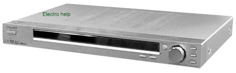
Sony STR-KSL50 HOME THEATER SYSTEM test modes and schematic


AEP Model, UK Model, E Model.  STR-KSL50 is the receiver section in HT-SL50.

TEST MODE.

FACTORY PRESET MODE
* All preset contents are reset to the default setting.
* Procedure:
While depressing the PLII and the PRESET TUNING + buttons simultaneously, press the power  button to turn on the main power. The message “FACTORY” appears and the present contents are reset to the default values.

RDS AUTOBETICAL MODE
* This mode is installed in the Europe models only. When this mode is used, the receiver scans the broadcasts that can be received by the tuner, and sets up the broadcasts. Be sure to start scanning after connecting the antenna.
* Procedure :
1. Check that the antenna is connected.
2. While depressing the INPUT SELECTOR button, press the Power button to turn on the main power.
3. The message “AUTO-BETICAL SELECT” appears and the receiver starts scanning.
MICRO/NORMAL SPEAKER SELECTION MODE
* Either the micro speaker mode or normal speaker mode can be selected.
* Procedure
While depressing the MUTING button, press the power button to turn on the main power. Either the message “MICRO SP.” or “NORM. SP.” appears. Select the desired mode.

SOUND FIELD CLEAR MODE
* The preset sound field is cleared when this mode is activated.
Use this mode before returning the product to clients upon completion of repair.
* Procedure:
While depressing the SOUND FIELD button, press the power  button to turn on the main power. The message “SF. CLR” appears and initialization is performed.
ALL CLEAR MODE
* The all preset value is cleared when this mode is activated.
* Procedure :
While depressing the PLII and the PRESET TUNING – buttons simultaneously, press the power  button to turn on the main power. The message “CLEARED” appears and clear all preset value.

SOFTWARE VERSION DISPLAY MODE
* The software version is displayed.
* Procedure:
While depressing the SOUND FIELD and the PRESET TUNING - buttons simultaneously, press the power  button to turn on the main power. The model name, destination and the software version are displayed.
KEY CHECK MODE
* Button check
* Procedure:
While depressing the MUTING and the INPUT SELECTOR buttons simultaneously, press the power  button to turn on the main power.  “REST 06” appears.
Every pressing of any button other than Power counts down the buttons. The buttons which are already counted once are not counted again. When all buttons are pressed “REST 00” appears.

FLUORESCENT INDICATOR TUBE TEST MODE
* All fluorescent segments are tested. When this test is activated, all segments turn on at the same time, then each segment turns on one after another.
* Procedure:
While depressing the MUTING and the PRESET TUNING - buttons simultaneously, press the power  button to turn on the main power.
1. All segments turn on.


4. Press the INPUT SELECTOR button, all segments and LEDs turn off.
5. Every pressing of the INPUT SELECTOR button turns on each segment and LED one after another in the same order.

TUNER CHECK MODE
* Tuner check
* Procedure :
While depressing the SOUND FIELD and the INPUT SELECTOR buttons simultaneously, press the power button to turn on the main power. “TUN CHK” appears and the tuner checking is performed.
DSP TEST MODE
* DSP tests are performed.
* Procedure :
There are two different methods to enter the test mode.
(1) While depressing the INPUT SELECTOR and PRESET TUNING - buttons simultaneously, press the power  button to turn on the main power.
(2) When the set is turned on, by using the remote controller, press the ENTER button three times, then press the MAIN MENU
button one time and then press the MUTING button one time.
• Select the item by pressing Cursor button ( UP OR DN ).
• Select the function by pressing Cursor button ( R OR L )

DSP test mode items


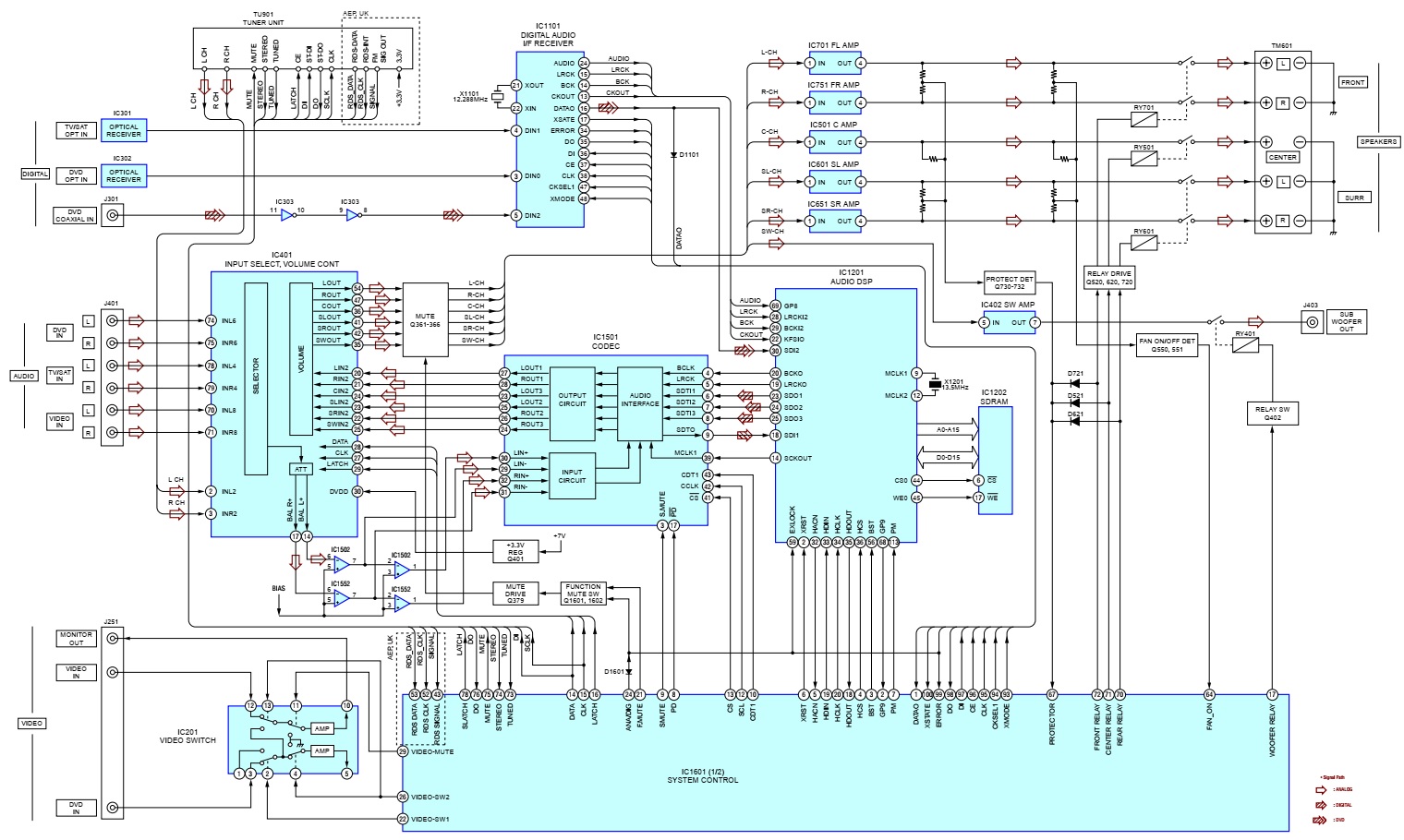
Sony STR-KSL50 block diagram


Main board PWB


Digital board PWB


Schematic Diagram – Digital (1/2) Section


Schematic Diagram – Digital (2/2) Section


Schematic Diagram – Main (1/2) Section


Schematic Diagram – Main (2/2)/Standby Section


Schematic Diagram – Display Section