Monday, September 02, 2013

PANASONIC AK 630EE - HOW TO Disassemble CD mechanism – Main PCB – Sub-Power PCB and Power Amplifier IC

CD MECHANISM UNIT
  • Remove one screw at rear panel.
  • Detach the FFC wires (CN2801 & CN2805).
  • Release the claws of both ends, and then lift up the CD Mechanism Unit.
  • Remove 4 screws.
  • Remove the CD chassis.
  • Lay the CD mechanism unit as shown.
LASER ASS'Y
MAIN PCB
  • Disconnect FFC wires CN2803 & CN2806from Main P.C.B.
  • Lift up Main P.C.B. by disconnecting connectors CN5800 & CN5801 as arrow shown.
  • Remove the 2 screws fixed at Sub Power P.C.B.
  • Remove 2 screws at Power Amplifier IC.
  • Disconnect connector CN5803
  • Lift up the Sub Power P.C.B. to remove it.
POWER AMPLIFIER IC REPLACEMENT
  • Desolder the terminals of Power Amplifier IC and replace the component.
  • Remove the 2 screws fixed at heat sink.
  • Remove 1 screw fixed at Power P.C.B.
Insulate the Power P.C.B. with insulation material to avoid short circuit.


ERROR CODES - PANASONIC SA AK630 - SELF DIAGNOSIS - CD TEST MODE

CR-20 MECHANISM ERROR CODES
If mechanism problem occurs during normal or aging mode, the error code is “remembered” and shown on the FL display.
Reset Condition of Error Code
a. During cold start of micro-processor IC.
b. Restart of ageing mode for the mechanism unit.
 Mechanism Error Code.
CLICK ON PICTURES TO ZOOM.  Click ß at the top left of the browser to come back.

When the mechanism unit stops due to error during aging model, error code misremembered and counts of the errors are displayed on the FL display.
SELF DIAGNOSIS FUNCTION
To enter self diagnosis mode
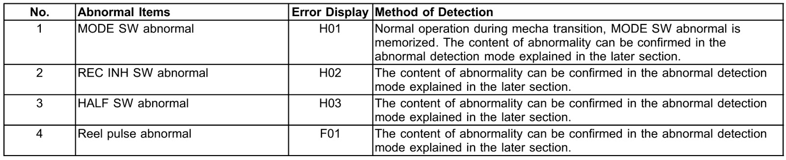
Cassette Mechanism Test (For error code H01, H02, H03, F01)
  1. Press “TAPE, DECK 1/2” to select Deck 2.
  2. Load a cassette tape with the erasure prevention tab, remove from left side only and close the cassette holder.
  3. Press “FASTFORWARDMEMORY” (Tape will be stop after 2 seconds)
  4. Load a cassette tape with the erasure prevention tab, remove from right sideonly and close the cassette holder.
  5. Press “REVERSE FM MODE/BP” (Tape will be stop after 2 seconds)
  6. Load a pre-recorded tape with both side record tabs intact and close the cassette holder.
  7. Press “PLAY/TUNE/TIME ADJ UP” (After TPS function, tape will stop automatically)
  8. Press “REC/STOP” (Tape will not move)
  9. Press “STOP/TUNE MODE” to indicate Error code.  If several problem exist, error code will change each time when “n/STOP” is pressed. (e.g. H01 -->H03 -->F01 .....etc.)
  10. Press “TAPE, DECK 1/2” to select Deck 1.
  11. Repeat step 2 to 9 to test Deck 1. (Tape Deck 1 will not check H02 because of no recording function).
CD Mechanism Test (F15, F26, F16, F17, F27, F28, F29, F30, H15 & H16)
  • Press [►/pause, CD]  (set to CD Mode) on main unit.
  • Press “CD DIRECT PLAY (1)” and [Eject, open/close] button on main unit.
  • Press [eject, open/close] to close the tray.
  • Press “CD DIRECT PLAY (5)” and [eject, open/close] wait until the tray is open.
  • Press [eject, open/close] and remove the CD.
  • Press [eject, open/close] to close the tray.
  • Press “n/STOP” to indicate Error Code.   If several problem exist, error code will change each time when “n/STOP” is pressed. (e.g. F15 --> F26 --> F16 ....etc).
TO CLEAR ALL ERROR CODES
  • Press and hold [stop] button for 5 seconds.
  • FL indicator shows “CLEAR” for 1 second and change to “T”
To exit from Self-Diagnostic function
Press [Power] button on main unit or remote control.
Power Amplifier Failure (F61)
When power amplifier fail, F61 will indicate automatically.
Abnormality detection for Deck Mechanism
Abnormality detection for CD/Changer
Power supply related error
Error Display: F61
  • During normal operation, if DCDET becomes ‘L’, normal POWER OFF process shall not be executed, PCNT shall be switched to ‘L’ immediately. GOODBYE shall not be displayed and the error display F61 will be displayed instead.  2 seconds after the F61 display, ECONO shall be set to ‘L’ and FL display shall be turned off.
  • The error content shall be memorized when the abnormality occurs and can be displayed in the C-mecha self-diagnostic mode described later.
CD TEST MODE
CD test mode is provided to check CD unit without connecting to changer loading mechanism. This mode shall operate CD PLAY with CD unit being connected only and CD Automatic Alignment result is shown on FL display.
Under CD test mode, pressing the numeric key ‘0’ on the remote controller will display the auto adjustment result. FLOCK, TLOCK and CLVS status shall be shown as below:
During the above display, executing CD PLAY will display auto adjustment result for CD PLAY mode.
CD MECHA AGING TEST MODE
Functional summary of CD aging test mode.  It is for the purpose to determine the reliability of the CD changer.
First, enter into self-diagnostic mode.
In the self-diagnostic mode, switch the SELECTOR to [►/PAUSE, CD] and press [|<</REW/v]. It will enter into CD aging test mode.
When in CD aging test mode, the following operation will begin and repeated:
  1. [DISC STOCKER] àDISC LOAD àTRAY OPEN (2 secs) àTRAY CLOSE] as one count.
  2. DISC 1 àDISC 2 àDISC 3 àDISC 4 àDISC 5 àDISC 1........repeating this endlessly.   While performing the above operation, the FLdisplay will show the number of its operations starting from 00001.
It shall move up one counter when the above operations end. The counter will reset to 00000 when 99999 is reached.  
To exit CD aging test mode, press [POWER] button, the tray will return to its PLAY position and power will be off.
MICON ROM CHECKSUM AND VERSION DISPLAY MODE
To enter into Micon ROM checksum and Version Display Mode.
  • Enter into Self-Diagnostic Mode.
  • In the Self-Diagnostic Mode, Press [►/PAUSE, CD] twice.
The version number and the calculated ROM Checksum of the current software will be displayed on the FL as shown in this example:
The Software Version No. & Micon Software Checksum differs from set to set.
The ROM Checksum is calculated on demand, not hard coded.
The ROM Checksum is calculated by talking the arithmetic SUM of the ROM contents from the program’s START address until the END address.
START address = [1080]H
END address = [FFFD]H

Sunday, September 01, 2013

PANASONIC SA AK630 - HOW TO REPLACE BELTS - CAPSTAN BELT - WINDING BELT


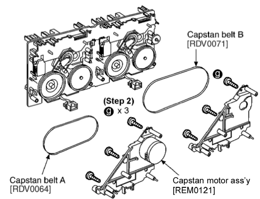
MOTOR ASS'Y, CAPSTAN BELT & WINDING BELT REPLACEMENT
  • Release the 2 claws, and then remove the head connector.
  • De-solder plunger point.
  • Remove the Deck Mechanism P.C.B.
CLICK ON PICTURES TO ZOOMClick ß at the top of the browser to return.
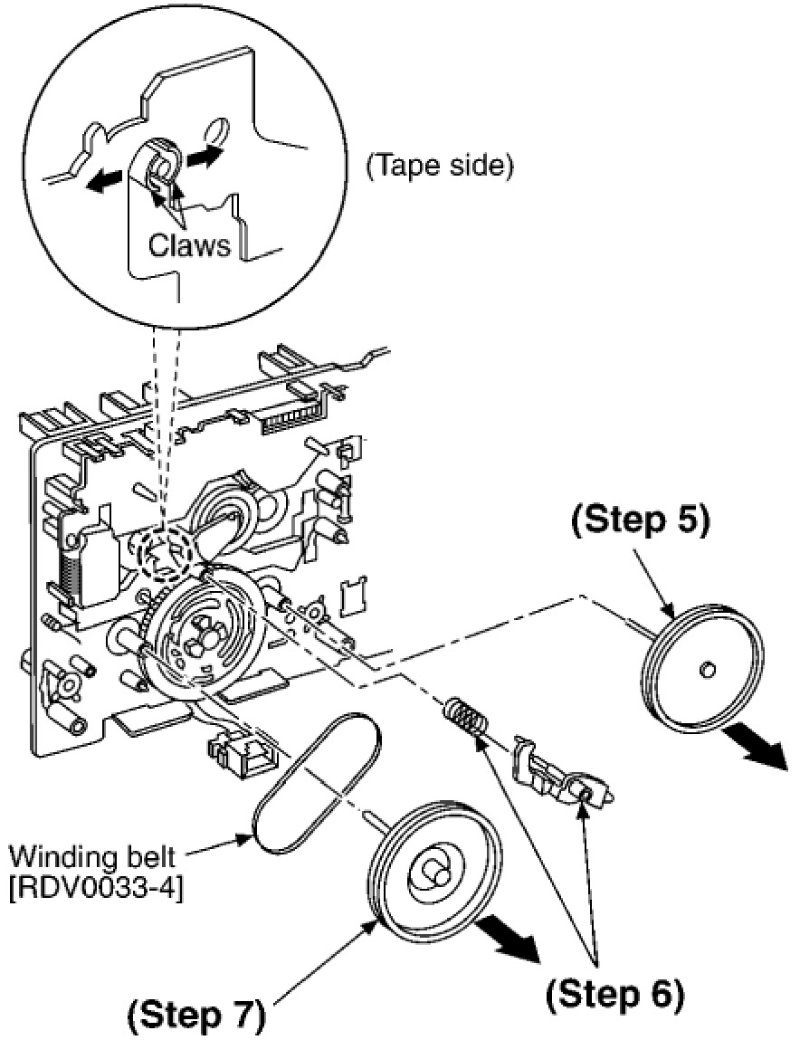
  • Remove 3 screws.
  • Remove the flywheel R.
  • Release the claw of tape side, and then remove the winding lever and spring.
  • Remove the flywheel F
INSTALLATION OF BELT
  • The boss and marking should be positioned horizontally.
  • Put the winding belt on the pulley temporarily.
  • Install the flywheel F.
  • Put the winding belt on the flywheel F.
  • Install the winding lever and spring while pressing the winding arm in the direction of arrow.
  • Install the flywheel R.
  • Put the capstan belt A temporarily as shown below.
  • Put the capstan belt B on the motor assy’s pulley.
  • Install the sub chassis to the mechanism, and then tighten screws.
  • Remove 3 screws.
  • Put the capstan belt B as shown below.
  • Put the capstan belt A on the motor ass’y pulley.

HOW TO DISASSEMBLE TOP CABINET – CD LID & REAR PANEL- PANASONIC SA-AK630


TOP CABINET REMOVAL
  • Remove 2 screws at each side and 5 screws at rear panel.
  • Lift up both sides of the top cabinet, push the top cabinet towards the rear and remove the top cabinet.
CD LID DISASSEMBLY
Opening the disc tray automatically (Using Power Supply)
  • Connect the AC power cord.
  • Press the POWER button to power up the main unit.
  • Press the OPEN/CLOSE button, the disc tray will open automatically.
  • Release the 2 claws, and then remove the CD Lid.
  • Press the OPEN/CLOSE button, the disc tray will close.
  • Press the POWER button to turn the power off.
[Opening the disc tray manually (Using service tools)]
  • Insert the gear tool into the hole on the underside of CD chassis and then rotate in the direction of arrow. The disc tray will be opened.
  • Release the 2 claws, and then remove the CD lid cover.
  • Repeat Step 2 but rotate the gear tools in anti-clockwise direction.
  • The disc tray will be closed.

SHARP MX FN12 - HOW TO DISASSEMBLE PAPER PASS UNIT - - DIGITAL FULL COLOR MULTIFUNCTIONAL SYSTEM OPTION FINISHER


FINISHER
  • Remove the hand screw from the finisher connection connector on the rear side of the machine, and remove the machine connection harness from the finisher.
  • Open the front cover of the finisher.
  • Turn the separation lever to the left to separate the finisher from the machine. Slide the finisher to the left until it stops.

  • While pushing the lock lever to the bottom, slide the finisher a little to release the lock.
NOTE: To prevent against falling, do not slide the finisher excessively with the lock released.
  • Remove the finisher from the machine connection unit.
NOTE: When holding the finisher, hold the front frame side and the rear frame side together.
PAPER PASS UNIT
Remove the screw, and remove the paper pass unit.
UPPER PAPER GUIDE
Remove the screw, and slide the finisher upper paper guide to the front side to remove.
FRONT CABINET - RIGHT
Remove the screw, and remove the separation lever.
Remove the screw, and remove the front cabinet right.
REAR CABINET & IF MAIN PWB COVER
Remove the screw, and disengage the pawl and remove the rear cabinet.
Remove the screw, and slide the IF main PWB cover to the front side to remove.

SHARP ER A410 - ER A420 - HOW TO UPGRADE READ ONLY MEMORY [ROM]

ROM A410A 420U
MODEL NAME  :  ER-A410, ER-A420
ROM SIZE    :  512KBytes(4Mbits)
FILE NAME   :  A420U_2B.ROM
ROM VERSION :  28F40RCC2B
CHECK SUM   :  A610
ERA 420 ROM LOADING
Sharp has released a new POSUTILITYTOOLS.exe program.
POSUTILITYTOOLS3.exe is to be used to download the ROM image to the ERA410/20 machine follow the procedure below.
The exe file as well as ROM images can be found on the Sharp Technical Web Site.
Procedure to load image via POSutilitytool3 program:
Put ER-A410/20 into IPL Mode, using the following procedure:
  • Turn off the power switch of ER-A420 and turn modeswitch to SRV position.
  • Holding down Receipt paper feed key, Journal paper feed key and Void key, turn on power switch of ER-420.  "IPL" is shown on operator display.  Then you can load the ROM object to ER-A420 by POS utility tool3 via RS232.
TO UPGRADE THE ERA420 ROM IMAGE
Before working on the installation, unplug the AC code from the AC outlet.
  • Open the top cabinet.
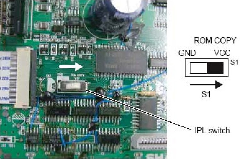
  • Set the IPL switch (S1) to ROM COPY position.
  • Install the IPL ROM to the IC socket of the MAIN PWB.
  • Turn the mode key switch to SRV’ position, and insert AC plug in AC outlet.
  • Turn the mode key switch to SRV position. The IPL procedure is started.
When the procedure is completed, the message of “Completed.” Is shown.
CLICK ON PICTURES TO ZOOM. {Click ß at the top left of the browser to come back.}
  • Unplug the AC code from the AC outlet.
  • Remove the IPL ROM to the IC socket of the MAIN PWB.
  • Set the IPL switch (S1) to GND position.
  • Replace the top cabinet.
  • Perform the master reset.
Turn the mode key switch to the SRV’ position, insert AC plug in AC outlet.  While holding down Journal feed key, turn to SRV position from SRV’ position.