Saturday, August 15, 2015

TOYOTA Corolla CQ-ES7880AZ – CIRCUIT DIAGRAM and CONNECTION DETAILS – EXPLODED VIEW

CQ-ES7880AZ AM/FM/MPX ELECTRONIC TUNING RADIO with 6-Disc CD Changer - TOYOTA Corolla
Power Supply DC 12V (10.5V - 16V),
Test Voltage 13.2V
Negative Ground
Current Consumption 3A or less (at illumi on)
Dark Current 0.3mA or less.
CD Changer (YGFD53316)
Destination: Brazil
EXPLODED VIEW & REAR SOCKET CONNECTION DETAILS
CIRCUIT DIAGRAMS - MAIN BLOCK & DISPLAY BLOCK
CLICK ON THE SCHEMATICS TO ZOOM IN

SAMSUNG 713N TFT LCD - MONITOR – HOW TO ENTER SERVICE MODE – ADJUSTMENTS

TFT-LCD MONITOR SAMSUNG 713N 711N 721N _Service Mode and Adjustment procedure
How to Display Service Function OSD
1. The value for brightness and contrast should be changed to zero.
2. Within 5 seconds, press the (Enter/Source) key.
3. Service function OSD will be displayed.
To disable [Exit] the service function OSD;  power off the unit.
The service function OSD is based on a grid of 29 columns x 12 rows.
The service function OSD consists of panel information, software version and MICOM checksum.
To Control Service Function OSD With the panel selected on OSD, whenever you press the right key, the base color will change to blue from “Panel” to “Upper Lamp”, “Lower Lamp”.
The case of panel change
After changing the panel,
press the menu key within 5 seconds
, then, panel Ch. No increases one step and the panel time information is reset to zero.
Simultaneously, other information is reset to zero (Upper/Lower lamp, Panel cycle).
In the case of Upper Lamp or Lower Lamp change
After changing the Upper Lamp or Lower Lamp,
1. Select the Upper Lamp or Lower Lamp
2. Press the Menu key within an 5 seconds.
Then, Ch. No and time will be reset to zero (selected item only).

Friday, August 14, 2015

How a 2-stroke Engine works – Principle - Troubleshooting

The 2-Stroke Internal Combustion Engine Troubleshooting
A two-stroke cycle or “two-cycle” engine produces one power stroke for every revolution of its crankshaft. Intake and compression occur during the piston’s “up” stroke; power and exhaust occur during the “down” stroke.  Six distinct processes occur during every revolution of the crankshaft, and a loss or weakness of even one of these processes will affect the other five.
Piston Ported Induction
1. Intake
As the piston moves up toward the cylinder head, a low pressure (vacuum) is created in the crankcase. As the moving piston uncovers the intake port, atmospheric pressure pushes a fresh charge of fuel-air mixture into the crankcase.  The mixture accomplishes two functions before it is moved to the combustion chamber:
■ Oil suspended in the mixture coats all internal engine parts including cylinder walls, crankshaft, and bearings.
■ The atomized fuel mixture absorbs heat as it enters the crankcase, lowering the engine’s operating temperature.
2. Compression
As the piston continues to move upward and cover the cylinder ports, the combustion chamber is sealed and compression begins.  The air-fuel mixture introduced during the previous revolution’s transfer cycle is now trapped and becomes compressed between the piston and cylinder head.
3. Ignition
As the piston approaches the top of the cylinder, the spark plug fires and ignites the fuel-air mixture. To compensate for increases in engine rpm, spark timing is advanced electronically.

4. Power (combustion)
The fuel-air mixture expands rapidly as it burns, forcing the piston down the cylinder.  Piston movement is transferred to the crankshaft through the connecting rod, rotating the crankshaft.
5. Exhaust
Expanding gasses continue to force the piston downward, exposing the exhaust port. Most of the spent combustion gasses are expelled through the exhaust port.
6. Transfer
The piston’s downward movement covers the intake port and uncovers the transfer port, while simultaneously compressing the fresh fuel-air mixture drawn into the crankcase during Step 1. As the transfer port is uncovered, the fresh mixture swirls rapidly into the cylinder.
As the fresh fuel-air mixture enters the cylinder, it also helps to push or scavenge any remaining exhaust gasses out through the exhaust port.
The burning mixture expands, forcing the piston down and compressing the fresh mixture in the crankcase. As the piston exposes the transfer port, crankcase pressure forces fresh mixture into the combustion chamber and helps push the remaining exhaust gasses through the exhaust port.
1.Intake
As the piston moves up toward the cylinder head, low pressure (vacuum) created in the crankcase allows atmospheric pressure to open the reed valve and push a fresh charge of fuel-air mixture into the crankcase.  The fuel-air mixture accomplishes two functions before it is moved to the combustion chamber:
■ Oil suspended in the mixture coats all internal engine parts including cylinder walls, crankshaft, and bearings.
■ The atomized fuel mixture absorbs heat from the crankcase, lowering the engine’s operating temperature.
2.Compression
As the piston continues to move upward and cover the cylinder ports, the combustion chamber is sealed and compression begins.  The air-fuel mixture introduced during the previous revolution’s transfer cycle is now trapped and becomes compressed between the piston and cylinder head.
3. Ignition
As the piston approaches the cylinder head, the spark plug fires and ignites the fuel-air mixture. To compensate for increases in engine rpm, spark timing is advanced electronically.
Reed Valve Induction System (reed valve open)
4. Power (combustion)
The fuel-air mixture expands rapidly as it burns, forcing the piston down the cylinder.  Piston movement is transferred to the crankshaft through the connecting rod, rotating the crankshaft.
5. Exhaust
Expanding gasses continue to force the piston downward, exposing the exhaust port. Most of the spent combustion gasses are expelled through the exhaust port.
6. Transfer
The piston’s downward movement compresses the fuel-air mixture drawn into the crankcase during Step 1, causing the reed valve to close. As the moving piston uncovers the transfer port, the fresh mixture swirls rapidly into the cylinder.  As the fresh fuel-air mixture enters the cylinder, it also helps to push or scavenge any remaining exhaust gasses out through the exhaust port.
Troubleshooting
Mechanical failure of any carburetor is far less common than problems arising from contaminated fuel, improper adjustment, or operator abuse.  Carburetor operation is directly affected by the quality of air and fuel entering the carburetor! Before troubleshooting or adjusting any carburetor, inspect fuel and air filters for cleanliness, operation, and proper installation.
1.Is the fuel tank filled with clean, fresh fuel of the proper grade and mixture?
2. Check for spark.
3. Compression at least 100 psi or above?
4. Is the air filter clean and properly installed?
5. Are the spark arrestor and muffler clean and properly installed?
6. Inspect fuel filter, and check fuel lines for leaks/deterioration. Pressure-test fuel system for leaks.
7. Inspect the impulse tube or passage for condition and operation. Pressure-test crankcase as required.
8. Inspect the tank vent. Clean or replace as required
9. Reset carburetor mixture adjustments.
10. Pressure test the carburetor for pop-off and reseat values.

Thursday, August 13, 2015

HOW TO ENTER SERVICE MODE - ERAE EPT-4200AP 42 inch Plasma TV Troubleshooting

All plasma TVs have similar structure both in circuit and function; except its screen size.  So this troubleshooting procedure can be taken as a guide to troubleshoot Plasma TVs
VOLTAGE & W/B ADJUSTMENT
Power PCB Assy Voltage Adjustment
Va Adjustment (Address Voltage Adjustment)
Connect pin 9,10 of CN806 to(+) jack of D.M.M
After turning the VR2 (Va Adj),Voltage of D.M.M adjustment as same as Va voltage which on
Label of panel right/bottom.(Deviation : ± 0.5V)
Vs Adjustment
Connect pin 1~3 of CN806 to (+) jack of D.M.M
After turning the VR3 (Vs Adj),voltage of D.M.M adjustment as same as Vs voltage which
indicated on Label of panel right/bottom.(Deviation : ± 0.5V)
Va : 65V
Vs : 190V
(These two voltages will differ from panel to panel, and can be noted at the silk screen on the back of the panel. It is important to adjust these two voltages as specified; and is a must; especially when you replace or repair the SMPS board, or replace the display panel. There will be presets in the power supply section (SMPS) of every plasma TVs to adjust these voltages, and will be marked as Vs & Va adjust.)
POWER SEQUENCE
1.After Relay On
• 2. Continue 5Volt Monitoring – If there is no 5Volt more than 10 minutes, then
• power “Off”
• 3. Check if it is OK the 5Volt Mnt first. And then VaVs “On” after 3 seconds.
• 4. VaVs “On” --> waiting 3 seconds --> Display Enable “On”. 5. If 5Volt Mnt “Low” or AC-Det “Low”, immediately Display Enable “Off” and then VaVs “Off”, Relay “Off”.
2. W/B adjustment
 Color temperature (White Balance) adjustment
How to enter Factory mode for adjustment of White Balance
(1) PDP TV Power “On” --> Input select key on Remote control.
(2) Choose composite first and then PDP TV Power “Off”.
(3) PDP TV Power “Off” and INFO on the R/C => ERASE => ENTER Key
For COMPOSITE adjustment (manual adjustment)
(1) Signal Generator supply the pattern of above picture. (Timing ⇒ 386, Pattem ⇒ 10)
(2) After movement to 2.color control on Factory Mode2, move to sub menu as choice of volume button.
(3) After check the Brightness ⇒ 50, Contrast ⇒ 90, choose the Sub-Brightness.
(4) Zero calibration’s execution of CA-100 and the sensor should be closed to surface of PDP module.
(5) Adjustment as choice of volume button in order that it becomes Y= 6.0 ±0.5 cd/m² on the sub brightness.
(6) Color coordinates’ adjustment of Red Offset, Green Offset, Blue Offset using this kind of method.
Color coordination ⇒ x= 0.281 ±0.007, y=0.295 ±0.007, Y= 6.0 ±0.5 cd/m² (Color temperature : 9500° K ± 500°K)
(7) The Sub-Brightness’ readjustment when it is not satisfied with brightness after adjustment.
Checking for no Picture
A screen doesn’t display at all and condition of black pattern or power off.
(1) Check whether the CTRL B/D LED(D1~D4) is turned on or not.
(2) Check the power and signal cable of CTRL B/D.
(3) X B/D, Y B/D, Z B/D is well plugged in.
(4) Check the connection of X B/D, Y B/D and Z B/D to CTRL B/D.
(5) Measure the output wave of X, Y, Z B/D with oscilloscope(more than 200MHz)
and find the trouble of B/D by comparing the output wave with below figure.
> Measure Point fo Y B/D : TP (Connector P4 80 pin)
> Measure Point fo Z B/D : Connection part of panel (SUS_OUT)
> Measure Point fo X B/D : L1(RIGHT), L2(LEFT BOTTOM)
(6) Check the SCAN(Y side) IC
(7) Check the DATA(X side) COF IC
(8) Replace the CTRL B/D.
Hitch Diagnosis Following Display Condition
4/7 or 3/7 of the screen doesn’t be shown
(1) Confirm the power connector of X B/D is well plugged in which is correspond to not showing screen.
(2) Confirm the connector that is connected between CTRL B/D and X B/D correspond to not showing part.
(3) Replace relevant X B/D.
The screen doesn’t be shown as Data COF
(1) The problem between Data COF and X B/D is more possible that the screen is not be shown as data COF.
(2) Confirm the connector of Data COF is well connected to X B/D. Correspond to the part that screen is not showing
(3) Confirm whether the Data COF is failed and replace X B/D
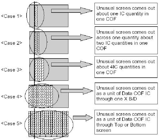
How to examine Data COF IC
Generates Unusual Pattern of Data COF IC unit
(1) In case of generating unusual pattern of Data COF IC unit as below picture, there is problem in the check that is input into Data COF IC
(2) In case of <case 1, 2, 3>
> confirm the connection of Data COF connector
> replace the relevant X B/D
(3) In case of <case 4, 5>
> confirm the connector that is connected from CTRL to X B/D
> Replace relevant XB/D or CTRL B/D
Screen Display Form
Regular Stripe is Generated about the Quantity of one Data COF IC or more
(1) In case of generating regular stripe about the quantity of one Data COF IC, there is problem at the output of output flatworm of X B/D  In case of generating regular stripe about the quantity of two Data COF IC, that means the data which is conveyed from CTRL B/D doesn’t conveyed well.
(2) Confirm the XB/D connection connector plugged in well.
Correspond to unusual screen.
(3) Replace relevant XB/D or CTRL B/D.
The screen display has a problem for Scan FFC.
(1) It’s may be a problem between Scan FFC and Y B/D.
(2) Check the connection of Y B/D and Scan COF.
(3) If the Scan IC is failed, replace the Y DRV B/D.
Check a method of SCAN IC
The screen has a vertical line with regular gap. (A vertical stripe flash at especial color)
(1) This is a problem about control B/D.
(2) Replace Control B/D.
A data copy is happened into vertical direction
(1) In this case, it’s due to incorrect marking of scan wave.
(2) Replace a Y DRV B/D or Y SUS B/D.
The screen has one or several vertical line
(1) In this case, It isn’t a problem about controller B/D or X B/D.
(2) It may cause followings.
> It’s out of order a panel
> Open or short of DATA COF FPC attached panel
> It’s out of order a DATA COF attached panel
(3) Replace Module.
The screen has one or several horizontal line
(1) In this case, it isn’t a problem about controller B/D or X B/D.
(2) It may cause followings.
> It’s out of order a panel
> Open or short of SCAN FPC attached panel
> It’s out of order a SCAN IC attached panel
(3) Replace Y DRV B/D
The screen displays input signal pattern but the brightness is dark
(1) In this case, Z B/D operation isn’t complete.
(2) Check the power cord of Z B/D.
(3) Check the connector of Z B/D and Controller B/D.
(4) Replace the Controller B/D or Z B/D.
The screen displays other color partially on full white screen or happens discharge partially on full black screen.
(1) Check the declination of Y B/D set up set down wave.
(2) Check the declination of Z B/D ¢«ramp wave.
(3) Measure each output wave with oscilloscope (more than 200MHz) Adjust the Y B/D set up(Test-up:B/C[¥s/¥s])/setdown(Testdown: D[¥s]) and Z B/D ramp(Tramp:F/G[¥s/¥s]) declination by changing VR1/VR2/VR3.
> Measuring Point of Y B/D : P4 (Connector P4 36 pin)
> Measuring Point of Z B/D : B37 (SUS_OUT)
A center of screen is darker than  edge of screen at full white pattern.
(1) In this case, it’s a problem about Z B/D ramp wave.
(2) Check the connection cable of Z B/D and CTRL B/D.
(3) Replace the Z B/D.
It doesn’t display a specified brightness at specified color
(1) Check the connector of CTRL B/D input signal.
(2) Replace the CTRL B/D.

Wednesday, August 12, 2015

HOW TO Remove HDD Password and BIOS Password – ACER ASPIRE 5737Z Series Laptop Computers

Acer Aspire-5737Z Series Laptops_BIOS password cleaning_HDD password removal _ BIOS recovery
TO REMOVE THE HDD PASSWORD
If you key in the wrong HDD password three time, HDD password error code displays on the screen.
To reset the HDD password, perform the following steps
1. From a DOS prompt, key in Unlock6.exe 05149 and press <Enter>.
The Unlock 6 program runs.
2. Select option 2, Upper case ASCII Code, and press <Enter>.
3. Make a note of one of the displayed passwords, for example B99TPK0, as shown.
4. Power off the system by holding down the power button for >4 seconds.
5. Reboot the system and key in the chosen password to unlock the HDD.
BIOS PASSWORD REMOVAL
If you key in the wrong Supervisor Password three times, System Disabled displays on the screen. See the image below.
To reset the BIOS password, run BIOS_PW.EXE as follows:
1. Key in bios_pw 14452 0
2. Select one string from the list.
Reboot the system and key in the selected string (qjjg9vy, 07yqmjd etc.) for the BIOS user password.
CLEANING BIOS PASSWORD
To clear the password, perform the following steps:
1. From a DOS prompt, Execute clnpwd.exe
Press 1, 2, or 3 to clean the desired password shown on the screen.
The on screen message determines whether the function is successful or not.
Steps for Clearing BIOS Password Check
If users set BIOS Password (Supervisor Password and/or User Password) for a security reason, BIOS will ask the password during systems POST or when systems enter to BIOS Setup menu. However, once it is necessary to bypass the password check, users need to short the HW Gap to clear the password by the following steps:
• Power Off a system, and remove HDD, AC and Battery from the machine.
• Open the back cover of the machine, and find out the HW Gap on M/B as picture.
• Use an electric conductivity tool to short the two points of the HW Gap.
• Plug in AC, keep the short condition on the HW Gap, and press Power Button to power on the system till BIOS POST finish. Then remove the tool from the HW Gap.
• Restart system. Press F2 key to enter BIOS Setup menu.
• If there is no Password request, BIOS Password is cleared. Otherwise, please follow the steps and try again.
NOTE: The steps are only for clearing BIOS Password (Supervisor Password and User Password).
BIOS Recovery by Crisis Disk
BIOS Recovery Boot Block
BIOS Recovery Boot Block is a special block of BIOS. It is used to boot up the system with minimum BIOS initialization. Users can enable this feature to restore the BIOS firmware to a successful one once the previous BIOS flashing process failed.
BIOS Recovery Hotkey
The system provides a function hotkey: Fn+Esc, for enable BIOS Recovery process when system is powered on during BIOS POST. To use this function, it is strongly recommended to have the AC adapter and Battery present. If this function is enabled, the system will force the BIOS to enter a special BIOS block, called Boot Block.
Steps for BIOS Recovery from USB Storage
Before doing this, prepare the Crisis USB key. The Crisis USB key could be made by executing the Crisis Disk program in another system with Windows XP OS.
Follow the steps below
1. Save ROM file (file name: JAL90x64.fd) to the root directory of USB storage.
2. Plug USB storage into USB port.
3. Press Fn + ESC button then plug in AC.
The Power button flashes once.
4. Press Power button to initiate system CRISIS mode.  When CRISIS is complete, the system auto restarts with a workable BIOS.
5. Update the latest version BIOS for this machine by regular BIOS flashing process.
Steps for BIOS Recovery by Crisis Disk
Before doing this, a Crisis Diskette should be prepared ready in hand. The Crisis Diskette could be made by executing the Crisis Disk program in another system with Windows XP OS.
Follow the steps below:
1. Power Off failed system.
2. Attach a USB floppy drive to the failed system.
3. Copy xxxxx.wph to tool's folder and rename it as BIOS.wph.
4. Execute wincris.exe to start the Crisis Disk Build.
5. Select Removable and click Start.
A confirmation screen displays.
6. Click the OK button on the left to continue.
7. Click the (N) button when prompted to complete the process.
8. Insert the Crisis Disk in to the USB floppy drive attached to the BIOS flash failed system.
9. In the power-off state, unplug the AC power and hold Fn+Esc then plug the AC power in.
10. Press the Power button.
The system powers on and the Crisis BIOS Recovery process begins.
BIOS Boot Block begins restoring the BIOS code from the Crisis floppy disk to BIOS ROM on the failed systems.
When the Crisis flash process is finished, the system restarts with a workable BIOS.
Update to the latest version BIOS for the system using the regular BIOS flashing process.

Acer Aspire 5737Z – Troubleshooting – BIOS Beep Codes

Common Problems
Use the following procedure as a guide for computer problems.
NOTE: The diagnostic tests are intended to test only Acer products. Non-Acer products, prototype cards, or modified options can give false errors and invalid system responses.
1. Obtain the failing symptoms in as much detail as possible.
2. Verify the symptoms by attempting to re-create the failure by running the diagnostic test or by repeating the same operation.
Power On Issue
If the system doesn’t power on, perform the following actions one at a time to correct the problem. Do not replace a non-defective FRUs:
Computer Shutdown Intermittently
If the system powers off at intervals, perform the following actions one at a time to correct the problem.
1. Check the power cable is properly connected to the computer and the electrical outlet.
2. Remove any extension cables between the computer and the outlet.
3. Remove any surge protectors between the computer and the electrical outlet. Plug the computer directly into a known good electrical outlet.
4. Disconnect the power and open the casing to check the Thermal Unit and fan airways are free of obstructions.
5. Remove all external and non-essential hardware connected to the computer that are not necessary to boot the computer to the failure point.
6. Remove any recently installed software.
No Display Issue
If the Display doesn’t work, perform the following actions one at a time to correct the problem. Do not replace non-defective FRUs:
No POST [Power On Self Test] or Video
If the POST or video doesn’t display, perform the following actions one at a time to correct the problem.
1. Make sure that the internal display is selected. On this notebook model, switching between the internal display and the external display is done by pressing Fn+F5. Reference Product pages for specific model
procedures.
2. Make sure the computer has power by checking at least one of the following occurs:
• Fans start up
• Status LEDs light up
3. Drain any stored power by removing the power cable and battery and holding down the power button for 10 seconds. Reconnect the power and reboot the computer.
4. Connect an external monitor to the computer and switch between the internal display and the external display is by pressing Fn+F5 (on this model).  If the POST or video appears on the external display,“LCD Failure”.
5. Disconnect power and all external devices including port replicators or docking stations. Remove any memory cards and CD/DVD discs. Restart the computer.  If the computer boots correctly, add the devices one by one until the failure point is discovered.
6. Reseat the memory modules.
Abnormal Video Display
If video displays abnormally, perform the following actions one at a time to correct the problem.
1. Reboot the computer.
2. If permanent vertical/horizontal lines or dark spots display in the same location, the LCD is faulty and should be replaced.
3. If extensive pixel damage is present (different colored spots in the same locations on the screen), the LCD is faulty and should be replaced.
4. Adjust the brightness to its highest level. See the User Manual for instructions on adjusting settings.
NOTE: Ensure that the computer is not running on battery alone as this may reduce display brightness.  If the display is too dim at the highest brightness setting, the LCD is faulty and should be replaced
5. Check the display resolution is correctly configured:
a. Minimize or close all Windows.
b. If display size is only abnormal in an application, check the view settings and control/mouse wheel zoom feature in the application.
c. If desktop display resolution is not normal, right-click on the desktop and select
Personalize´ Display Settings.
d. Click and drag the Resolution slider to the desired resolution.
e. Click Apply and check the display. Readjust if necessary.
6. Roll back the video driver to the previous version if updated.
7. Remove and reinstall the video driver.
8. Check the Device Manager to determine that:
• The device is properly installed. There are no red Xs or yellow exclamation marks.
• There are no device conflicts.
• No hardware is listed under Other Devices.
9. If the Issue is still not resolved, see “Online Support Information”
10. Run the Windows Memory Diagnostic from the operating system DVD and follow the onscreen prompts.
Random Loss of BIOS Settings
If the computer is experiencing intermittent loss of BIOS information, perform the following actions one at a time to correct the problem.
1. If the computer is more than one year old, replace the CMOS battery.
2. Run a complete virus scan using up-to-date software to ensure the computer is virus free.
3. If the computer is experiencing HDD or ODD BIOS information loss, disconnect and reconnect the power and data cables between devices.  If the BIOS settings are still lost, replace the cables.
4. If HDD information is missing from the BIOS, the drive may be defective and should be replaced.
5. Replace the Motherboard.
LCD Failure
If the LCD fails, perform the following actions one at a time to correct the problem. 
Sound Problems
If sound problems are experienced, perform the following actions one at a time to correct the problem.
1. Reboot the computer.
2. Navigate to Start´ Control Panel´ System and Maintenance´ System´ Device Manager. Check the Device Manager to determine that:
• The device is properly installed.
• There are no red Xs or yellow exclamation marks.
• There are no device conflicts.
• No hardware is listed under Other Devices.
3. Roll back the audio driver to the previous version, if updated recently.
4. Remove and reinstall the audio driver.
5. Ensure that all volume controls are set mid range:
a. Click the volume icon on the taskbar and drag the slider to 50. Ensure that the volume is not muted.
b. Click Mixer to verify that other audio applications are set to 50 and not muted.
6. Navigate to Start´ Control Panel´ Hardware and Sound´ Sound. Ensure that Speakers are selected as the default audio device (green check mark).
NOTE: If Speakers does not show, right-click on the Playback tab and select Show Disabled Devices (clear by default).
7. Select Speakers and click Configure to start Speaker Setup. Follow the onscreen prompts to configure the speakers.
8. Remove and recently installed hardware or software.
9. Restore system and file settings from a known good date using System Restore.  If the issue is not fixed, repeat the preceding steps and select an earlier time and date.
10. Reinstall the Operating System.
Microphone Problems
If internal or external Microphones do no operate correctly, perform the following actions one at a time to correct the problem.
1. Check that the microphone is enabled. Navigate to Start´ Control Panel´ Hardware and Sound´ Sound and select the Recording tab.
2. Right-click on the Recording tab and select Show Disabled Devices (clear by default).
3. The microphone appears on the Recording tab.
4. Right-click on the microphone and select Enable.
5. Select the microphone then click Properties. Select the Levels tab.
6. Increase the volume to the maximum setting and click OK.
7. Test the microphone hardware:
a. Select the microphone and click Configure.
b. Select Set up microphone.
c. Select the microphone type from the list and click Next.
d. Follow the onscreen prompts to complete the test.
HDD Not Operating Correctly
If the HDD does not operate correctly, perform the following actions one at a time to correct the problem.
1. Disconnect all external devices.
2. Run a complete virus scan using up-to-date software to ensure the computer is virus free.
3. Run the Windows Vista Startup Repair Utility:
a. insert the Windows Vista Operating System DVD in the ODD and restart the computer.
b. When prompted, press any key to start to the operating system DVD.
c. The Install Windows screen displays. Click Next.
d. Select Repair your computer.
e. The System Recovery Options screen displays. Click Next.
f. Select the appropriate operating system, and click Next.
NOTE: Click Load Drivers if controller drives are required.
g. Select Startup Repair.
h. Startup Repair attempts to locate and resolve issues with the computer.
i. When complete, click Finish.  If an issue is discovered, follow the onscreen information to resolve the problem.
4. Run the Windows Memory Diagnostic Tool. For more information see Windows Help and Support.
5. Restart the computer and press F2 to enter the BIOS Utility. Check the BIOS settings are correct and that CD/DVD drive is set as the first boot device on the Boot menu.
6. Ensure all cables and jumpers on the HDD and ODD are set correctly.
7. Remove any recently added hardware and associated software.
8. Run the Windows Disk Defragmenter. For more information see Windows Help and Support.
9. Run Windows Check Disk by entering chkdsk /r from a command prompt. For more information see Windows Help and Support.
10. Restore system and file settings from a known good date using System Restore.  If the issue is not fixed, repeat the preceding steps and select an earlier time and date.
ODD Not Operating Correctly
If the ODD exhibits any of the following symptoms it may be faulty:
• Audio CDs do not play when loaded
• DVDs do not play when loaded
• Blank discs do not burn correctly
• DVD or CD play breaks up or jumps
• Optical drive not found or not active:
• Not shown in My Computer or the BIOS setup
• LED does not flash when the computer starts up
• The tray does not eject
• Access failure screen displays
• The ODD is noisy
Perform the following general solutions one at a time to correct the problem.
1. Reboot the computer and retry the operation.
2. Try an alternate disc.
3. Navigate to Start´ Computer. Check that the ODD device is displayed in the Devices with Removable Storage panel.
4. Navigate to Start´ Control Panel´ System and Maintenance´ System´ Device Manager.
Double-click lDE ATA/ATAPI controllers. If a device displays a down arrow, right-click on the device and click Enable.
b. Double-click DVD/CD-ROM drives. If the device displays a down arrow, right-click on the device and click Enable.
c. Check that there are no yellow exclamation marks against the items in lDE ATA/ATAPI controllers. If
a device has an exclamation mark, right-click on the device and uninstall and reinstall the driver.
d. Check that there are no yellow exclamation marks against the items in DVD/CD-ROM drives. If a device has an exclamation mark, right-click on the device and uninstall and reinstall the driver.
e. If the exclamation marker is not removed from the item in the lists, try removing any recently installed software and retrying the operation.
Discs Do Not Play
If discs do not play when inserted in the drive, perform the following actions one at a time to correct the problem.
1. Check that the disc is correctly seated in the drive tray and that the label on the disc is visible.
2. Check that the media is clean and scratch free.
3. Try an alternate disc in the drive.
4. Ensure that AutoPlay is enabled:
a. Navigate to Start´ Control Panel´ Hardware and Sound´ AutoPlay.
b. Select Use AutoPlay for all media and devices.
c. In the Audio CD and DVD Movie fields, select the desired player from the drop down menu.
5. Check that the Regional Code is correct for the selected media:
IMPORTANT:Region can only be changed a limited number of times. After Changes remaining reaches zero, the region cannot be changed even Windows is reinstalled or the drive is moved to another computer.
a. Navigate to Start´ Control Panel´ System and Maintenance´ System´ Device Manager.
b. Double-click DVD/CD-ROM drives.
c. Right-click DVD drive and click Properties, then click the DVD Region tab.
d. Select the region suitable for the media inserted in the drive.
Discs Do Not Burn Properly
If discs can not be burned, perform the following actions one at a time to correct the problem.
1. Ensure that the default drive is record enabled:
a. Navigate to Start´ Computer and right-click the writable ODD icon. Click Properties.
b. Select the Recording tab. In the Desktop disc recording panel, select the writable ODD from the drop down list.
c. Click OK.
2. Ensure that the software used for burning discs is the factory default. If using different software, refer to the software's user manual
Playback is Choppy
If playback is choppy or jumps, perform the following actions one at a time to correct the problem.
1. Check that system resources are not running low:
a. Try closing some applications.
b. Reboot and try the operation again.
2. Check that the ODD controller transfer mode is set to DMA:
a. Navigate to Start´ Control Panel´ System and Maintenance´ System´ Device Manager.
b. Double-click IDE ATA/ATAPI controllers, then right-click ATA Device 0.
c. Click Properties and select the Advanced Settings tab. Ensure that the Enable DMA box is
checked and click OK.
d. Repeat for the other ATA Devices shown if applicable.
Drive Not Detected
If Windows cannot detect the drive, perform the following actions one at a time to correct the problem.
1. Restart the computer and press F2 to enter the BIOS Utility.
2. Check that the drive is detected in the ATAPI Model Name field on the Information page.
NOTE: Check that the entry is identical to one of the ODDs specified in “Hardware Specifications and Configurations”
3. Turn off the power and remove the cover to inspect the connections to the ODD.
a. Check for broken connectors on the drive, motherboard, and cables.
b. Check for bent or broken pins on the drive, motherboard, and cable connections.
c. Try an alternate cable, if available. If the drive works with the new cable, the original cable should be replaced.
4. Reseat the drive ensuring and all cables are connected correctly.
5. Replace the ODD.
Drive Read Failure
If discs cannot be read when inserted in the drive, perform the following actions one at a time to correct the problem.
1. Remove and clean the failed disc.
2. Retry reading the CD or DVD.
d. Test the drive using other discs.
e. Play a DVD movie
f. Listen to a music CD
If
the ODD works properly with alternate discs, the original disc is probably defective and should be replaced.
3. Turn off the power and remove the cover to inspect the connections to the ODD
a.Check for broken connectors on the drive, motherboard, and cables.
b. Check for bent or broken pins on the drive, motherboard, and cable connections.
c. Try an alternate cable, if available. If the drive works with the new cable, the original cable should be replaced.
4. Replace the ODD.
External Mouse Failure
If an external Mouse fails, perform the following actions one at a time to correct the problem.
1. Try an alternative mouse.
2. If the mouse uses a wireless connection, insert new batteries and confirm there is a good connection. See the mouse user manual.
3. If the mouse uses a USB connection, try an alternate USB port.
4. Try an alternative program to verify mouse operation. Reinstall the program experiencing mouse failure.
5. Restart the computer.
6. Remove any recently added hardware and associated software.
7. Remove any recently added software and reboot.
8. Restore system and file settings from a known good date using System Restore.  If the issue is not fixed, repeat the preceding steps and select an earlier time and date.
9. Run the Event Viewer to check the events log for errors. For more information see Windows Help and Support.
10. Roll back the mouse driver to the previous version if updated recently.
11. Remove and reinstall the mouse driver.
12. Check the Device Manager to determine that:
• The device is properly installed. There are no red Xs or yellow exclamation marks.
• There are no device conflicts.
Intermittent Problems
Intermittent system hang problems can be caused by a variety of reasons that have nothing to do with a hardware defect, such as: cosmic radiation, electrostatic discharge, or software errors. FRU replacement
should be considered only when a recurring problem exists.  When analyzing an intermittent problem, do the following:
1. Run the advanced diagnostic test for the system board in loop mode at least 10 times.
2. If no error is detected, do not replace any FRU.
3. If any error is detected
Undetermined Problems
The diagnostic problems does not identify which adapter or device failed, which installed devices are incorrect, whether a short circuit is suspected, or whether the system is inoperative.  Follow these procedures to isolate the failing FRU (do not isolate non-defective FRU).
NOTE: Verify that all attached devices are supported by the computer.
NOTE: Verify that the power supply being used at the time of the failure is operating correctly. 
1.Power-off the computer.
2. Visually check them for damage. If any problems are found, replace the FRU.
3. Remove or disconnect all of the following devices:
• Non-Acer devices
• Printer, mouse, and other external devices
• Battery pack
• Hard disk drive
• DIMM
• CD-ROM/Diskette drive Module
• PC Cards
4. Power-on the computer.
5. Determine if the problem has changed.
6. If the problem does not recur, reconnect the removed devices one at a time until you find the failing FRU.
7. If the problem remains, replace the following FRU one at a time. Do not replace a non-defective FRU:
• System board
• LCD assembly, replace the FRU. Rerun the test to verify that there are no more errors.
Chipset POST Codes [Bios Beep Codes]

If the BIOS detects error 2C, 2E, or 30 (base 512K RAM error), it displays an additional word-bitmap (xxxx) indicating the address line or bits that failed. For example, 2C 0002 means address line 1 (bit one set) has failed. 2E 1020 means data bits 12 and 5 (bits 12 and 5 set) have failed in the lower 16 bits. Note that error 30 cannot occur on 386SX systems because they have a 16 rather than 32-bit bus. The BIOS also sends the bitmap to the port-80 LED display. It first displays the check point code, followed by a delay, the high-order byte, another delay, and then the low-order byte of the error. It repeats this sequence continuously.
CLICK ON THE TABLES TO MAGNIFY

SANYO LCE32FX LED TV – HISENSE MSD309PX – Service Mode – Software Update – Power and Back-light Inverter Schematic

SANYO LCE32FX LED TV [PAL - NTSC]HISENSE MSD309PX [PAL - NTSC]  – Service Mode – Software Update – Power and Back-light Inverter Circuit Diagram - SMPS voltage outputs
USED ICS - NCP1271 SMPS CONTROLLER – OZ9902 BACK-LIGHT INVERTER CONTROLLER
HOW TO ENTER FACTORY (SERVICE) MODE
With factory RC (remote control)
1. Press “M” button and enter factory mode.
2. Press “Menu” button and enter factory OSD menu.
3. Press “CH+”/“CH-” button select the function menu, press “VOL+”/“VOL-” enter the selected function menu. Press “VOL+”/“VOL-” button adjust values in the menu.
4. Press “M” button to exit factory mode in the factory OSD menu. When TV outgoing factory, user cannot enter factory OSD menu with Factory Remote
Note: In the “Factory Menu”, item “Function”>”TOFAC” ,you can select “M” or “U”, default is “U”.
> M-Means you can enter factory mode with factory RC or user RC.
>> U-Means you can enter factory mode only with user’s RC. 2. Mode “M” is only used for factory production.
With user’s RC
Power on the TV.
1. Press “Menu” button and call up User OSD Menu.
2. Select“ Sound” Menu > “Balance” item.
3. Press number key 1> 9 > 6 > 9 in sequence when “Balance” item is focused.
If necessary, re-do number keys.
4. Factory OSD appears.
Press the standby button then AC turn off and restart the TV, which can exit factory OSD menu.
Software can update with USB device
1. Copy the “*.BIN” file such as “MERGE.BIN” to the root directory of a USB disk.
2. Insert the USB disk into the USB slot of the TV SET.
3. Press “Menu” button and call up User OSD Menu, choose "Channel">”Software Update(USB)” item.
4. Press “OK”, it will show a confirm message box, Press [◀] button to select “yes” in the confirm message box, to start automatic update.
5. Then it will update the software automatically, don’t power off during the updating process.
6. After the software is successfully upgraded, TV SET will restart automatically.
Note: 1. In some TV SET, ”Software Update(USB)” item maybe in “OPTION” menu. 2.After updating, you must confirm the software version in the “Factory Menu” and you'd better do " UnProtected Clear" in the “Factory Menu”.
POWER [SMPS] BOARD SCHEMATIC
The Power board have 5V&12V output. Other voltages are converted from 5V & 12V.
a Vcc-Panel is converted by N1 from 12V,5V-Tuner converted by N21 from 12V supplies to tuner.
b 3.3Vstb is converted from 5V-stb by N2, It’s standby power supply for main IC (N7), Keyboard, Remote board ,Flash( N11) and HDMI CEC.
c 12V supplies for Amplifier( N17 R2A15120FA) .
d 5VAIN supplies for main IC , Headphone and USB
e 3.3VA is converted by N4 from 5VAIN, It supplies for N39(main IC), N8(HDCP),N9(EEPROM).
f 2.5VA is converted by N5 form 5VAIN.
g 1.32V is converted by N3 from 5VAIN.
h 1.8VA is converted by N6 from 5VAIN.
i 3.3V_Demod is converted by N18 from 5VAIN, 1.2V_Demod is converted by N19 from 3.3V_Demod.
INVERTER BOARD SCHEMATIC
Board 1 (Panel has not 120HZ refurbish ratio)
Board 2 (Panel has 120HZ refurbish ratio)
[Image is reference only. Different models refer to the actual units to determine the boards.]
Click on the Pictures to Zoom In

Monday, August 10, 2015

SAMSUNG LCD TV Power Supply BN44 00438A HV332HD Power and Back light Inverter Schematic

ICs Used: ICE3BR1065JF (SMPS Control) _ OZ9938GN (Back-light Inverter Control) _ FAN7530 (PFC)
BACK LIGHT INVERTER CIRCUIT DIAGRAM
SMPS CIRCUIT DIAGRAM
CLICK ON THE SCHEMATICS TO ZOOM IN