All plasma TVs have similar structure both in circuit and function; except its screen size. So this troubleshooting procedure can be taken as a guide to troubleshoot Plasma TVs
 VOLTAGE & W/B ADJUSTMENT
Power PCB Assy Voltage Adjustment
Va Adjustment
(Address Voltage Adjustment)
Connect pin 9,10 of CN806 to(+) jack of D.M.M
After turning the VR2 (Va Adj),Voltage of D.M.M adjustment as same as Va voltage which on
Label of panel right/bottom.(Deviation : ± 0.5V)
Connect pin 9,10 of CN806 to(+) jack of D.M.M
After turning the VR2 (Va Adj),Voltage of D.M.M adjustment as same as Va voltage which on
Label of panel right/bottom.(Deviation : ± 0.5V)
Vs Adjustment
Connect pin 1~3 of CN806 to (+) jack of D.M.M
After turning the VR3 (Vs Adj),voltage of D.M.M adjustment as same as Vs voltage which
indicated on Label of panel right/bottom.(Deviation : ± 0.5V)
Connect pin 1~3 of CN806 to (+) jack of D.M.M
After turning the VR3 (Vs Adj),voltage of D.M.M adjustment as same as Vs voltage which
indicated on Label of panel right/bottom.(Deviation : ± 0.5V)
Va : 65V
Vs : 190V
Vs : 190V
(These two voltages will differ from panel to panel, and can be noted at the silk screen on the back of the panel. It is important to adjust these two voltages as specified; and is a must; especially when you replace or repair the SMPS board, or replace the display panel. There will be presets in the power supply section (SMPS) of every plasma TVs to adjust these voltages, and will be marked as Vs & Va adjust.)
POWER SEQUENCE
1.After Relay On
• 2. Continue 5Volt Monitoring – If there is no 5Volt more than 10 minutes, then
• power “Off”
• 3. Check if it is OK the 5Volt Mnt first. And then VaVs “On” after 3 seconds.
• 4. VaVs “On” --> waiting 3 seconds --> Display Enable “On”. 5. If 5Volt Mnt “Low” or AC-Det “Low”, immediately Display Enable “Off” and then VaVs “Off”, Relay “Off”.
2. W/B adjustment
Color temperature (White Balance) adjustment
How to enter Factory mode for adjustment of White Balance
(1) PDP TV Power “On” --> Input select key on Remote control.
(2) Choose composite first and then PDP TV Power “Off”.
(3) PDP TV Power “Off” and INFO on the R/C => ERASE => ENTER Key
For COMPOSITE adjustment (manual adjustment)
(1) Signal Generator supply the
pattern of above picture. (Timing ⇒ 386, Pattem ⇒ 10)
(2) After movement to 2.color control on Factory Mode2, move to sub menu as choice of volume button.
(3) After check the Brightness ⇒ 50, Contrast ⇒ 90, choose the Sub-Brightness.
(4) Zero calibration’s execution of CA-100 and the sensor should be closed to surface of PDP module.
(5) Adjustment as choice of volume button in order that it becomes Y= 6.0 ±0.5 cd/m² on the sub brightness.
(6) Color coordinates’ adjustment of Red Offset, Green Offset, Blue Offset using this kind of method.
Color coordination ⇒ x= 0.281 ±0.007, y=0.295 ±0.007, Y= 6.0 ±0.5 cd/m² (Color temperature : 9500° K ± 500°K)
(7) The Sub-Brightness’ readjustment when it is not satisfied with brightness after adjustment.
Checking for no Picture
A screen doesn’t display at all and condition of black pattern or power off.
(1) Check whether the CTRL B/D LED(D1~D4) is turned on or not.
(2) Check the power and signal cable of CTRL B/D.
(3) X B/D, Y B/D, Z B/D is well plugged in.
(4) Check the connection of X B/D, Y B/D and Z B/D to CTRL B/D.
(5) Measure the output wave of X, Y, Z B/D with oscilloscope(more than 200MHz)
and find the trouble of B/D by comparing the output wave with below figure.
> Measure Point fo Y B/D : TP (Connector P4 80 pin)
> Measure Point fo Z B/D : Connection part of panel (SUS_OUT)
> Measure Point fo X B/D : L1(RIGHT), L2(LEFT BOTTOM)
(6) Check the SCAN(Y side) IC
(7) Check the DATA(X side) COF IC
(8) Replace the CTRL B/D.
Hitch Diagnosis Following Display Condition
4/7 or 3/7 of the screen doesn’t be shown
(1) Confirm the power connector of X B/D is well plugged in which is correspond to not showing screen.
(2) Confirm the connector that is connected between CTRL B/D and X B/D correspond to not showing part.
(3) Replace relevant X B/D.
4/7 or 3/7 of the screen doesn’t be shown
(1) Confirm the power connector of X B/D is well plugged in which is correspond to not showing screen.
(2) Confirm the connector that is connected between CTRL B/D and X B/D correspond to not showing part.
(3) Replace relevant X B/D.
The screen doesn’t be shown as Data COF
(1) The problem between Data COF and X B/D is more possible that the screen is not be shown as data COF.
(2) Confirm the connector of Data COF is well connected to X B/D. Correspond to the part that screen is not showing
(3) Confirm whether the Data COF is failed and replace X B/D
(1) The problem between Data COF and X B/D is more possible that the screen is not be shown as data COF.
(2) Confirm the connector of Data COF is well connected to X B/D. Correspond to the part that screen is not showing
(3) Confirm whether the Data COF is failed and replace X B/D
How to examine Data COF IC

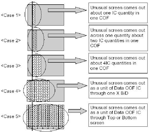
Generates Unusual Pattern of Data COF IC unit
(1) In case of generating unusual pattern of Data COF IC unit as below picture,
there is problem in the check that is input into Data COF IC
(2) In case of <case 1, 2, 3>
> confirm the connection of Data COF connector
> replace the relevant X B/D
(3) In case of <case 4, 5>
> confirm the connector that is connected from CTRL to X B/D
> Replace relevant XB/D or CTRL B/D
(2) In case of <case 1, 2, 3>
> confirm the connection of Data COF connector
> replace the relevant X B/D
(3) In case of <case 4, 5>
> confirm the connector that is connected from CTRL to X B/D
> Replace relevant XB/D or CTRL B/D
Screen Display Form
Regular Stripe is Generated about the Quantity of one Data COF IC
or more
(1) In case of generating regular stripe about the quantity of one Data COF IC, there is problem at the output of output flatworm of X B/D In case of generating regular stripe about the quantity of two Data COF IC, that means the data which is conveyed from CTRL B/D doesn’t conveyed well.
(2) Confirm the XB/D connection connector plugged in well.
Correspond to unusual screen.
(3) Replace relevant XB/D or CTRL B/D.
The screen display has a problem for Scan FFC.
(1) It’s may be a problem between Scan FFC and Y B/D.
(2) Check the connection of Y B/D and Scan COF.
(3) If the Scan IC is failed, replace the Y DRV B/D.
(1) It’s may be a problem between Scan FFC and Y B/D.
(2) Check the connection of Y B/D and Scan COF.
(3) If the Scan IC is failed, replace the Y DRV B/D.
Check a method of SCAN IC

The screen has a vertical line with regular gap. (A vertical
stripe flash at especial color)
(1) This is a problem about control B/D.
(2) Replace Control B/D.
(1) This is a problem about control B/D.
(2) Replace Control B/D.
A data copy is happened into vertical direction
(1) In this case, it’s due to incorrect marking of scan wave.
(2) Replace a Y DRV B/D or Y SUS B/D.
(1) In this case, it’s due to incorrect marking of scan wave.
(2) Replace a Y DRV B/D or Y SUS B/D.
The screen has one or several vertical line
(1) In this case, It isn’t a problem about controller B/D or X B/D.
(2) It may cause followings.
> It’s out of order a panel
> Open or short of DATA COF FPC attached panel
> It’s out of order a DATA COF attached panel
(3) Replace Module.
(1) In this case, It isn’t a problem about controller B/D or X B/D.
(2) It may cause followings.
> It’s out of order a panel
> Open or short of DATA COF FPC attached panel
> It’s out of order a DATA COF attached panel
(3) Replace Module.
The screen has one or several horizontal line
(1) In this case, it isn’t a problem about controller B/D or X B/D.
(2) It may cause followings.
> It’s out of order a panel
> Open or short of SCAN FPC attached panel
> It’s out of order a SCAN IC attached panel
(3) Replace Y DRV B/D
(1) In this case, it isn’t a problem about controller B/D or X B/D.
(2) It may cause followings.
> It’s out of order a panel
> Open or short of SCAN FPC attached panel
> It’s out of order a SCAN IC attached panel
(3) Replace Y DRV B/D
The screen displays input signal pattern but the brightness is
dark
(1) In this case, Z B/D operation isn’t complete.
(2) Check the power cord of Z B/D.
(3) Check the connector of Z B/D and Controller B/D.
(4) Replace the Controller B/D or Z B/D.
(1) In this case, Z B/D operation isn’t complete.
(2) Check the power cord of Z B/D.
(3) Check the connector of Z B/D and Controller B/D.
(4) Replace the Controller B/D or Z B/D.
The screen displays other color partially on full white screen or
happens discharge partially on full black screen.
(1) Check the declination of Y B/D set up set down wave.
(2) Check the declination of Z B/D ¢«ramp wave.
(3) Measure each output wave with oscilloscope (more than 200MHz) Adjust the Y B/D set up(Test-up:B/C[¥s/¥s])/setdown(Testdown: D[¥s]) and Z B/D ramp(Tramp:F/G[¥s/¥s]) declination by changing VR1/VR2/VR3.
> Measuring Point of Y B/D : P4 (Connector P4 36 pin)
> Measuring Point of Z B/D : B37 (SUS_OUT)
A center of screen is darker than
edge of screen at full white pattern.
(1) In this case, it’s a problem about Z B/D ramp wave.
(2) Check the connection cable of Z B/D and CTRL B/D.
(3) Replace the Z B/D.
(1) In this case, it’s a problem about Z B/D ramp wave.
(2) Check the connection cable of Z B/D and CTRL B/D.
(3) Replace the Z B/D.
It doesn’t display a specified brightness at specified color
(1) Check the connector of CTRL B/D input signal.
(2) Replace the CTRL B/D.
(1) Check the connector of CTRL B/D input signal.
(2) Replace the CTRL B/D.