Thursday, February 10, 2022

Sony CD-DVD RECEIVER HCD-SHAKE10-SHAKE30-HCDSHAKEX10-HCDSHAKEX30-HCDSHAKEX70 how to release disc tray lock, how to check the software version, destination display mode, error codes, panel board schematic


US model-Canadian model: HCD-SHAKE10,  HCD SHAKE30
AEP Model, Thai Model: HCDSHAKEX30, HCDSHAKEX70
UK Model: HCDSHAKEX30
Russian Model, Australian Model: HCDSHAKEX10, HCDSHAKEX30
E Model: HCDSHAKEX10, HCDSHAKEX30, HCDSHAKEX70

• HCD-SHAKE10 is the tuner, USB, CD Player, Bluetooth, NFC and amplifier section in SHAKE-X10.
• HCD-SHAKE30 is the tuner, USB, CD Player, Bluetooth, NFC and amplifier section in SHAKE-X30.
• HCDSHAKEX10 is the tuner, USB, DVD Player, Bluetooth, NFC and amplifier section in SHAKE-X10D.
• HCDSHAKEX30 is the tuner, USB, DVD Player, Bluetooth, NFC and amplifier section in SHAKE-X30D.
• HCDSHAKEX70 is the tuner, USB, DVD Player, Bluetooth, NFC and amplifier section in SHAKE-X70D

 [Be sure to keep your PC used for service and checking of this unit always updated with the latest version of your anti-virus software.  In case a virus affected unit was found during service, contact your Service Headquarters]

CD/DVD Mechanism Type :- CDM90-DVBU204 M.  Optical Pick-up Name :- CMS-S76RFS7GP OR CMS-S76RFS7G1

POWER OUTPUT AND TOTAL HARMONIC DISTORTION:
(US models only)
Shake-X30 only
With 4 ohm loads, both channels driven, from 150 Hz – 20,000 Hz; rated 90 watts per channel minimum RMS power, with no more than 0.7% total harmonic distortion from 250 milliwatts to rated output.
Shake-X10 only
With 4 ohm loads, both channels driven, from 150 Hz – 20,000 Hz; rated 80 watts per channel minimum RMS power, with no more than 0.7% total harmonic distortion from 250 milliwatts to rated output.

 NOTES ON CHIP COMPONENT REPLACEMENT

Never reuse a disconnected chip component.
Notice that the minus (--) side of a Tantalum capacitor may be damaged by heat.

LEAKAGE TEST
The AC leakage from any exposed metal part to earth ground and from all exposed metal parts to any exposed metal part having a return to chassis, must not exceed 0.5 mA (500 microamperes).
Leakage current can be measured by any one of three methods.
1. A commercial leakage tester, such as the Simpson 229 or RCA WT-540A. Follow the manufacturers’ instructions to use these instruments.
2. A battery-operated AC milliammeter. The Data Precision 245 digital multimeter is suitable for this job.
3. Measuring the voltage drop across a resistor by means of a VOM or battery-operated AC voltmeter. The “limit” indication is 0.75 V, so analog meters must have an accurate low-voltage scale. The Simpson 250 and Sanwa SH-63Trd are examples of a passive VOM that is suitable. Nearly all battery operated digital multimeters that have a 2V AC range are suitable.

The laser diode in the optical pick-up block may suffer electrostatic break-down because of the potential difference generated by the charged electrostatic load, etc. on clothing and the human body.
During repair, pay attention to electrostatic break-down and also use the procedure in the printed matter which is included in the repair parts.
The flexible board is easily damaged and should be handled with care.

NOTES ON LASER DIODE EMISSION CHECK
The laser beam on this model is concentrated so as to be focused on the disc reflective surface by the objective lens in the optical pickup block. Therefore, when checking the laser diode emission, observe from more than 30 cm away from the objective lens.

 How to release the disc tray lock

The disc tray lock function for the antitheft of sample disc in the shop is equipped.  It can release the lock function in the following procedure.

Releasing Procedure:
1. Press the POWER button to turn the power on.
2. Press the [FUNCTION] button to select the DVD/CD function.
3. Press the [ENTER] button and [VOCAL FADER] button simultaneously for three seconds.
4. The message “UNLOCKED” is displayed on the screen display panel and the disc tray is unlocked.
Note: When “LOCKED” is displayed on the screen display panel, the disc tray lock is not released by turning the power ,ON-OFF with the POWER button.

Connecting with a smartphone by one touch (NFC)

Note: The operation in this mode must use a NFC-compatible smartphone (Smartphones with a built-in NFC function [OS: Android 2.3.3 or later, excluding Android 3.x]
1. Press the [POWER] button to turn the power on.
2. Download and install the app “NFC Easy Connect”.
Download the free Android app from Google Play by searching for “NFC Easy Connect”.
3. Start the app “NFC Easy Connect” on the smartphone.  Make sure that the application screen is displayed.
4. Touch the smartphone to the N-Mark on the system until the smartphone vibrates.  Complete the connection by following the instructions displayed on the smartphone.
5. When pairing is completed and the Bluetooth connection is established, the Bluetooth device name appears in the display panel.

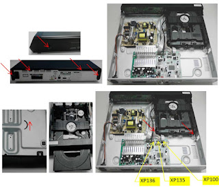
HOW TO OPEN THE TRAY WHEN POWER SWITCH TURN OFF
Note 1:
After the side (L, R) panel, top panel section, fan bracket and DC fan are removed, this work is done.
Note 2: Please prepare the thin wire (clip etc. processed to the length of 8 cm or more).

COLD RESET
This mode is used to reset all the user settings to factory setting.
Execute this mode when returning the unit to the customer.
Procedure:
1. Press POWER button to turn on the system.
2. Press STOP button and [ TUNING +>>|] button simultaneously for 3 seconds.
3. “COLD RESET” appears on the screen display panel. After that, “SONY DEMO” appears on the screen display panel.
The system automatically turn ON and OFF  once. Please be sure that the system stay at demo mode finally before switch off the power supply.

DISC TRAY LOCK
When the disc tray does not open and “LOCKED” appears on the screen display panel, disc tray lock mode has been activated by the shop front.
To release from Disc Tray Lock Mode
1. Press POWER button to turn on the system.
2. Press [FUNCTION] button repeatedly to select DVD/CD function.
3. Press [ENTER] button and [VOCAL FADER] button simultaneously and hold down until “UNLOCKED” displayed on the screen display panel.

PANEL TEST MODE
This mode is used to check the buttons, knobs, screen display panel and LEDs.
Procedure:
1. Press [POWER] to turn on the system.
2. Press STOP button and [ TUNING – ] button simultaneously for 3 seconds.
3. All LEDs and segments in screen display panel are lighted up.
This is the display check mode.
Press [ENTER] button repeatedly to toggle different display mode as below.
Segments on screen display panel:
All On --> 1st Group On --> 2nd Group On --> All On --> All Off
Single color LEDs:
All On --> 1st Group On --> 2nd Group On --> All On --> All Off
Multi Color LEDs: White --> Red --> Green --> Blue --> Off
4. Press [ S1 ] button, the button and knob check mode is activated.
5. In the button and knob check mode, the screen display panel displays “K 0 E0V0”.
Each time a button is pressed, “K” value increases.  However, once a button has been pressed, it is no longer taken into account. After all the buttons have been pressed, "K" value will toggle between "OK" and "K26".
“E” value increases in the manner of 0, 1, 2, 3 ... if [MIC/GUITAR LEVEL] knob is turned clockwise, or it decreases in the manner of 0, 9, 8, 7 ... if [MIC/GUITAR LEVEL] knob is turned counterclockwise.
“V” value increases in the manner of 0, 1, 2, 3 ... if [VOLUME/DJ CONTROL] knob is turned clockwise, or it decreases in the manner of 0, 9, 8, 7 ... if [VOLUME/ DJ CONTROL] knob is turned counterclockwise.
6. To release from this mode, press the buttons in the same manner as step 2, or disconnect the power cord.

VERSION DISPLAY MODE
This mode is used to check the software version.
Procedure:
1. Press POWER button to turn on the system.
2. Press [ S3TUNING – |<<] button and [LIGHT MODE] button simultaneously for 3 seconds.
The SC software version and CD/DVD software appear on the screen display panel.
After that, it returns to the default display.

MODEL AND DESTINATION DISPLAY MODE
This mode is used to check the model and destination of the set.
Procedure:
1. Press POWER button to turn on the system.
2. Press STOP] button and [S3 TUNING – |<<.] button simultaneously for 3 seconds.  All segments in screen display panel are lighted up.
3. Press [ S2 + ] button. Model information appears on the screen display panel.
4. Press [ S2 + ] button again. Destination information appears on the screen display panel.
5. Press S2  button and [ TUNING – |<< ] button simultaneously for 3 seconds to exit.

SHOP FRONT DEMO
The playback started automatically and the “ * DEMO * ” appears on the screen display panel.  This is the Shop Front Demo mode which is activated by the shop front.
To release from Shop Front Demo Mode
1. Press STOP button and [SOUND FIELD] button simultaneously for 5 seconds.

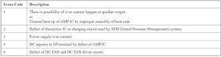
ERROR CODES
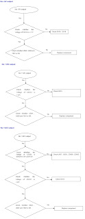
Switching Regulator [SMPS] (SSN-172AD) DIAGNOSIS FLOW (HCD-SHAKE10 – SHAKE30)

SWITCHING REGULATOR [SMPS] SSN-171AD DIAGNOSIS HCDSHAKEEX70

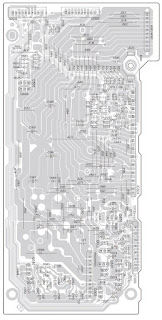
Top panel board schematic


Tuesday, January 25, 2022

Sony HT ST9 Sound bar – Sony SA ST9 Active speaker system How to enter the BD service mode, power board and amplifier board schematic


After correcting the original service problem, perform the following safety check before releasing the set to the customer: Check the antenna terminals, metal trim, “metallized” knobs, screws, and all other exposed metal parts for AC leakage.

All of the units included in the HT-ST9 (SAST9 - SA-WST9-Remote control) are required to confirming operation of SA-ST9. Check in advance that you have all of the units.

Be sure to keep your PC used for service and checking of this unit always updated with the latest version of your anti-virus software.
In case a virus affected unit was found during service, contact your Service Headquarters

NETWORK INFORMATION WRITING AND CHECKING OF NETWORK-NFC OPERATION
When the complete MB1406 board or card WLAN-BT combo are replaced, execute the below BD service mode. And check the operation of wireless or wired LAN and NFC.

Network information writing Procedure:
1. Connect this unit with TV monitor.
2. Press the POWER button to turn the power on.
3. Press button in order of the STOP → [DISPLAY] → PAUSE → [UP] on the remote commander.
(Make the interval when each button is pressed within one second)
4. Enter the BD service mode. The OSD menu on TV monitor can be operated by remote commander.
5. Press the DOWN button on the remote commander to select “Diag”, and press the [+] button on the remote commander.
6. Press the RIGHT button on the remote commander to select “Wireless LAN Test”. (Screen 1)
7. Press the DOWN button on the remote commander to select “[5] Write P2P address to Registry”.
8. Press the [+] button on the remote commander, wait until the display show “Status: Write Successful!” (Screen 2).
9. Press the [BACK] button on the remote commander to return
to category select screen, and press the RIGHT button on the remote commander to select “Bluetooth Device Test”. (Screen 3)
10. Press the [+] button on the remote commander to select “(1) Bluetooth Enable”

11. Press the [+] button on the remote commander, wait until the display show “Status: Bluetooth Enable Successful!” (Screen 4).
12. Press the DOWN button on the remote commander to select “(3) Write Bluetooth device address to Registry”.
13. Press the [+] button on the remote commander, wait until the display show “Status: Write Successful!” (Screen 5).
14. Press the POWER button to turn the power off.

How to enter the BD service mode

BD SERVICE MODE
Note:
The operation in this mode must use a remote commander and TV monitor.
Setting method of the BD service mode:
1. Connect this unit with TV monitor.
2. Press the POWER button to turn the power on.
3. Press button in order of the STOP → [DISPLAY] → PAUSE → [UP] on the remote commander.
(Make the interval when each button is pressed within one second)
4. Enter the BD service mode. The OSD menu on TV monitor can be operated by remote commander.

WIRELESS SOUND COLD RESET
It can initialize various backup information of Subwoofer (SAWST9).
Preparation:
Connect the Subwoofer (SA-WST9) and the Bar Speaker (SAST9) by wireless.
Procedure:
1. Press the POWER button to turn the power on.
2. Press the buttons on the remote commander in the order of STOP → [DISPLAY] → [BACK] → [UP].
3. The on/standby indicator on the Subwoofer (SA-WST9) turns red and flashes, then turns on orange.

4. Unplug the AC cord on the Subwoofer (SA-WST9) from an outlet and insert the AC cord again.

Power board schematic and PWB

Amplifier board schematic


Friday, January 14, 2022

Panasonic SA DK10 DVD Stereo System - US and Canada model – (STK470-050A, RSN311W64B-P) - Power and Amp schematic, How to override the protection


Before Repair and Adjustment:
Disconnect AC power, discharge Power Supply Capacitors C566~C569, C782 and C591 through a 10Ω, 5W resistor to ground.
DO NOT SHORT-CIRCUIT DIRECTLY (with a screwdriver blade, for instance), as this may destroy solid state devices.
After repairs are completed, restore power gradually using a variac, to avoid over current.  Current consumption at AC 120V, 60 Hz in NO SIGNAL mode should be ~650mA.

Protection Circuitry
The protection circuitry may have operated if either of the following conditions are noticed:
• No sound is heard when the power is turned on.
• Sound stops during a performance.
The function of this circuitry is to prevent circuitry damage if, for example, the positive and negative speaker connection wires are “shorted”, or if speaker systems with an impedance less than the indicated rated impedance of the amplifier are used.
If this occurs, follow the procedure outlines below:
1. Turn off the power.
2. Determine the cause of the problem and correct it.
3. Turn on the power once again after one minute.
Note : When the protection circuitry functions, the unit will not operate unless the power is first turned OFF and then ON again.

Power supply: AC 120 V, 60Hz

Area: U.S.A - Canada, Signal system: NTSC

TAPE SECTION : AR2 MECHANISM SERIES

CD SECTION : RAE0152Z-3 TRAVERSE DECK SERIES

1.The traverse deck (optical pickup) is an extremely high precision construction and should not be subjected to impact, excessive vibration, or other types of rough handling.
2. In order to prevent static electricity damage to the laser diode, use a short pin or similar tool to short the optical pickup’s flexible circuit boards after they have been disconnected from the main circuit board.
3. Handle the flexible circuit boards with care; excessive force could cause them to be broken.
4. Do not turn the pre-set variable resistor (for adjustment of the laser power); it has been adjusted at the factory.

Beam source: Semiconductor Laser

Total stereo mode power: 65 W per channel (8 Ω)

Record - playback head: Solid permalloy head

Erasure head: Double gap ferrite head

Disc: DVD-Video

Gear for servicing (jig) information

Head Azimuth adjustment

1. Connect the measuring instrument.
2. Replace azimuth screws for both forward and reverse direction after removing the screw-locking bond left on the head base.
3. Playback the azimuth adjustment portion (8kHz, -20dB) of test tape (QZZCFM). Adjust the azimuth adjusting screw until the outputs of the L/Rch are maximized.
Make sure that the difference in the peak level between the left and right channels does not exceed 5dB.
4. Perform the same adjustment in reverse playback mode.
Check of the level difference forward and reverse directions
5. Playback the playback gain adjustment portion (315Hz, 0dB) of test tape (QZZCFM). Check if level difference between forward and reverse direction is within 1.5dB.
6. After the adjustment, apply screw lock to the azimuth adjusting screw.

Transistors and Diodes

Power Amp and Power schematic

Transformer circuit diagram

Printed circuit board – Power Amp

Repairing the mechanism is an expertise work.  Please do not try to do it yourself at home.


Tuesday, January 04, 2022

Philips Home Theatre DVD Player HTD5570 – Disassemble, SMPS and amplifier circuit diagram, troubleshooting, software upgrade procedure, connector pin voltage details.


Safety regulations require that during a repair:
Connect the unit to the mains via an isolation transformer.
Replace safety components indicated by the symbol , only by components identical to the original ones. Any other component substitution (other than original type) may increase risk of fire or electrical shock hazard.

Be careful during measurements in the live voltage section. The primary side of the power supply , including the heat sink, carries live mains voltage when you connect the player to the mains (even when the player is “off”!). It is possible to touch copper tracks and/or components in this unshielded primary area, when you service the player. Service personnel must take precautions to prevent touching this area or components in this area.

A “lighting stroke” and a stripe-marked printing on the printed wiring board, indicate the primary side of the power supply.

This unit employs a laser. Only qualified service personnel may remove the cover, or attempt to service this device (due to possible eye injury).

Note: Never replace modules, or components, while the unit is “on”

Centre speaker:

Output power: 166 W RMS (30% THD)

Speaker impedance: 4 ohm
Speaker drivers: 1 x 78 mm (3") full range
Dimensions (WxHxD): 223 x 100 x 80 mm
 Weight: 0.65 kg

Front/Rear speaker:
Output power: 4 x 166 W RMS (30% THD)
Speaker impedance: 4 ohm
Speaker drivers: 1 x 78 mm (3") full range
Dimensions (WxHxD):
HTD5510: 90 x 185 x 82 mm (front/ rear)

Subwoofer
Output power: 166 W RMS (30% THD)
Impedance: 4 ohm
Speaker drivers: 165 mm (6.5") woofer
Dimensions (WxHxD): 178 x 300 x 343 mm
Weight: 3.66 kg
Cable length: 3.3 m

Procedure of replacing the defective loader.

Solder the ESD protection point.

Put a paper clip on the flex foil to short circuit the contacts [see the fig]

Replace the defective loader with new loader

Remove paper clip from the flex foil and connect it to the new loader

Remove solder joint on ESD protection point

[The laser diode of this loader is protected against ESD by a solder  a point short-circuits the laser diode to ground.  For proper functionality of the loader this solder joint must be removed after connecting loader to the set.

Dismantling

Open the top cover. Remove 2 screws on both sides and 4 screws on back panel, then open the cover.

Dismantle the loader. Open the tray, dismantle the CD door, remove 2 screws beside the loader. disconnect connectors(XP100,XP135,XP136),then pull up the loader.

Dismantle the main board. Disconnect connectors(XP221,XP82,XS751),remove 2 screws on the board and 6 screws on back panel.

Dismantle the power board. Remove 4 screws on the board.


Dismantle the front panel and the front control board. Loosen the 2 buckles on both sides and 2 buckles under bottom cover, then remove 5 screws on the front control board.

Software Upgrade

There are 2 ways to software upgrade:
First:
Upgrade from USB:
Copy the upgrade file HTD5510_X X.BIN to USB then press the USB key on RC or SOURCE key on front panel.
When upgrade file detected, select "Yes" to upgrade, select "Cancel" to cancel.
After upgrading begins, a message “DO NOT POWER OFF” will show, or the product will hang up and upgrading failed.

Second:
Upgrade from Disc:
Copy the upgrade file HTD5510_X X.BIN to disc then read the disc.
When upgrade file detected, select "Yes" to upgrade, select “Cancel “to cancel.
After upgrading begins, a message “DO NOT POWER OFF” will show, or the product will hang up and upgrading failed.
2. Check the version information after upgraded.
Press the setup key on RC , select Preference Setup, and then Version info , press OK Key you will see a interface below:

Troubleshooting chart


Power board schematic


Amplifier board circuit diagram TAS 5342 and TAS 5252

CONNECTOR PIN VOLTAGES


Monday, December 20, 2021

Panasonic TH49EX430M LED TV – how to enter the factory mode, adjustment procedures, audio amplifier schematic and more


Always respect voltages. It makes sense to avoid exposure to electrical shock.  While some sources are expected to have a possible dangerous impact, others of quite high potential are of limited current and are sometimes held in less regard.

These chassis are designed for Latin America (LA) markets ready for IPTV. The main chip is from Mstar and supports below features matrix.

All tests and measurements mentioned hereafter have to be carried out at a normal mains voltage (100 ~ 240 VAC)
All voltages have to be measured with respect to ground, unless otherwise stated
All final tests have to be done on a complete set including LCD panel in a room with temperature of 25+or-7°C

The Picture Performance assessment such as White Balance (luminance and colour temperature) has to be performed into subdued lighted room after at least 45min of warm-up in order to avoid any temperature drift influence (colorimetry vs time)

Pre-Conditions and DC/DC Check
Before power-on, please check the board according to the relevant block diagram and circuit diagram, and make sure that no serious issue or mistake can destroy the board. 

For example, the output of DC/DC and LDO should not be shorted to ground.
Supply a suited voltage and power-on, then check the voltage according to the relevant block diagram, circuit diagram and voltage spec. The error should less than 5%. 

For example, the voltage for main chip (+3V3, AV3.3, +1V2, CORE1V, etc.), the voltage for DDR (DDRV), the voltage for amplifier (AMP-VCC), etc...

Project ID Modification
There are different ID stored into the NVM depending on different Panels settings and Models features, but there’s only one key branching Project ID that includes all. So, it’s not recommended to modify Panel ID with Hyper terminal as other ID features may not change.
To modify Project ID, you need to go through “Design menu Service menu Project ID”, then spin left or right with RCU “Zoom±” keys to suitable ID (Project name is dynamically refreshed).
 “How to change Project ID with RCU”

Process following subsequence IR codes to change project ID: 062598+MENU+xxx (xxx:Project ID, ex: 003) with TV automatic restart”

Once the boards (chassis, KB, IR, PSU…) and the panel are well interconnected, plug all external generator devices to relevant inputs-outputs below according to their respective test patterns format and check picture content and sound quality accordingly:

Audio tones can be defined by the factory (i.e. 1 KHz & 3 KHz sweep).
Picture video formats can be changed by the factory according to their own standard.

AD Calibration Test

As SoC is built-in an A-D self-calibration mechanism, ADC need not to be performed any more.

DDC & EDID & T-Link Test

The E-EDID data structures are according to VESA Enhanced EDID 1.3 (and EIA-CEA-861B for HDMI). CEA Timing Extension structure has been extended to support all 3D capable timings.
All VGA and HDMI structures have their own BIN profile which are part of main SW and uploaded at power-on into HDMI switch chipset.
For EDID check, it’s needed to check whether the correct EDID is downloaded by checking corresponding EDID NVM Checksum or read them out to check bit by bit if it is in line with the released EDID bin file.

HDCP Test

For HDCP compliancy, it’s needed to check whether the HDCP key has been well set.

Factory Menu 0r (The service mode menu)

Follow the below steps to pop-up the Factory menu in case of “Factory Key” is disabled:
- Press RCU “MENU” key to display main menu
- Select “Setting” and press “OK” key to enter into setting submenu
- Select “Picture” and press “OK” key to enter into picture submenu
- Scroll down to “Contrast” item
- Press the subsequence RCU keys “
9”, “7”, “3” and “5
In case of “Factory Key” is enabled, just press RCU “Return” key to pop-up again the Factory menu.
The status of “Factory Key” can be changed in Factory Menu->Hotkey.
Press RCU “OK” key or “RIGHT” key to enter the submenu.
Press RCU “Menu” key to go back to the root menu.
Press RCU “RIGHT” or “LEFT” key to change the values.
Press RCU “OK” key run the function.
Press RCU “Exit” key exit the Factory menu.

Factory Menu Description

Warm-up

Following TCL standard and practices, it’s required minimum 15min of Warm-Up that can be considered as Burn-In.
Additional Aging for White Balance alignment is no more necessary due to consistent Picture Performance with Cloning usage.
This function is accessible by selecting “Factory menu WARM-UP”, pressing RCU “Zoom+” key and then leaving Factory menu. Other faster methods are available on above enclosed SIACP requirements.

SHOP-END initial

At final process stage, it’s necessary to perform “Reset shop” before any packing to leave
Factory mode and restore User default presets.  This function is accessible by selecting “Factory menu SHOP init”, then pressing RCU “OK” key. Other faster methods are available on above enclosed SIACP requirements

“How to upgrade FLASH SW using USB”

Copy the SW BIN image “V8-S68AT03-LF1VXXX.bin” into USB stick root path.
 “How to upgrade FLASH SW using USB”
Note: If there’s already other “V8-S68AT03-LF1VXXX.bin” into USB root, it needs to be deleted or renamed

Plug USB stick to the TV USB slot.
Press RCU MENUSetting Software upgradeBy USBConfirm.
Or, turn off the TV press and hold the power key of key board before reconnect AC cord to restart TV for 5-8seconds (Forced Upgrade).
When the "UPGRADING SOFTWARE" picture appears, it means TV is uploading SW BIN image. Waiting a few minutes.

When updating is successful, TV should restart automatically.

“How to upgrade MAC Address

Upgrading MAC address need to use the tool in factory and through serial command, the specific methods according to the operation of the factory guidance.

Factory hotkey submenu and Warm-Up Mode submenu

White Balance submenu, Shop init submenu, NVM Reset submenu

Power On Mode submenu, USB UPDATE submenu, Device ID test submenu

“Instructions of Updating SW”

Audio amplifier schematic


Sunday, December 05, 2021

Haier 40DR3505 – How to enter the service mode, How to upgrade the software, Panel failure symptoms – MSD3393LU Chassis


How to enter into Service Mode
The way to the factory mode menu:
Step 1: Press Menu,
Step 2: Press “8893”,
System will be into the factory mode menu when 2 steps above are done.
At the end of the main factory menu, you can see the edition of the software, like this" BUILD TIME 2014-01-21 23:17:21
VERSION v1.0 ”.

How to exit
If you want to exit this factory menu, please press the button ”Exit” on the remote.
System will be out the factory mode menu.

In factory mode menu, press up/down button to choose the up/down item, press right or OK button to the submenu. Press MENU button to go back.

GENERAL SETTING
1) Init Flash;
2) Uart Enable:Choose on or off in Uart Enable;
3) Dbg Message Enable: Choose on or off in Dbg Message Enable;
4) Test Pattern: Choose the Pattern picture;
5) Dynamic Contrast: Choose on or off in Dynamic Contrast;
6) Power On Mode:Choose on or off in Power On Mode;
7) Mirror Control: Choose on or off in Mirror Control;
8) Front End Status
9) Timer Test
10) SSC
11) Erase Flash
12) PQ Advance Debug: Choose on or off in PQ  Advance Debug;
13) Factory remote: Open or close the Factory remote;
14) Factory CH Export.


Adjust the Picture Mode, Picture Curve, White Balance and Over Scan in different source.

SOUND
Adjust the values of Sound Mode, Volume Curve, Audio Output and True Volume in different source.


Panel Setting
1) LVDS Bit Mode: choose the Bit;
2) LVDS MAP: choose the MAP;
3) LVDS ODD/Even: choose ODD or Even;
4) Backlight: Adjust the value of backlight;
5) Reset Panel Setting Date
6) 6MX0 LVDS Map: choose the 6MX0 LVDS MAP;
7)  6MX0 Channel: choose the 6MX0 Channel;
8) 6MX0 Mirror: choose the 6MX0 Mirror;
9) 6MX0 Demo: choose the 6MX0 Demo;
10) 6MX0 Update.


Software update

MSD3393LU software update
1. Copy the software files to a USB disk on the root directory;

2. Insert the USB disk when the AC power is off;
3. Turn on the AC power in turn to begin;
4. Turn off the AC power until the indicator light fast twinkling;
5. Pull out the USB disk and power on the television.
Note:
Do not turn off the TV while it is updating.


1.Mainchip—MSD3393LU(U1)
2. Audio Amplifier—TPA3110D2PWPR (UA1)
3.Main Flash Memory—GD25Q32BSIG (UF1)
4.DC/DC convertor 5V-1.8V for MSD3393LU (U1)—LC1117CLTRAD (UL2)
5.voltage convertor 5V to 3.3V_STB —LC1117CLTR33 (UL1)
6.voltage convertor 5V to 1.15V_STB —LC3406CB5TR (UD1)
7.voltage convertor 5V to 3V for tuner—LC1117CLTR33 (UT1)
8.Tuner —SDCL1005CR33JTDF (RFT1)

Panel failure symptoms